FAB ACADEMY 2016
FINAL PROJECT: 'ITEM WATCHMAN'
0. Requirement for final project
below is the requirement for Final Project.
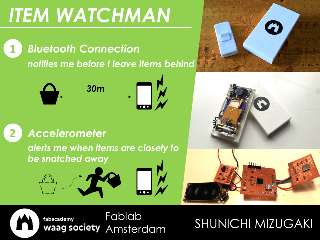
1. Project Summary: 'ITEM WATCHMAN'
Background and summary
Since I did so many lost property, I would like to make lost property prevention attachment, which can let us know by beeping if we leave the property without taking as below.
Main functions are:
- Bluetooth connection notifies me before I leave items behind over 30m or so.
- Accelerometer alerts me when items are closely to be snatched away by thief.
Final Presentation
Below are the presentation slide and video of my final project.
PRESENTATION SLIDE
PRESENTATION VIDEO
Design files
Here is the design files that I made for this final project:
(electrical part)
-
Main microcontroller module: Fabkit(EAGLE):
schematic.SRC / board.BRD / trace.PNG / cutting.PNG holes.PNG - Input module: accelerometer board(EAGLE):
schematic.SRC / board.BRD / trace.PNG / cutting.PNG - Output module: speaker board(EAGLE):
schematic.SRC / board.BRD / trace.PNG / cutting.PNG
(mechanical(design) part)
- Plastic Case of the device(Fusion 360): Top.STL / Bottom.STL
- Decoration sticker(Inkscape): sticker.PDF
(programming part)
- software/arduino code: watchman.INO
Bill of material(BOM)
Below is the BOM (bill of material) of my final project. It cost 56.5USD totally.
Bill of Material(BOM)
Overview of Component and Development Process
(electrical part)
- Main microcontroller module (equivalent to Arduino: Fabkit)
- Make Fabkit board
- Input module: accelerometer board
- Design the schematic and board (EAGLE)
- Mill the board by CNC milling machine (Modella)
- Solder the components
- Embed programming and check function (Arduino)
- Output module: speaker board
- Design the schematic and board (EAGLE)
- Mill the board by CNC milling machine (Modella)
- Solder the components
- Embed programming and check function (Arduino)
- Network module: Bluetooth Law Energy Module
- Battery module
- Calculate appropriate power supply
- Check workability
- Integrate functions above into one device
(mechanical(design) part)
- Plastic Case of the device
- Design the plastic frame/case (Fusion360)
- 3D print it (3D Printer)
- Decoration sticker
- Design sticker (Inkscape)
- Cut sticker by vinyl cutter
(programming part)
- software/arduino code
- Write the code for each board
- Integrate the function of all boards
2-1. Project Development Process - electrical&programming part
First, I made each functional boards(maim board, input module and output module), and after that, I integrate them into one device.
1) Main microcontroller module (equivalent to Arduino: Fabkit)
I made Fabkit as a main microcontroller module for my project, so you can check the process on Week11: Input Device page.
2) Input module: accelerometer board
Also, I made accelerometer board as a Input Module for my project, so you can check the process on Week11: Input Device page.
3) Output module: speaker board
Next, I made speaker board as a Output Module for my project, so you can check the process on Week13: Output Device page.
4) Network module: Bluetooth Law Energy Module
Actually, I was not able to complete this part because of lack of my time, skills and other factors...however, you can see the process and progress on Week15: Networking and Communications.
5) Integrate functions above into one device
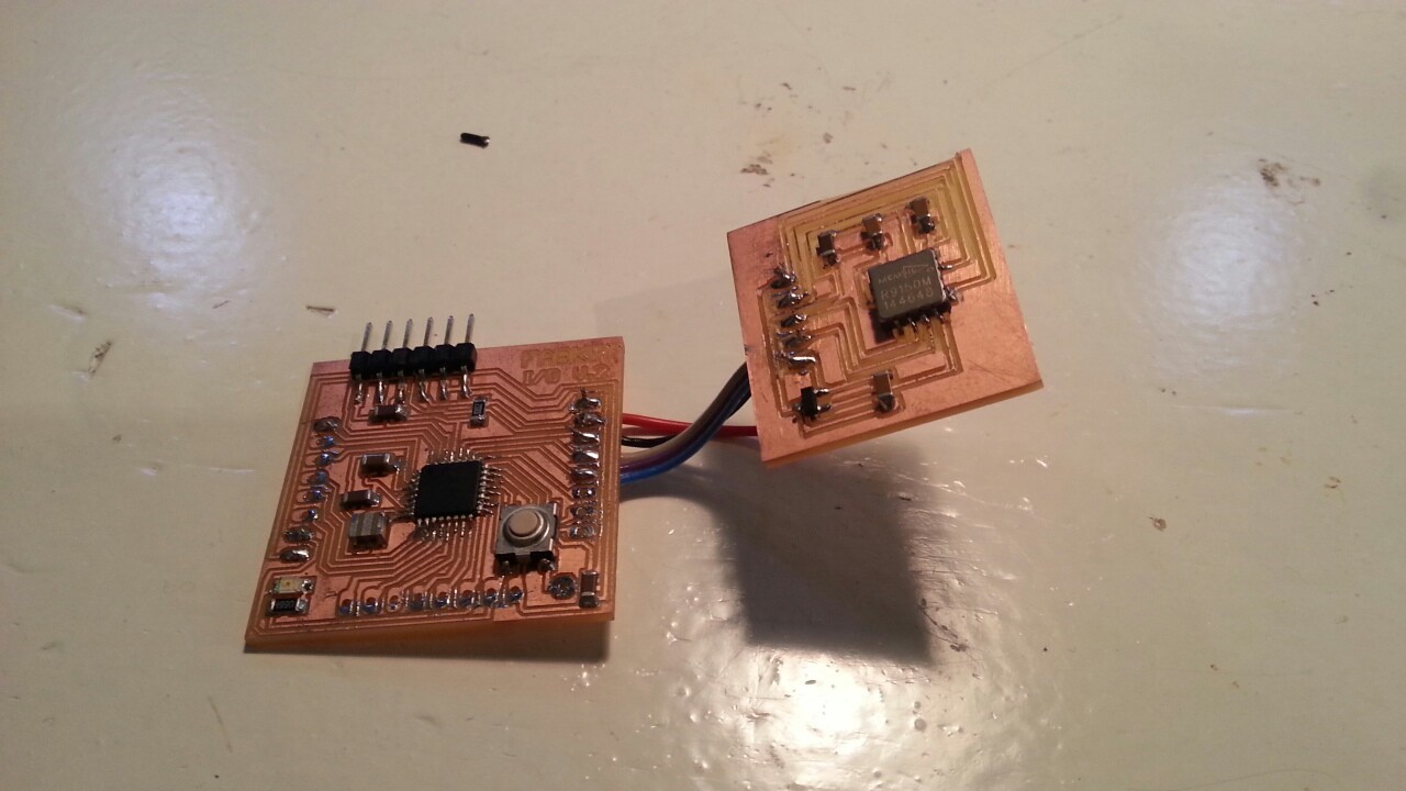
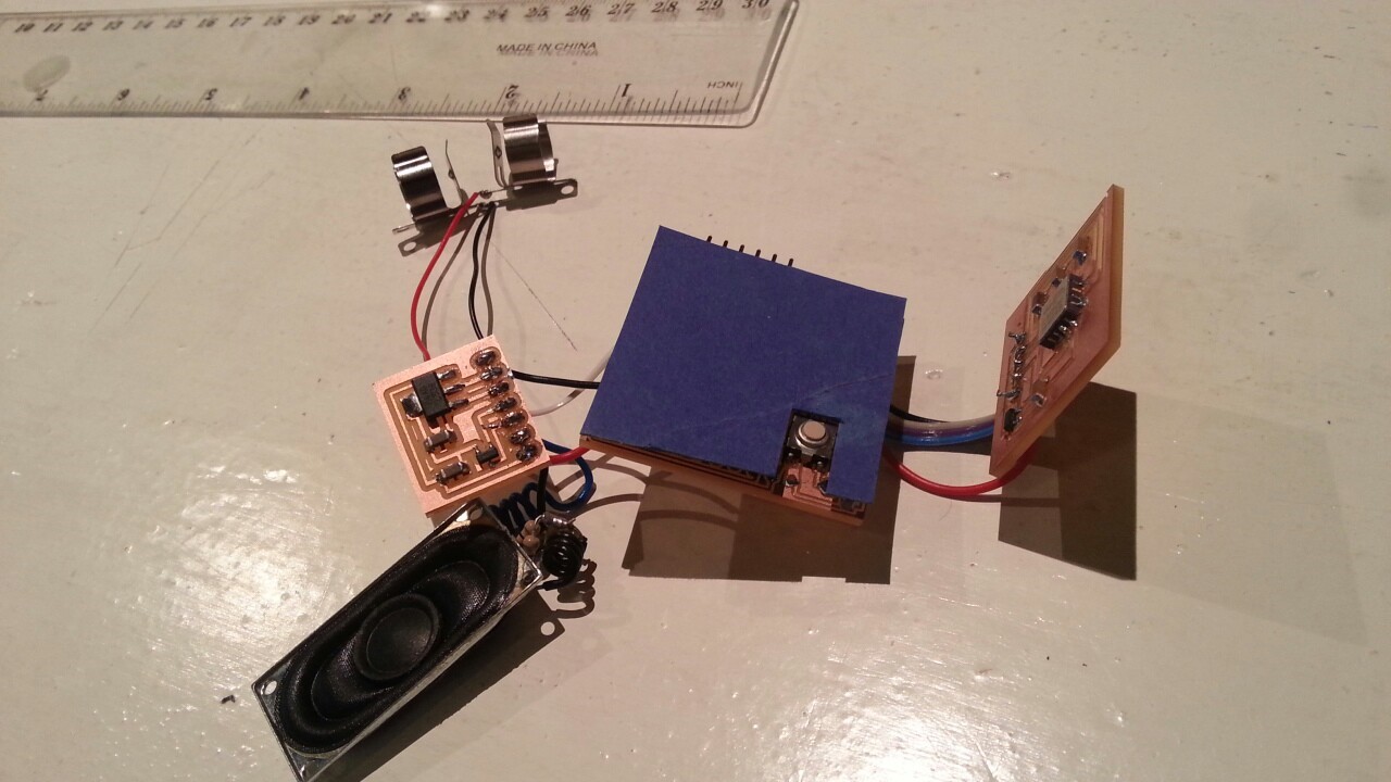
After making the boards, I had to integrate them so that they could work as one device. I connected two boards and speaker module to Fabkit and solderred them with wire tentatively as below. During these trial, I used external power suppy.
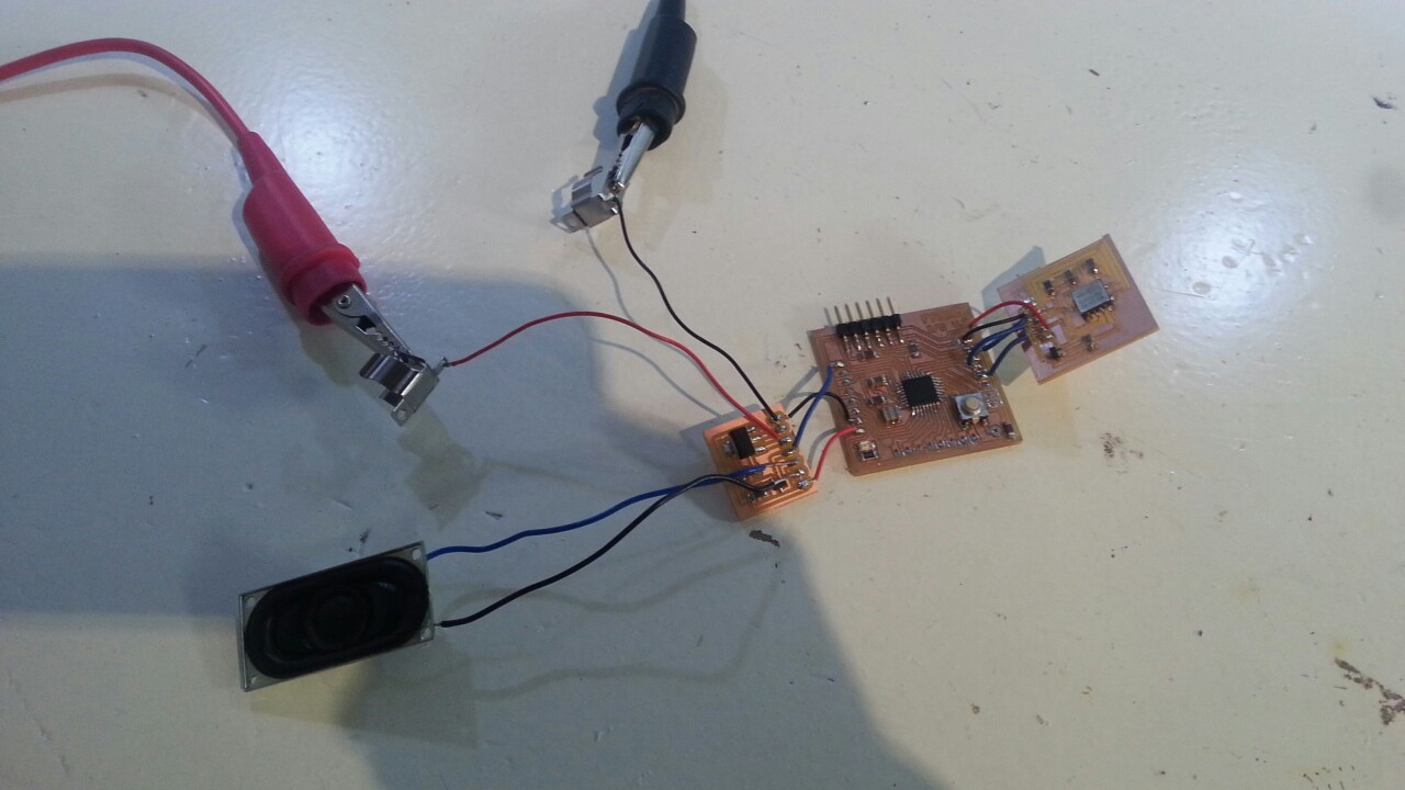
Connected boards
Then, I wrote the integrated code with two boards' function, which can;
- First, accelerometer can detect the motion/acceleration
- Second, the microcontroller judge if the value from accelerometer exceed the value of thresold or NOT
- If exceeded, the speaker give sounds.
Speaker code with threshold on accelerometer
#define BEAT 300 // define the length of the sound #define PINNO 2 // Pin number #includeint pin_x = 17; int pin_y = 18; int pin_z = 19; byte val_x = 0; byte val_y = 0; byte val_z = 0; int threshold = 150 // if the parameter over threshold, speaker sounds void setup() { Serial.begin(9600); pinMode(pin_x, INPUT); pinMode(pin_y, INPUT); pinMode(pin_z, INPUT); } void loop() { val_x = analogRead(pin_x); val_y = analogRead(pin_y); val_z = analogRead(pin_z); Serial.print(val_x); Serial.print(", "); Serial.print(val_y); Serial.print(", "); Serial.print(val_z); Serial.print(", "); Serial.println(""); delay(10); if ( val_x > threshold || val_y > threshold || val_z > threshold) { tone(PINNO,262,BEAT) ; // C delay(BEAT) ; tone(PINNO,294,BEAT) ; // D delay(BEAT) ; tone(PINNO,330,BEAT) ; // E delay(BEAT) ; tone(PINNO,349,BEAT) ; // F delay(BEAT) ; tone(PINNO,392,BEAT) ; // G delay(BEAT) ; tone(PINNO,440,BEAT) ; // A delay(BEAT) ; tone(PINNO,494,BEAT) ; // B delay(BEAT) ; tone(PINNO,523,BEAT) ; // C delay(3000); } }
And after the several trial and error, I was able to get satisfying result as the presentation video shows.
6) Battery module
As a final image, I would like to make my project as a portable device, so I had to stop using the external power supply and find another way. I came up with the idea using small battery which I could put into even small device plastic case.
Any way, I had to find how much power supply was neccesary for the device to work. With a lor of help of Emma, we calculate the neccesary value of voltage and current for my device. From the result of calculation and several trials, I found that over 9V battery could work for my device.
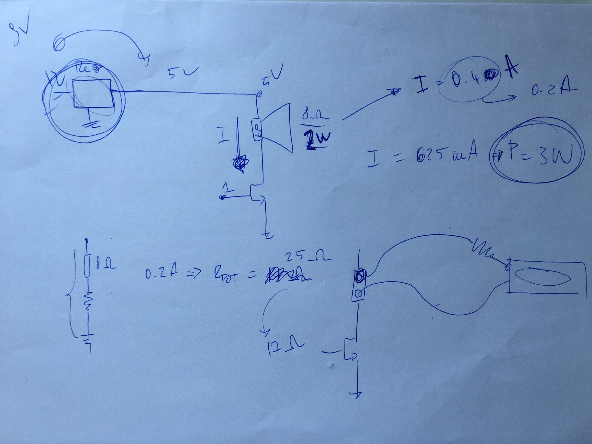
Calculation for neccesary power supply
Then, I looked for appropriate battery which could meet my requirement; small and over 9 voltage. After going around several shops in Amsterdam, I found the battery below, which seemed good.

small battery with 12V
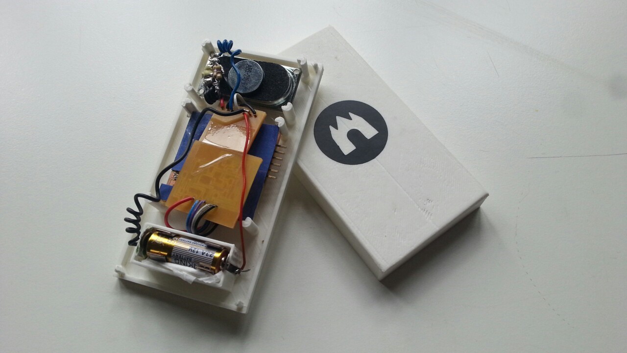
I attached the battery connector/jumper to my boards, and put the small battery on it. As a result, it worked well and I was so satisfied with it.
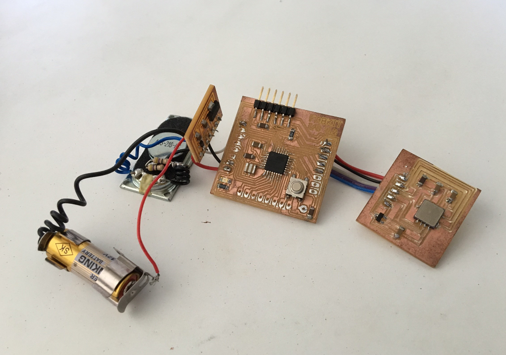
Integrated electrical parts
2-2. Project Development Process - mechanical and assembling part
Finishing the electrical and programming part, I had to make outside design/frames and needed to assemble them in the end.
1) Plastic Case of the device
I decided to make the case/frame of the device by 3D printing because the approach was faster and more precisely compared to other ways: molding and casting, composite or so. Especially, my project was very small and needed to be precice modelling, so I chose 3D printing.
To design the case, I had to decide the size of it. I measured the scale of the electrical components and made the rough sketch of the case by hand. Though I wanted to make it as small as I could put it into my wallet or pocket, the size become 10cm * 5cm * 1cm because of the size of main board and speaker. They were quite big.
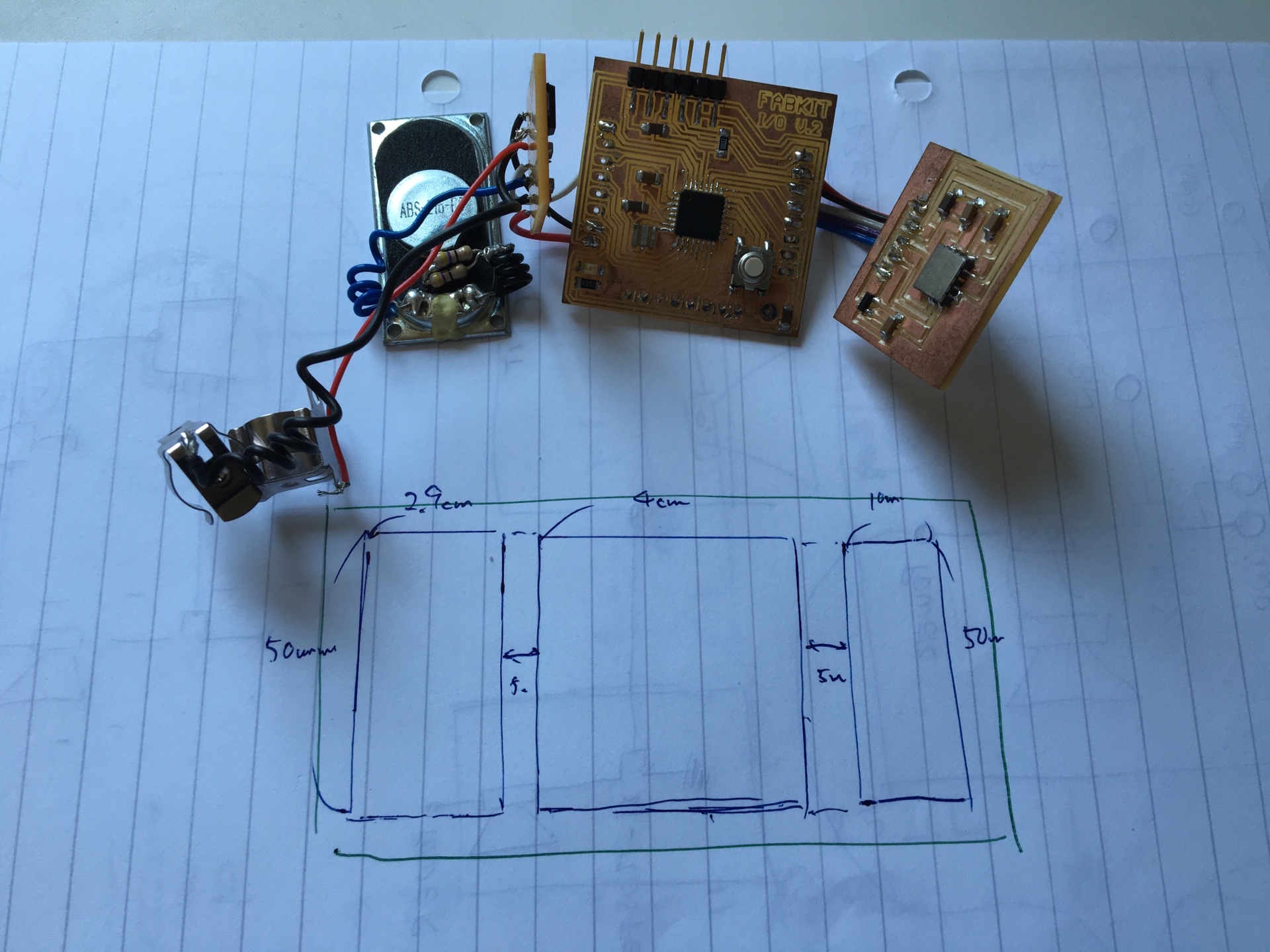
Hand skectch of the case
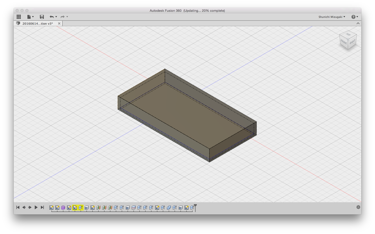
Using Fusion360, I made the precise 2D sketch of the case and then made the 3D blueprint as below. I added battery holder parts and stopper between top part and bottom part for the functionability of the case.

2D sketch on Fusion 360

3D design of the bottom part on Fusion 360
Top part
After prepation, I started to print, which was fairly straightforward and took only 2-3 hours. After printing, I added several holes to the flat part of top and bottom part, so that the speaker sounds could be delivered outside the case directly and loudly.

3D printerd plastic case
2) Decoration sticker
Though finishing printing, I felt it unfashionable because the case had no design. I decided to make it as custom-decorative device, and make the sticker by vinyl cutter.

The logo design of Fablab Amsterdam, operated by waag society
on Inkscape
I design the sticker on Inkscape and cut it by vinly cutter, and pasted it as below. It became quite better design, I think :-)
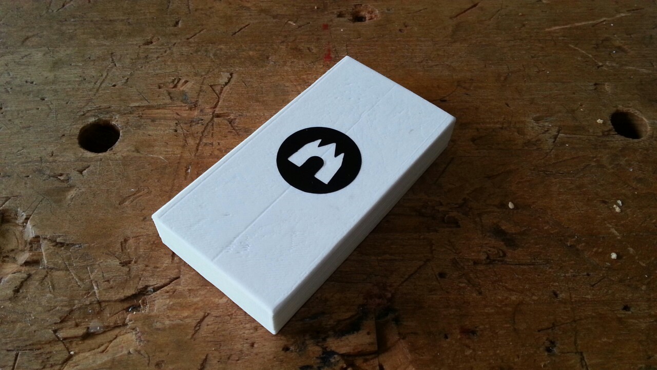
Sticker on the case
3) Assembling
As I completed to prepare the inside module and outside case as above, I started to assemble. First, the function of the device was a bit unstable becaues of the wire connection between boards were not good.

Unstable connection
So I made wires shorter and solderred neatly, coiled wires, and added blue insulator between board as below, so that I could put them into one case compactly.
Solderred proerly
Coiled wires compactly and added blue insulator
After several trial and error, I secceeded to assemble with maintaining its workability. The production image was below and it was a quite compact!
Assembled componnts
+) Final Presentation at Fablab Amsterdam
On following day, we gave the presentation at event room in Fablab Amsterdam, which had long history since Renbrant drew famous paints there. It was great honoer for me.
To give presentation briefly only within 2 minutes was a bit challenging because we had a lot to tell and deliver. However, it was a great experience and practice to give presentaiton to Niel, who is MIT professor, directly via video conference system.
I was very happy to hear Niel gave me the comment as 'Many people will want your device', and finished all the program of Fab Academy 2016.

Presentation room at Fablab Amsterdam
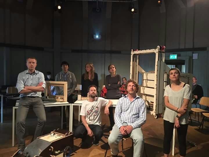
Members of Fab Academy 2016
3. For further improvement
Though I completed the device, it has only minimum function, for instance, I was not able to complete networking module. There are several points for further improvement as below;
- Minimize: The productoin was far from my satisfaction because it was too big to be portable. Next time, I would like to integrated threee boards to one board, and use smaller barttery and speaker, so that it become as small as I can put it into my wallet.
- Complete Networking and communication: I was not able to complete the smarthphone application side and networking module. Next time, I want to learn more and complete it.
- Prevent malfunction: Because of the sensitibity of accelerometer, the speaker sounds so frequently, actually without someone trying to steal it... So I have to solve this problem next time.
Outline of this page
0. Requirement for final project
1. Project Summary: 'ITEM WATCHMAN'
2-1. Project Development Process - electrical&programming part
2-2. Project Development Process - mechanical and assembling part
3. For further improvement
Download files
Here are my design files of my final project:
(electrical part)
-
Main microcontroller module: Fabkit(EAGLE):
schematic.SRC / board.BRD / trace.PNG / cutting.PNG holes.PNG - Input module: accelerometer board(EAGLE):
schematic.SRC / board.BRD / trace.PNG / cutting.PNG - Output module: speaker board(EAGLE):
schematic.SRC / board.BRD / trace.PNG / cutting.PNG
(mechanical(design) part)
- Plastic Case of the device(Fusion 360): Top.STL / Bottom.STL
- Decoration sticker(Inkscape): sticker.PDF
(programming part)
- software/arduino code: watchman.INO
Lecture Material for Final Project
Final Project Requirement
Checklist for Final project page
Have you made a separate 'Final Project' page that briefly summarises your project and:
- includes the BOM (Bill of Materials) for your project
- links to any weeks that you worked on your final project
- links to your presentation.png and presentation.mp4
- includes all of your design files in the archive
- (no external hosting of final project files - discuss file sizes with your instructor)
- Includes the licence you chose
Have you made your presentation.png (slide: 1280 x 1024 resolution) and included:
- your name
- the name of your project
- the name of the Fab Lab
- photo/render/sketch of your project
- a brief description of what your project is/does
Have you:
- made a ~1 minute (10MB/1080p) video of you explaining your project