Wk13: 2016/04/27
OUTPUT DEVICES
0. Assignments for wk13
The assignments for wk13 were as below;
- Add an output device to a microcontroller board you've designed and programme it to do something.
1. Making Speaker Board
For the assignment of this week, I decided to make the speaker board which I can add it to Fabkit, which I made Input Device week since I have to implement the speaker module to my final project.
Designing the board
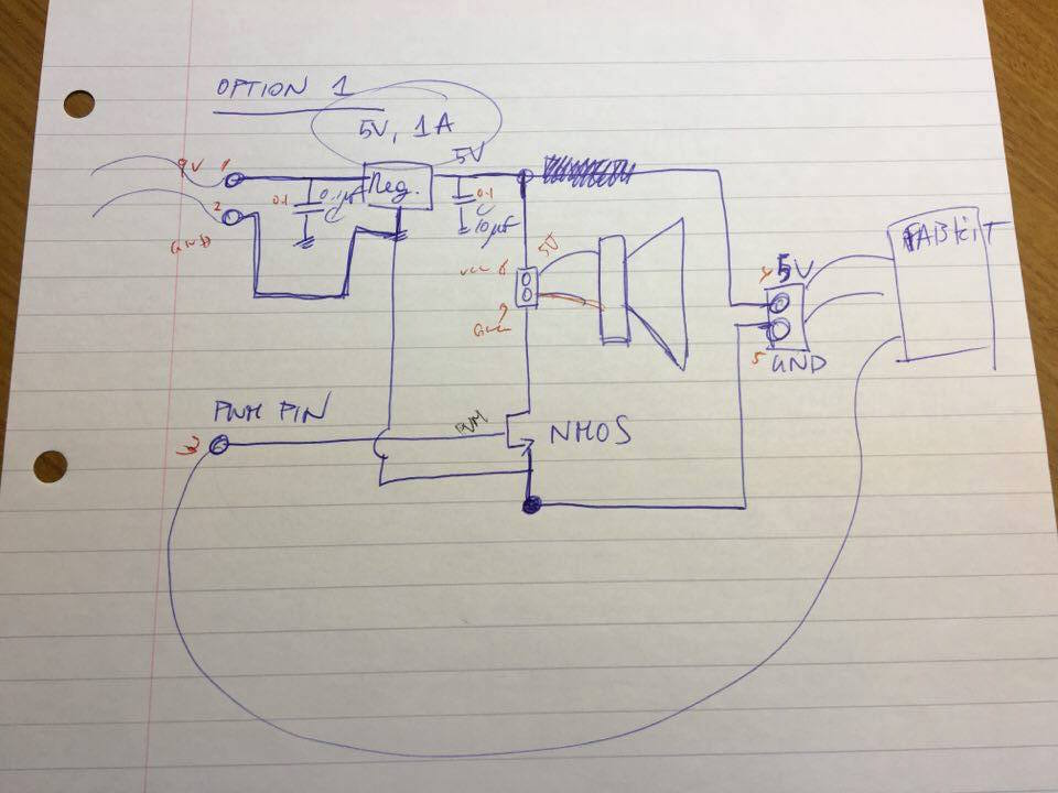
First, we made a lough sketch of the schematic with a lot of help by Emma. The challenge was that I had to add reguralor to decrease the voltage because the appropriate voltage for Fabkit was mainly 5V, however, that for the speaker module was 9V.
Therefore, I added a 5V and 1A regulator to down the voltage from 9V to 5V and two capacitors to stabilize the current as the sketch below with reffering the datasheet of Regulator: LM2940C.
Designing the board on Eagle
After fixing the hand-written schematic, I wrote the schematic on EAGLE. However, I made several mistakes in this designing step.
Mistake1: Wrong Connection
Fisrt, I wrote the schematic following the concept sketch above, and milled the board, solderred parts, however, it did not work in the end.
After several debugging I found that I made mistake when I wrote the schematic; I forgot to PIN NHOS as below. This error created one trash in this world...
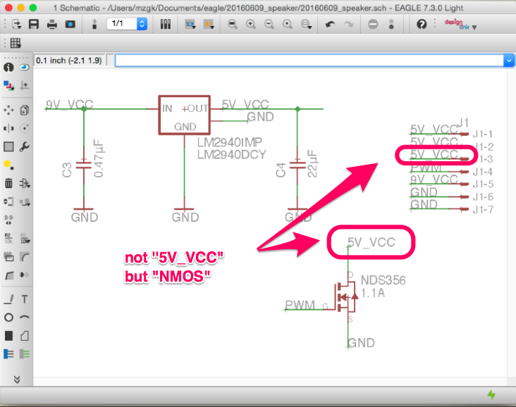
Wrong schematic of speaker board
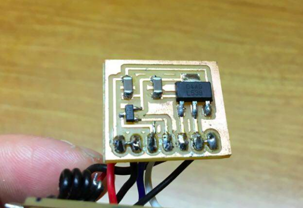
Mistake2: Wrong MOSFET
Next mistake was to use the wrong MOSFET, which was a voltage controlled field effect transistor .
There were two MOSFET in the inventory in Fablab Amsterdam.
Though I should have used MOSFET of
N-Channel in this project, I wrongly used P-Channel parts on the board as below. So I have to change the schematic and the my inventory.

Wrong board with MOSFET of wrong direction
Production
After several trial as above, I finished designing the right schematic and the board as below.


Finally, I exported PNG file for tracing and cutting by modela as below and finished the designing part.

20160609_speaker_trace_v4.png

20160609_speaker_cut_v4.png
Soldering the parts to the board
After that, The soldering part was also finished straigtforward. Here is the speaker board which I made.
Writing the code
Next, I wrote the test code on Arduino for checking if the speaker board were working correctlly or NOT as below.
#define BEAT 300   // define the length of the sound
#define PINNO 2   // Pin number

void setup() {
}
void loop() {
     tone(PINNO,262,BEAT) ;  // C
     delay(BEAT) ;
     tone(PINNO,294,BEAT) ;  // D
     delay(BEAT) ;
     tone(PINNO,330,BEAT) ;  // E
     delay(BEAT) ;
     tone(PINNO,349,BEAT) ;  // F
     delay(BEAT) ;
     tone(PINNO,392,BEAT) ;  // G
     delay(BEAT) ;
     tone(PINNO,440,BEAT) ;  // A
     delay(BEAT) ;
     tone(PINNO,494,BEAT) ;  // B
     delay(BEAT) ;
     tone(PINNO,523,BEAT) ;  // C
     delay(3000) ;           // Repeat after 3 seconnds
}
Production
Then finally, I was able to get sounds from the speaker, and successfuly made the baord.
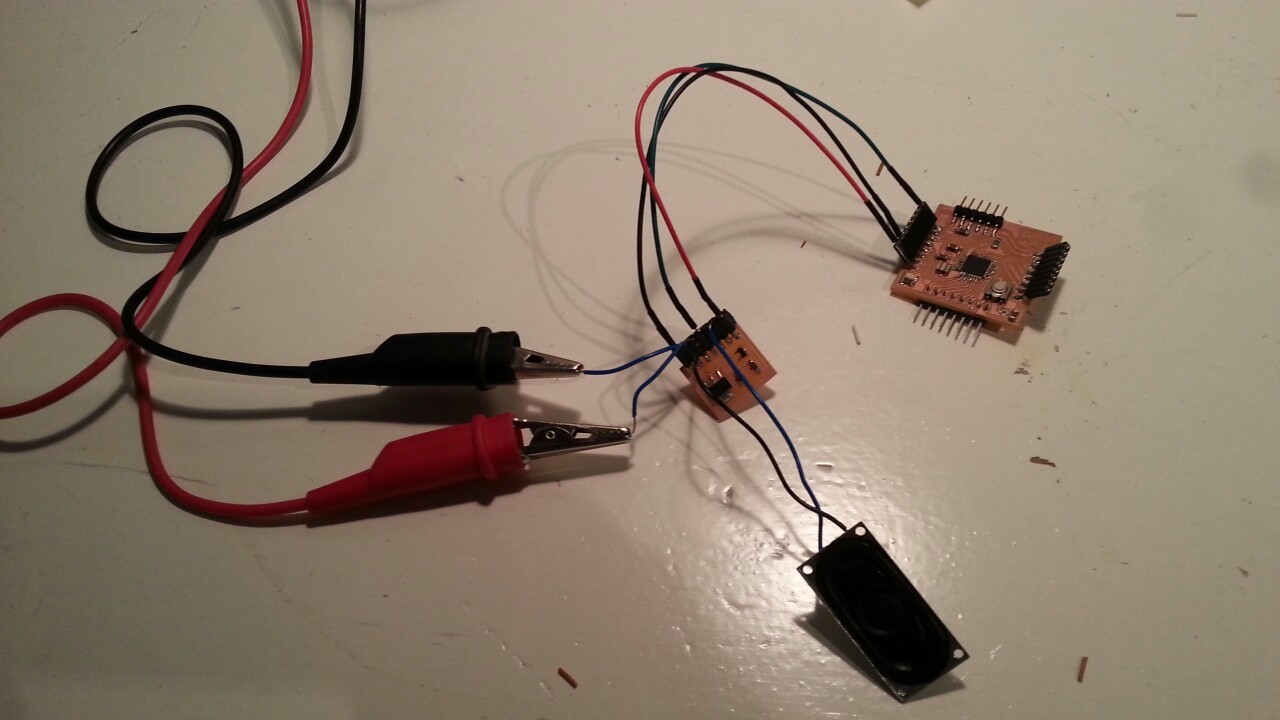
Speaker board with external battery
VIDEO(1): Speaker board with FTDI
Also, it worked not with FTDI cable but with external battery, and I could got good progress on my final project.
VIDEO(2): Speaker board with external battery
Outline of this page
1. Making Speaker Board
Download output of Wk13
Here are my output files for wk13:
(Speaker board)
(Programming)
Lecture Material for Wk13
Lecture Note
Tools
- Arduino
- FTDI cable
- EAGLE
Videos of Wk13
Here you can find this weeks's lectures on VIMEO:
(2016.04.27)
(2016.05.04)
Checklist for Wk13
Assignments:
- Add an output device to a microcontroller board you've designed and programme it to do something.
Learning outcomes:
- Demonstrate workflows used in circuit board design and fabrication
- Implement and interpret programming protocols
Have you:
- Described your design and fabrication process using words/images/screenshots.
- Explained the programming process/es you used and how the microcontroller datasheet helped you.
- Outlined problems and how you fixed them
- Included original design files and code