About me
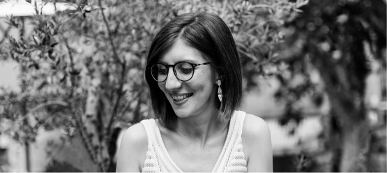
Hello, my name is Lucia Simeoni, I'm from Bastia (Corsica) and I'm 27 years old. I graduated in product design and interior architecture from L'Institut Supérieur des Arts Appliqués (LISAA), Paris in 2012. During my course at LISAA, I did a summer internship at Aldo Cibic Design in Vicenza, Italy. I’m a product designer but I also have an inclination for #iot and I'm a robotics enthusiast. Early in 2015, I launched my own online design shop: pavoneplace.com. I am the project manager and the designer in a team of 3. From July to Decembre, I worked as a FabManager at FabLab Corti, the FabLab of the University of Corsica. I've been hired at the time of the pre-opening phase. During the summer, we ordered the machines and we started creating a community through social medias. We also started public relations in some local medias. The FabLab have a strong focus on design. This job was an opportunity for me to combine two important interests: IT and design. Now, I'm working in freelance at RobotiCamp, a robotics school in Corsica. I'm managing the front office and I'm writing lessons for the little students.
Contact: luciamsimeoni@gmail.com
Instagram+Twitter: @loodgia
Linkedin: linkedin.com/luciasimeoni
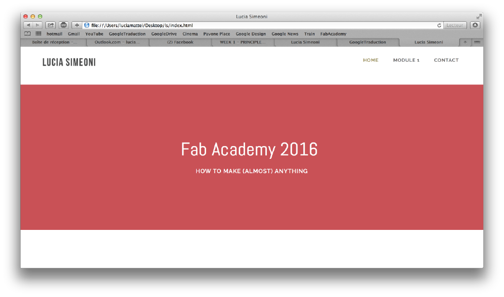
FINAL
PROJECT
Presentation
WEEK 18
Projet Development
Weeks
WEEK 17
Invention, Iproperty and business models
WEEK 16
Applications and implications

WEEK 15
Interface and application programming

WEEK 14
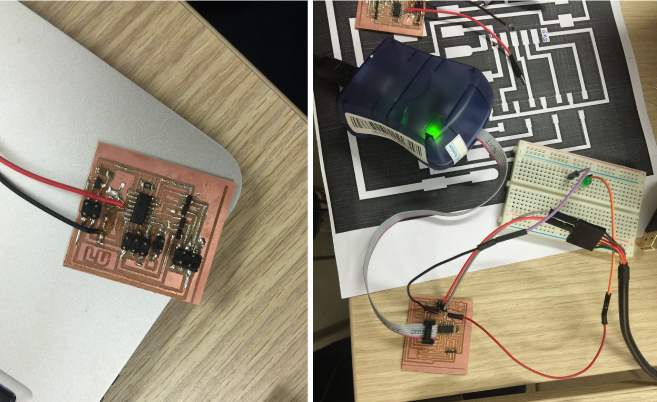
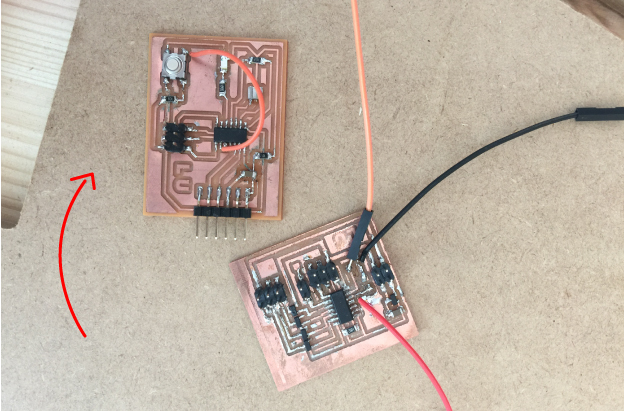
Networking and communications

WEEK 13
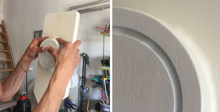
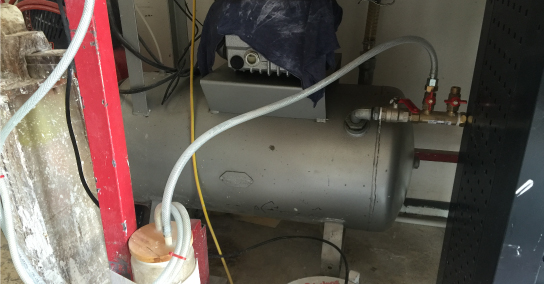
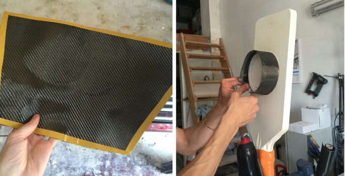
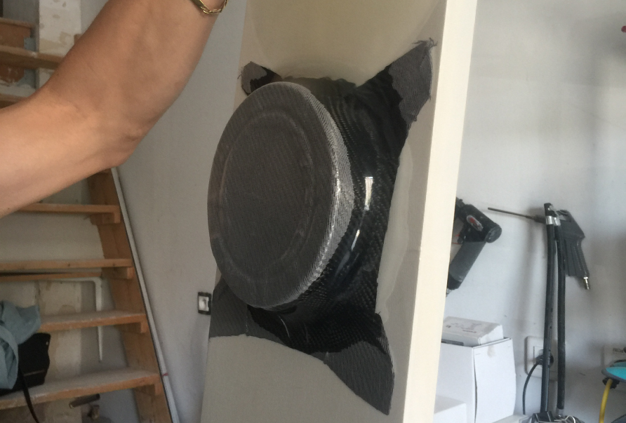
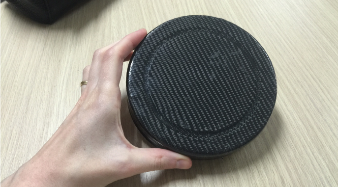
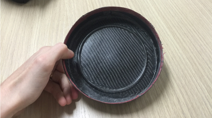
Composites
WEEK 12
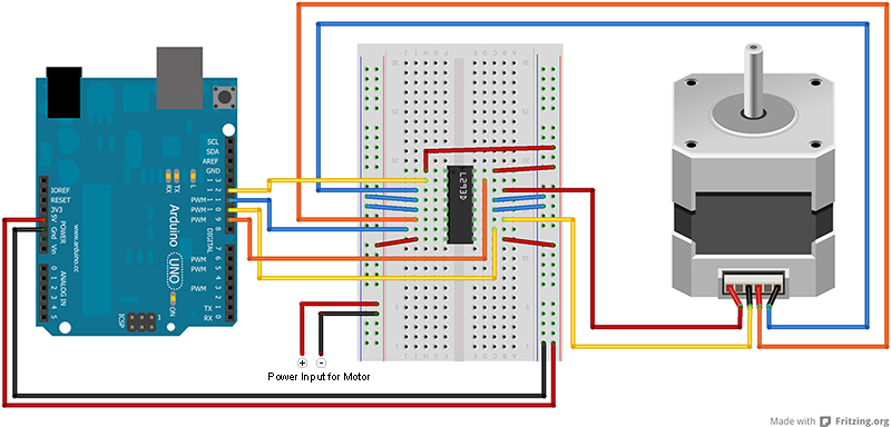
Output Devices
WEEK 11
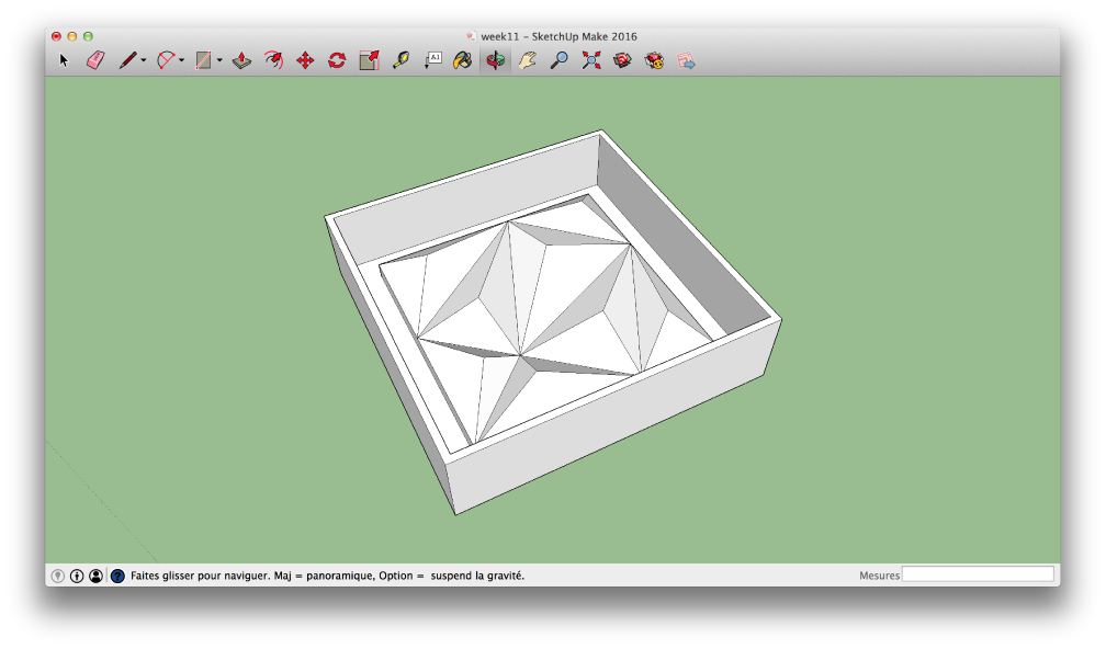
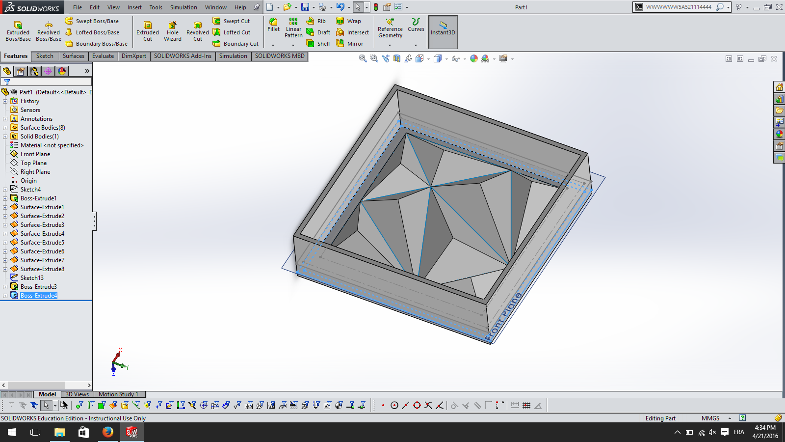
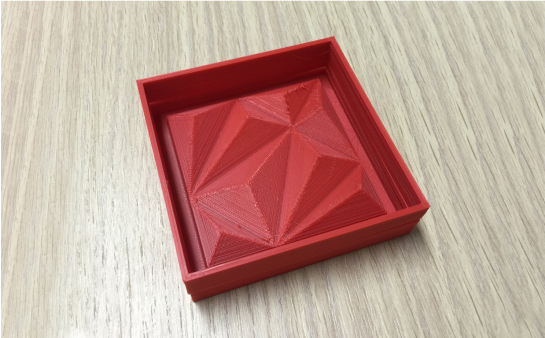
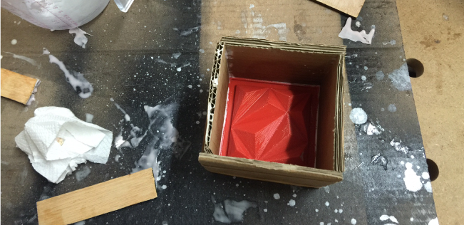
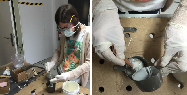
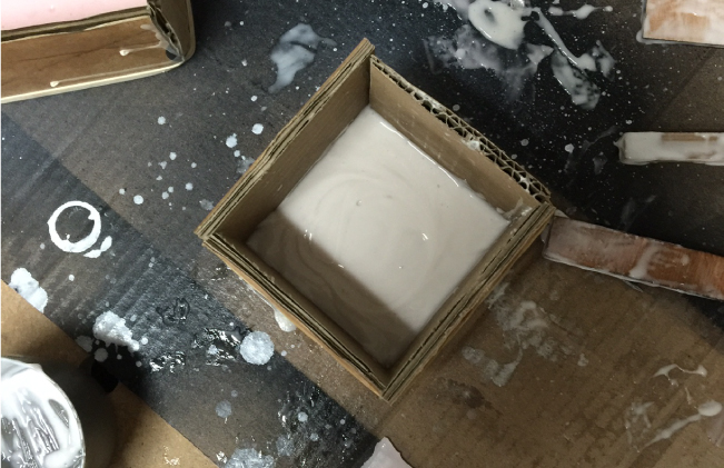
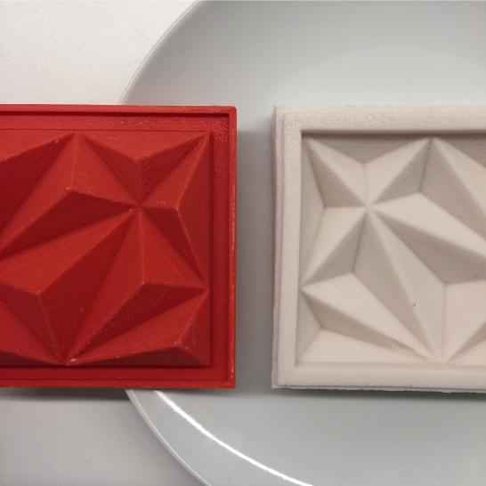
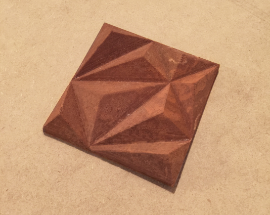
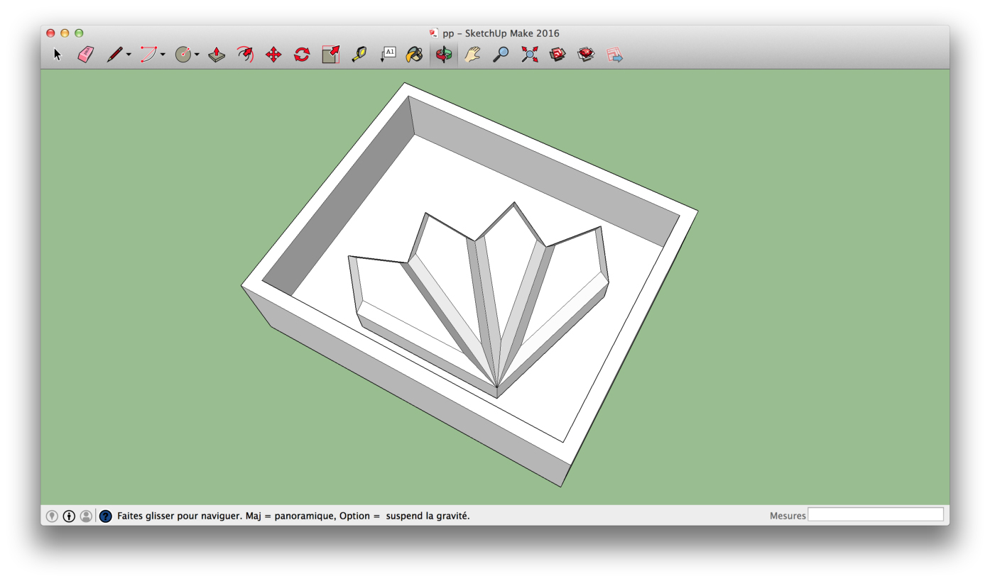
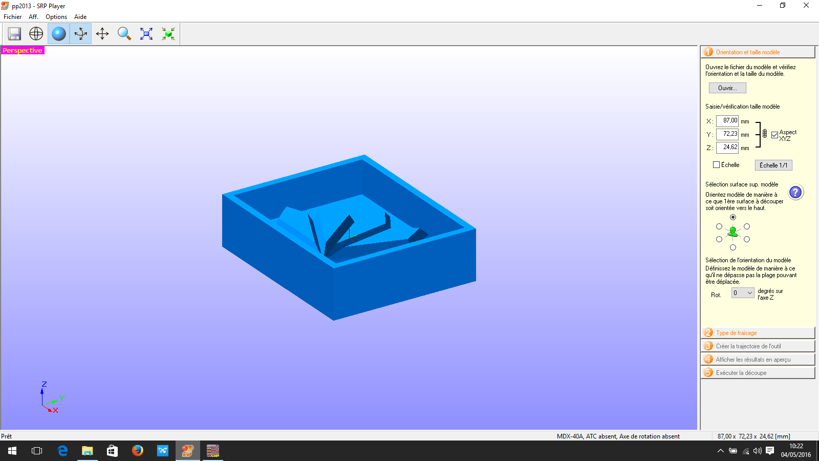
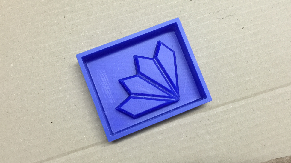
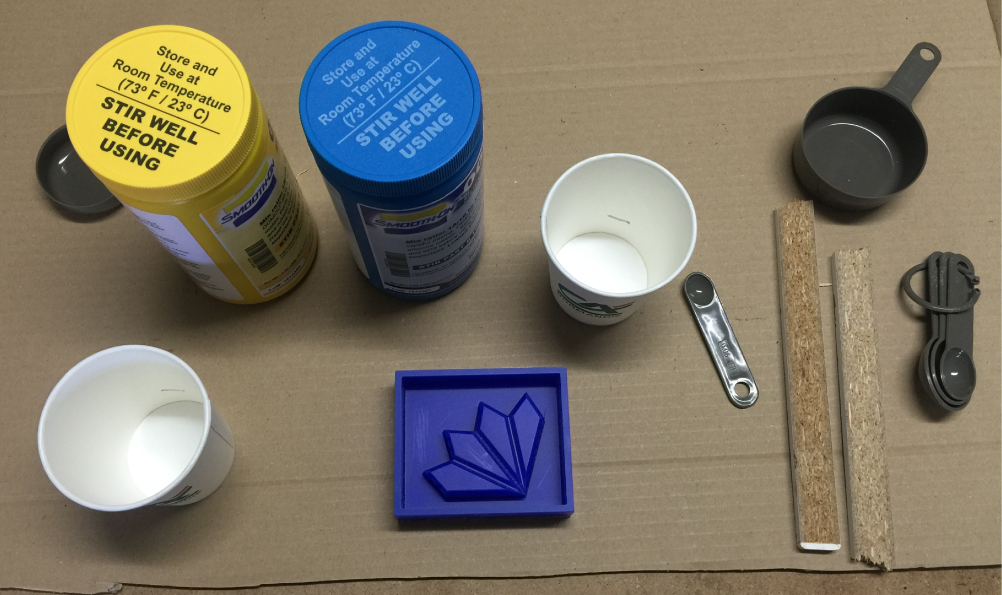
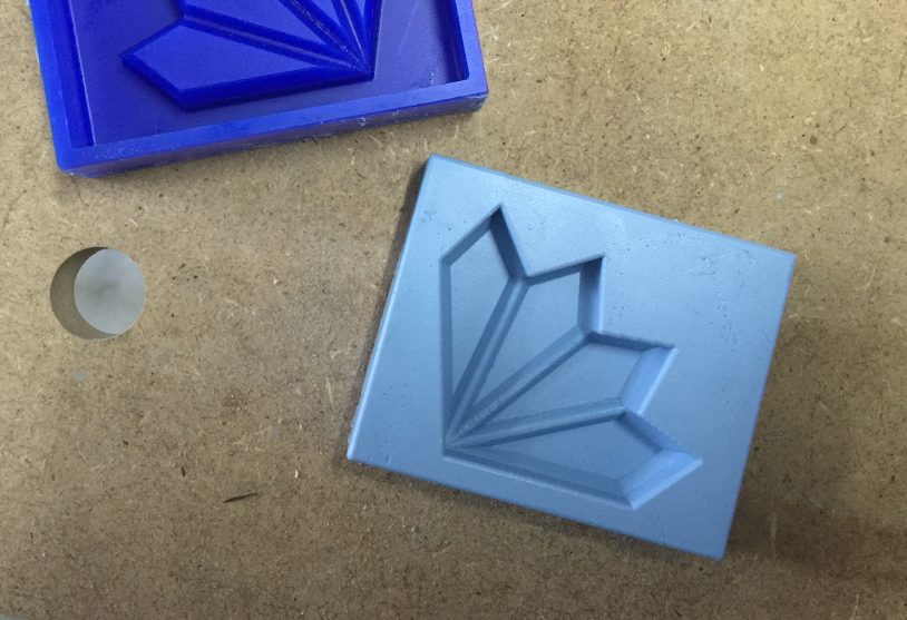
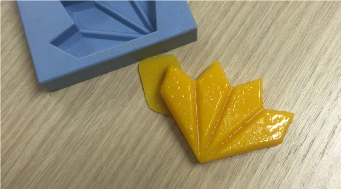
3D Moulding and casting

WEEK 10
Input Devices
WEEK 9
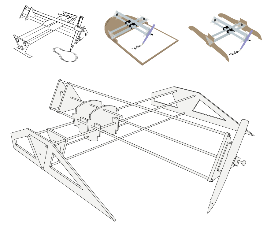
Mechanical and machine design

WEEK 8
Embedded programing
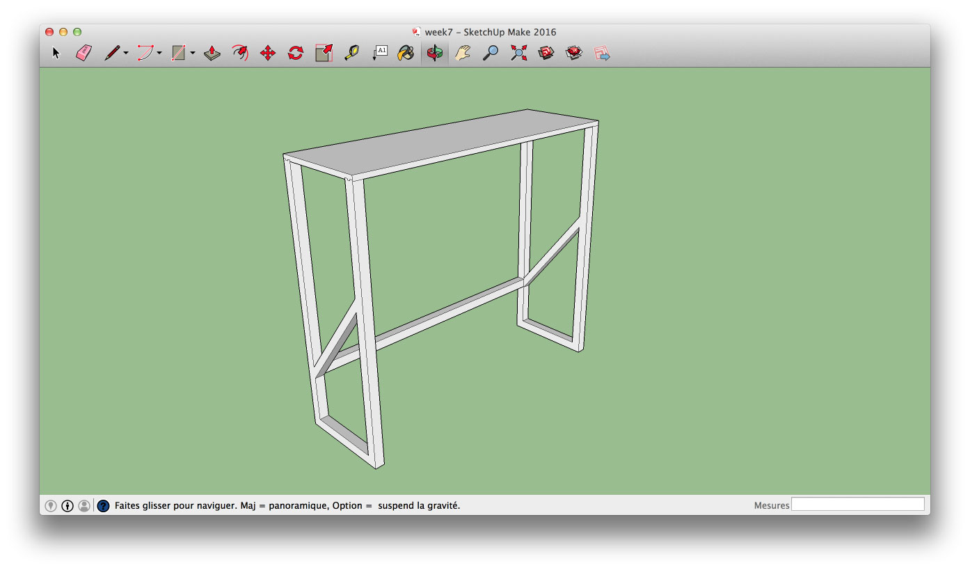
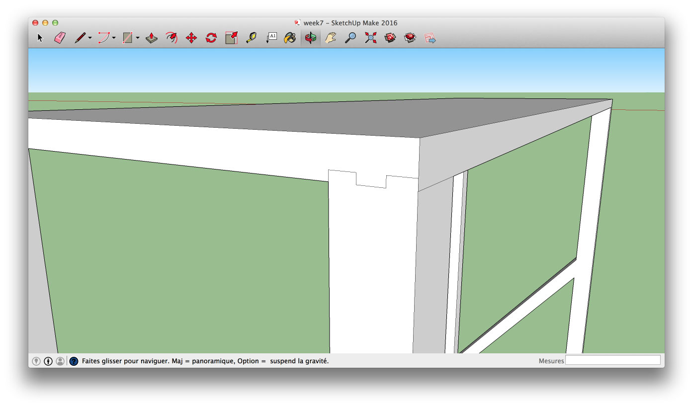
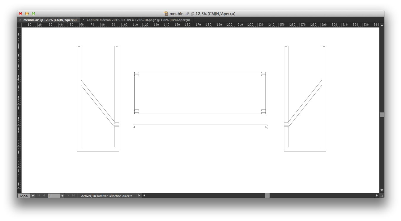
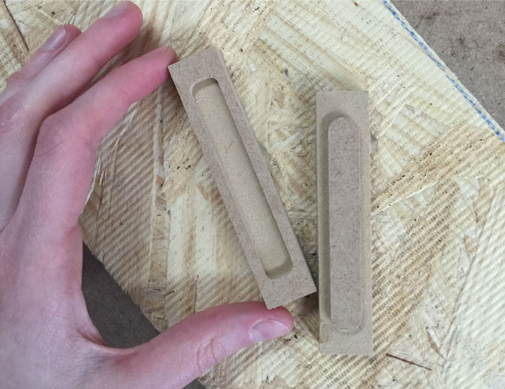
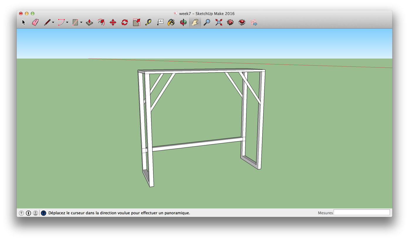
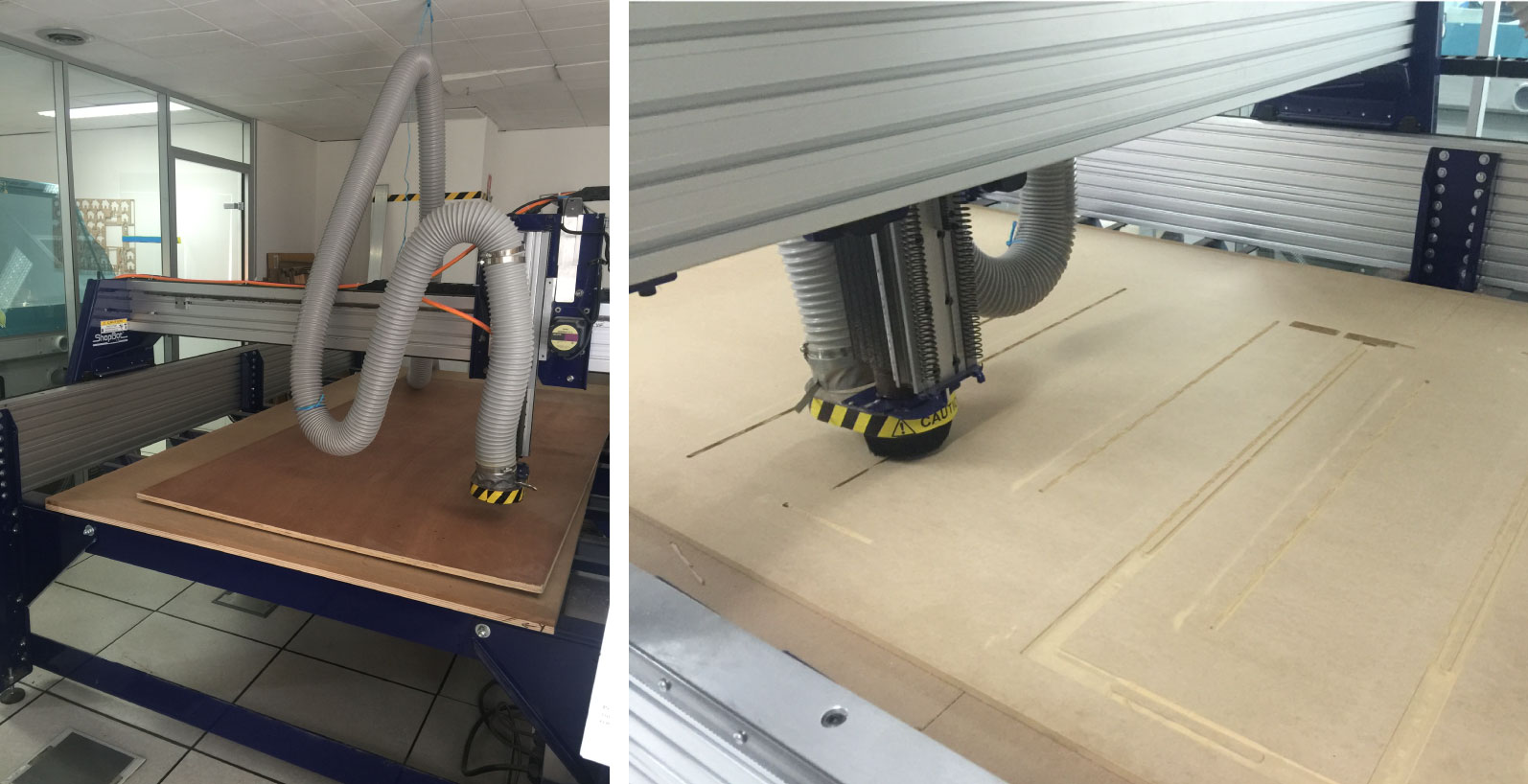
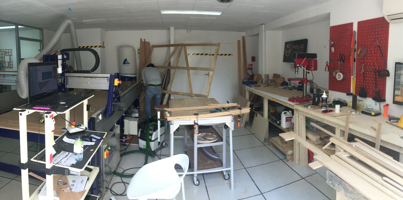
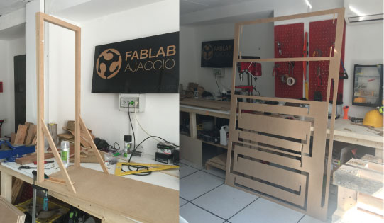
WEEK 7
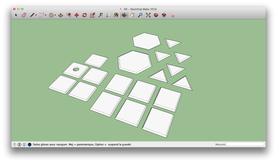
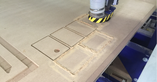
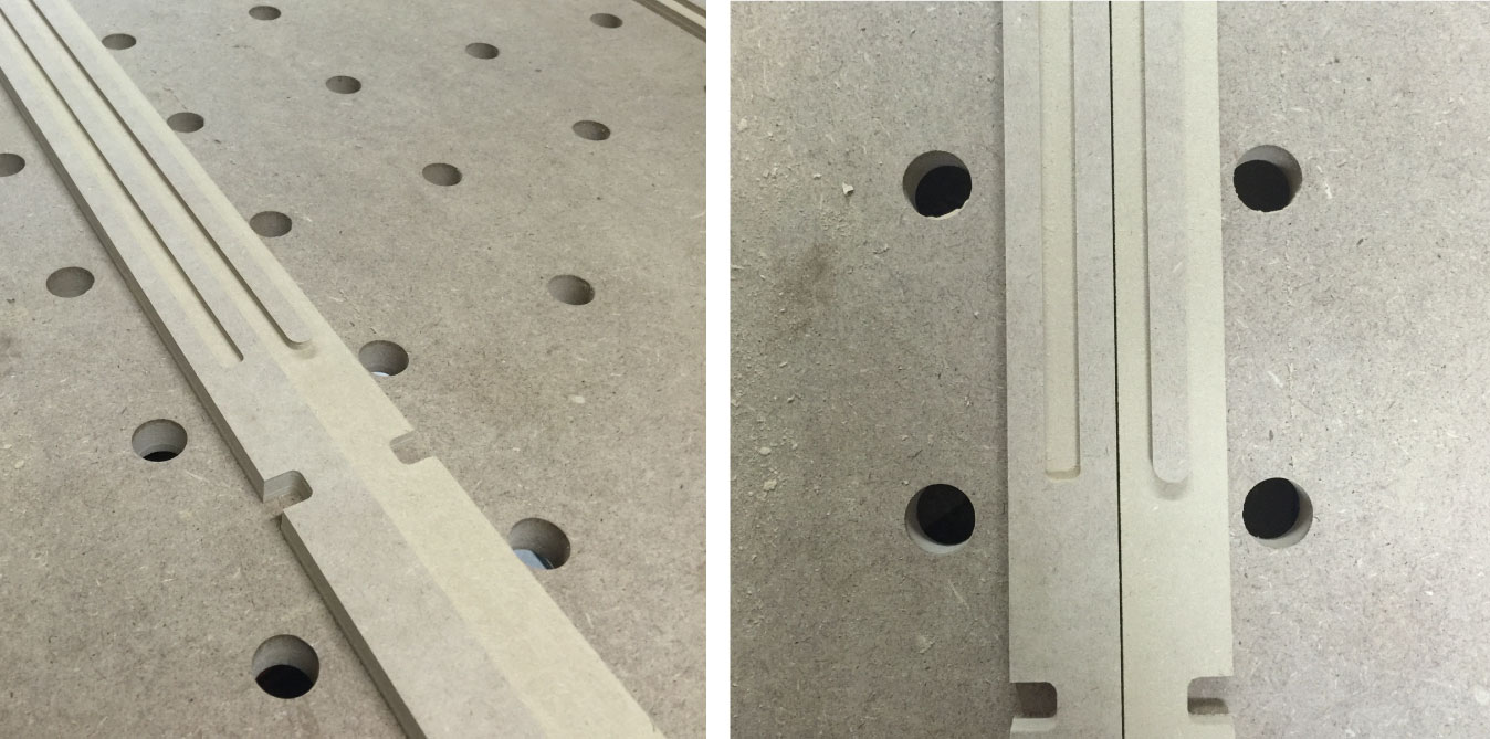
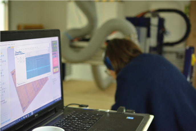
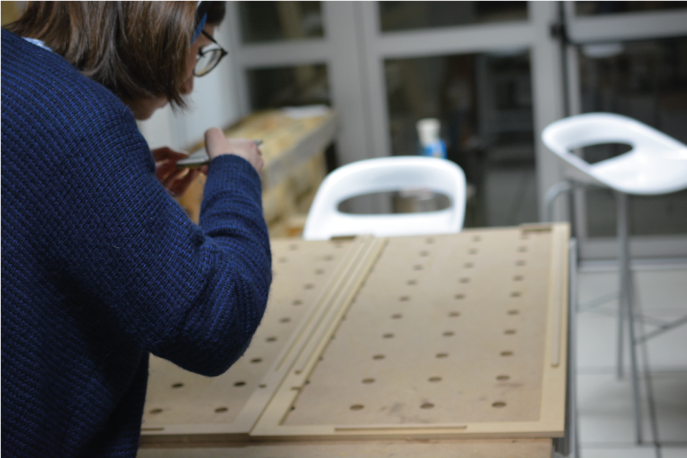
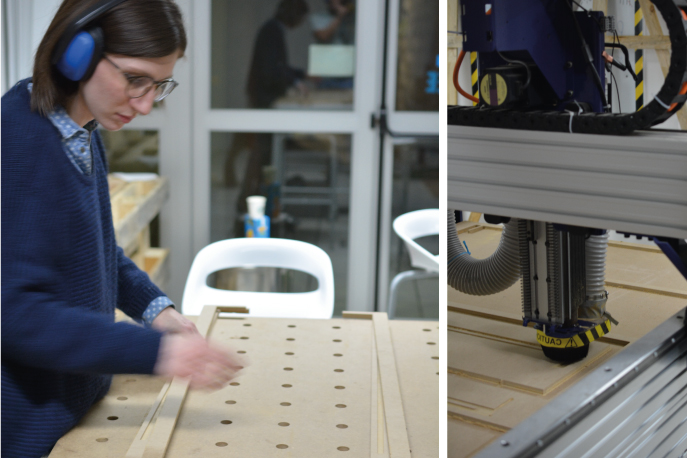
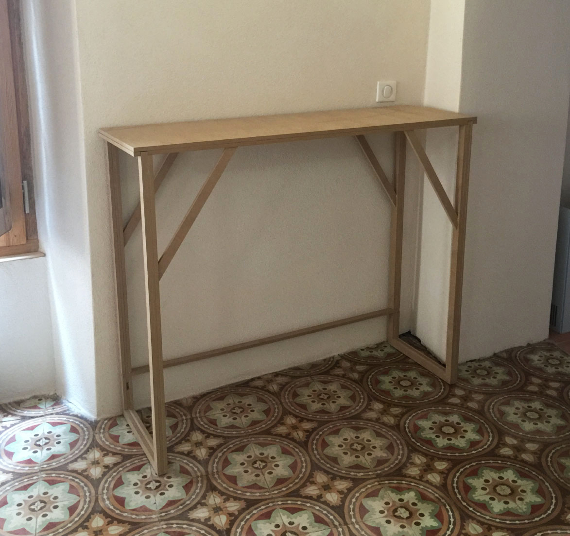
Computer-Controlled Machining
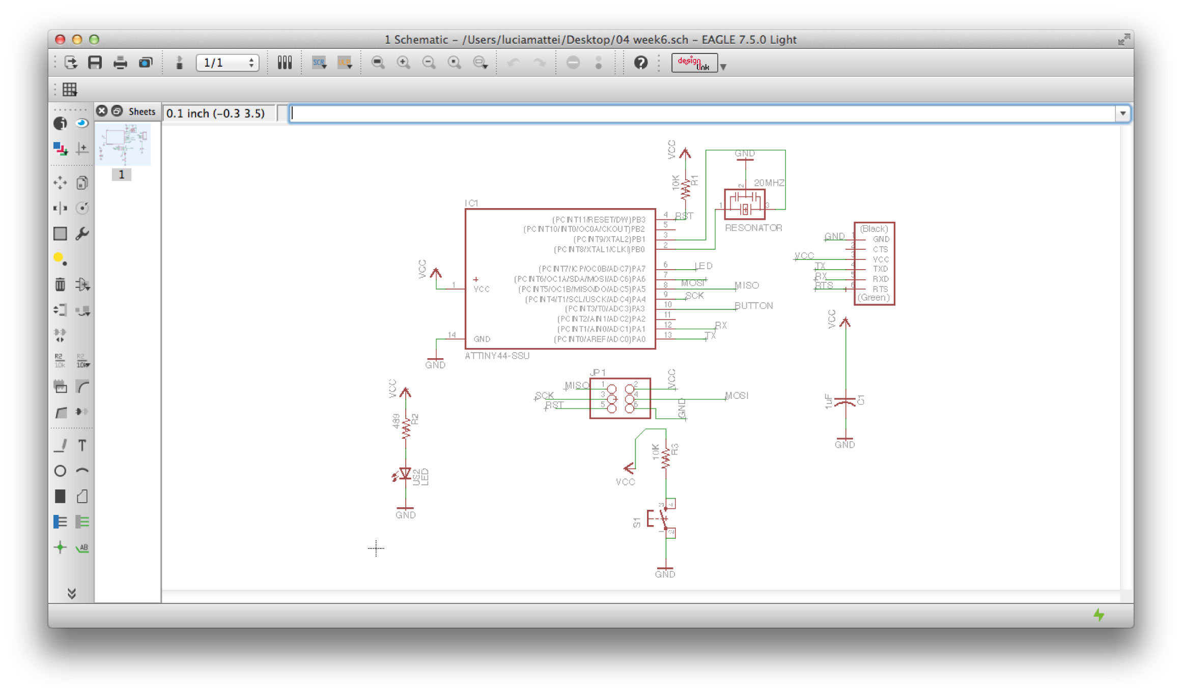
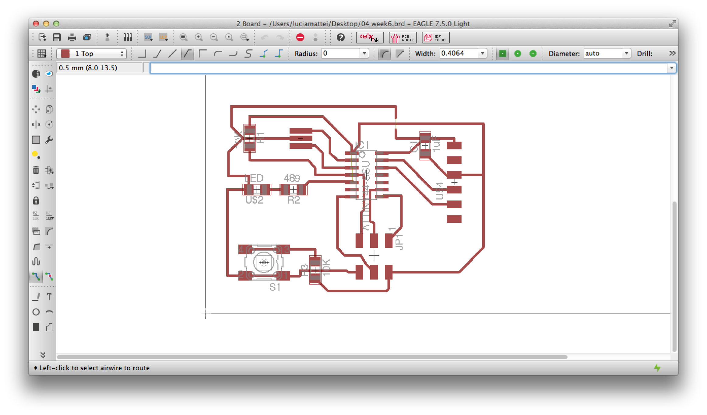
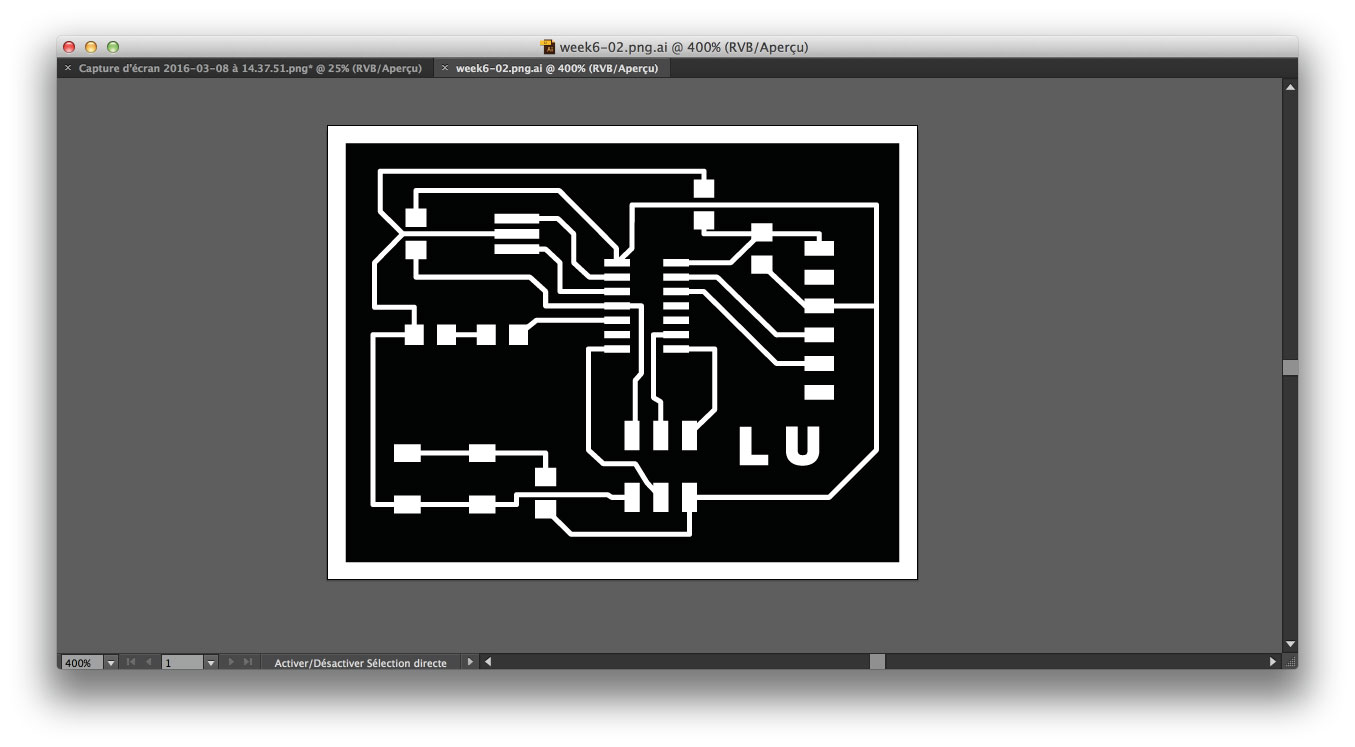
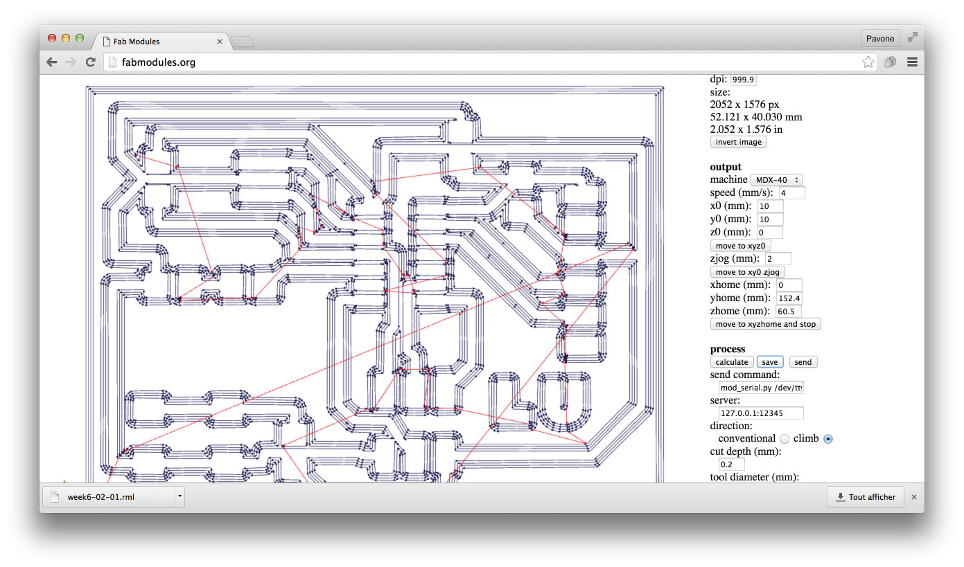
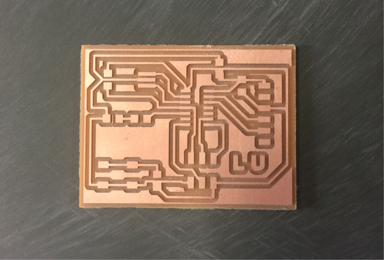
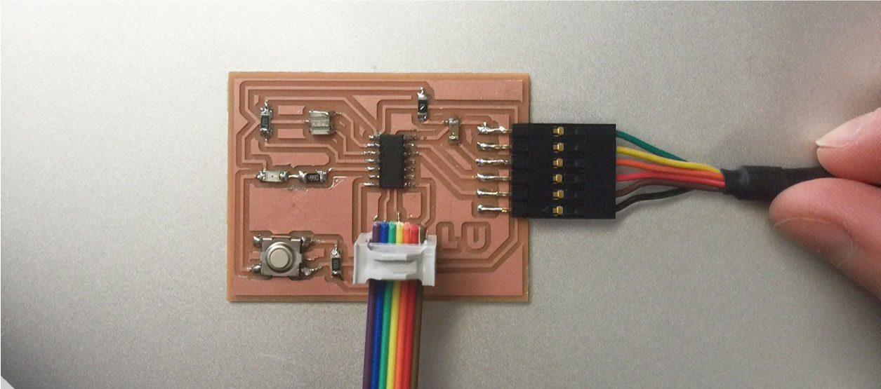
WEEK 6
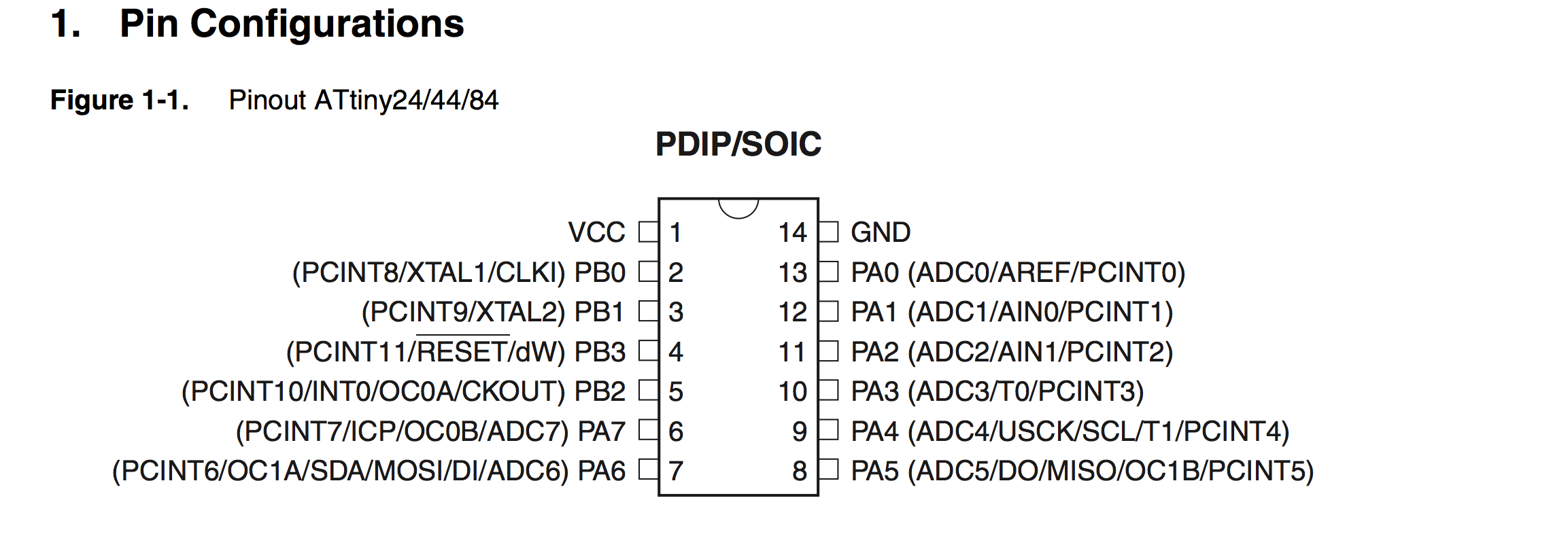
Electronics Design
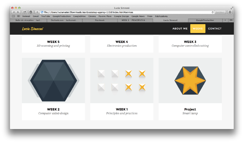
WEEK 5
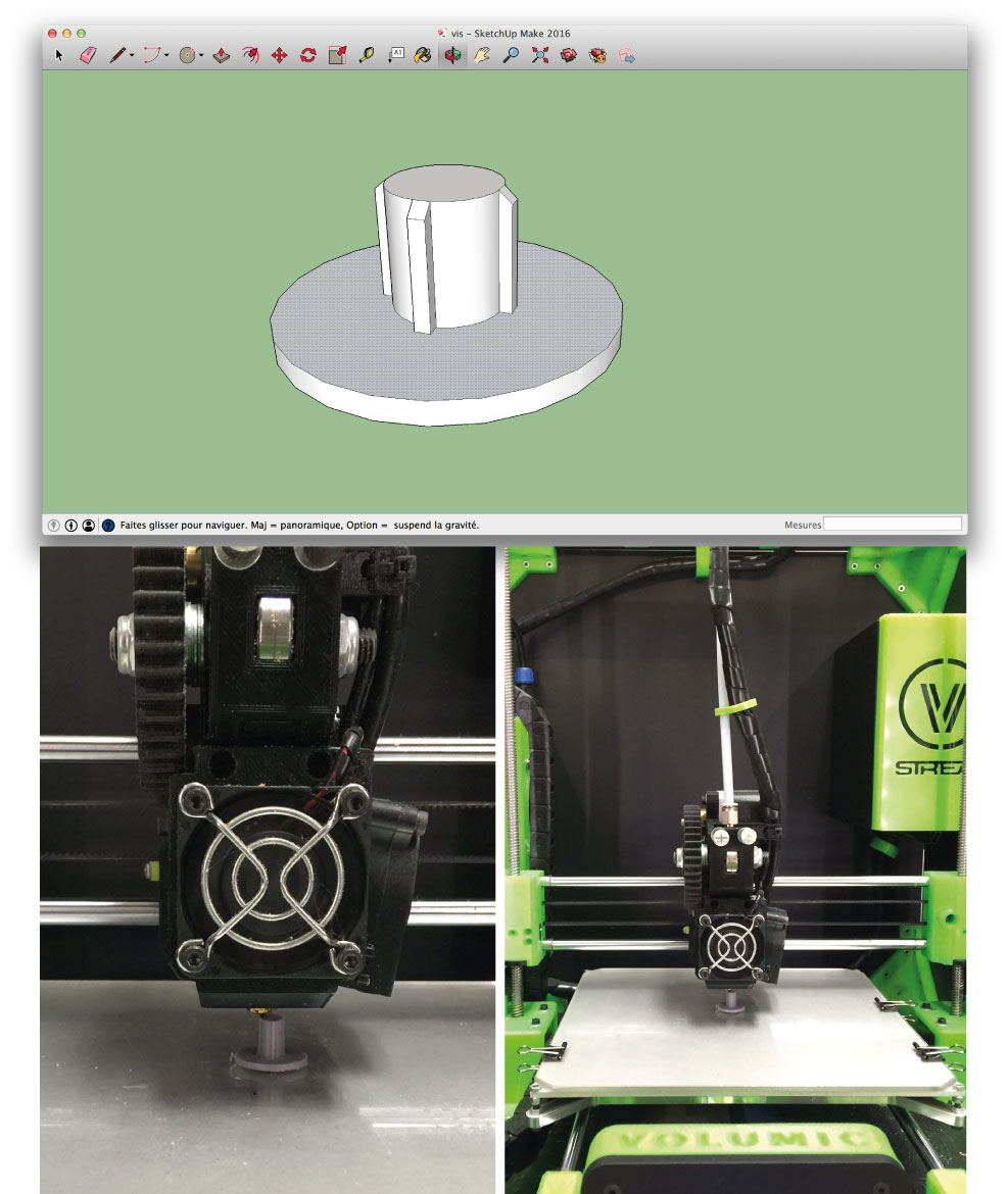
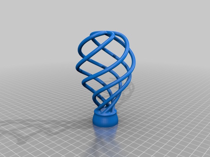
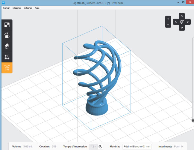
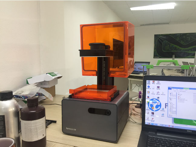
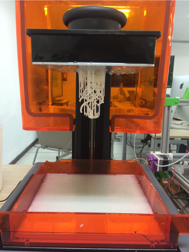
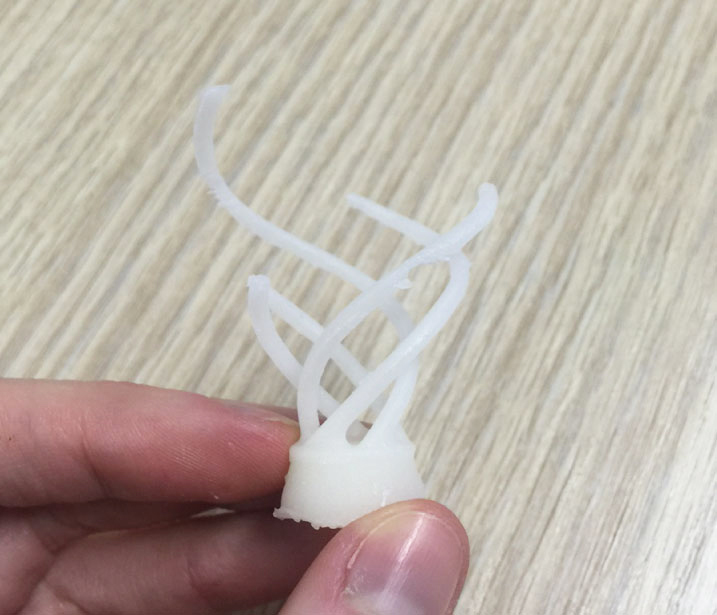
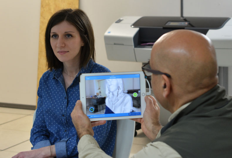
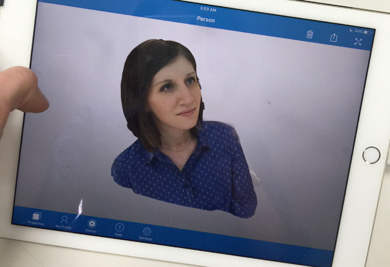
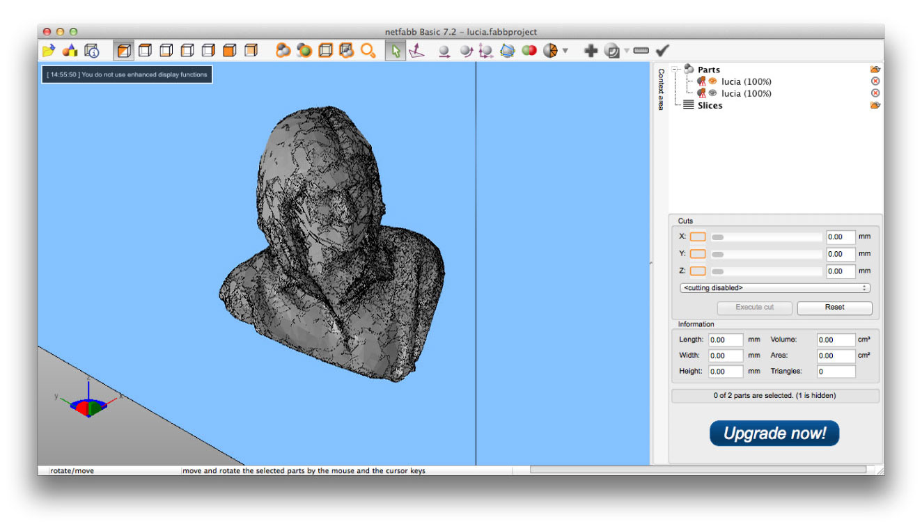
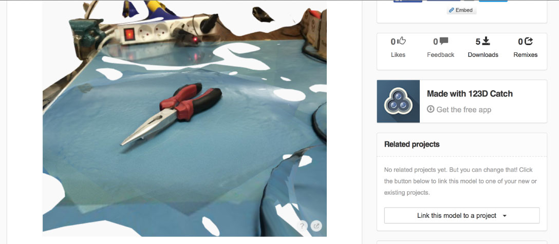
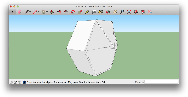
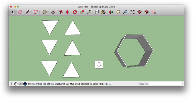
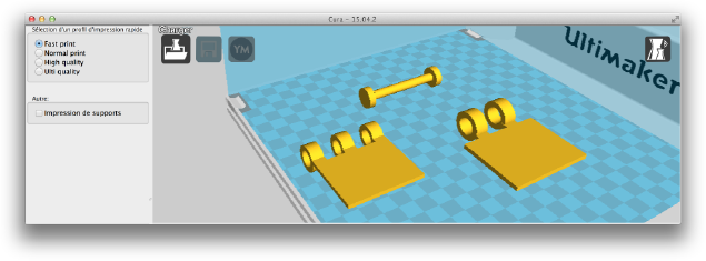
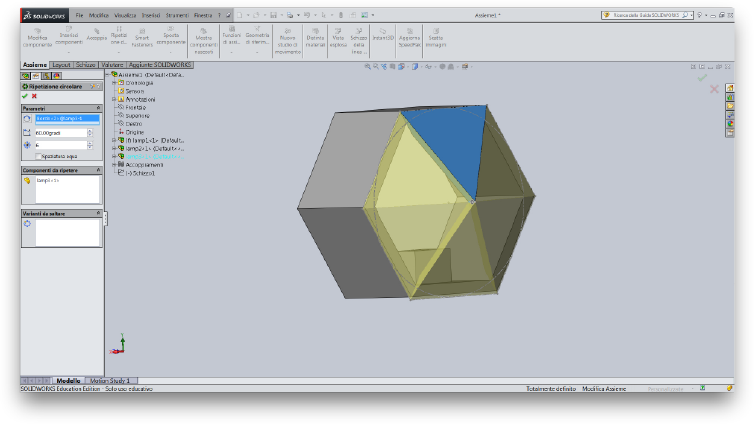
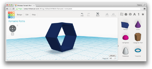
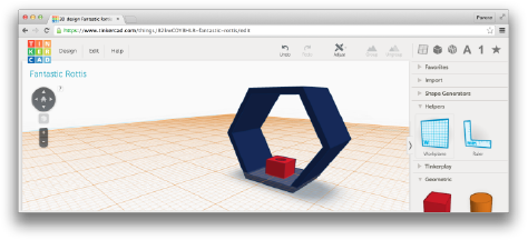
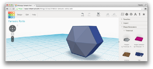
3D scanning and printing
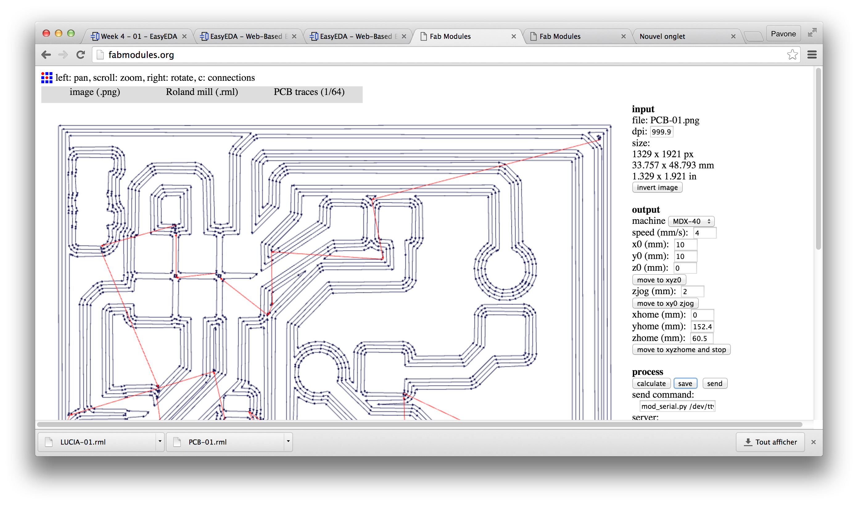
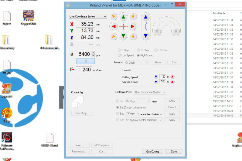
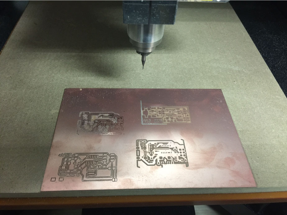
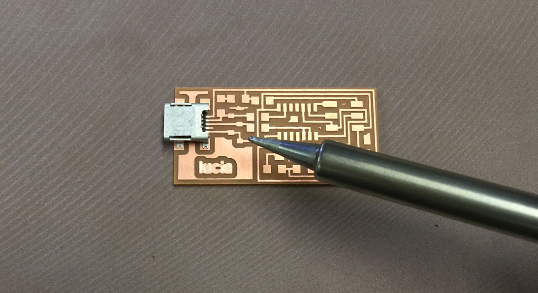
WEEK 4
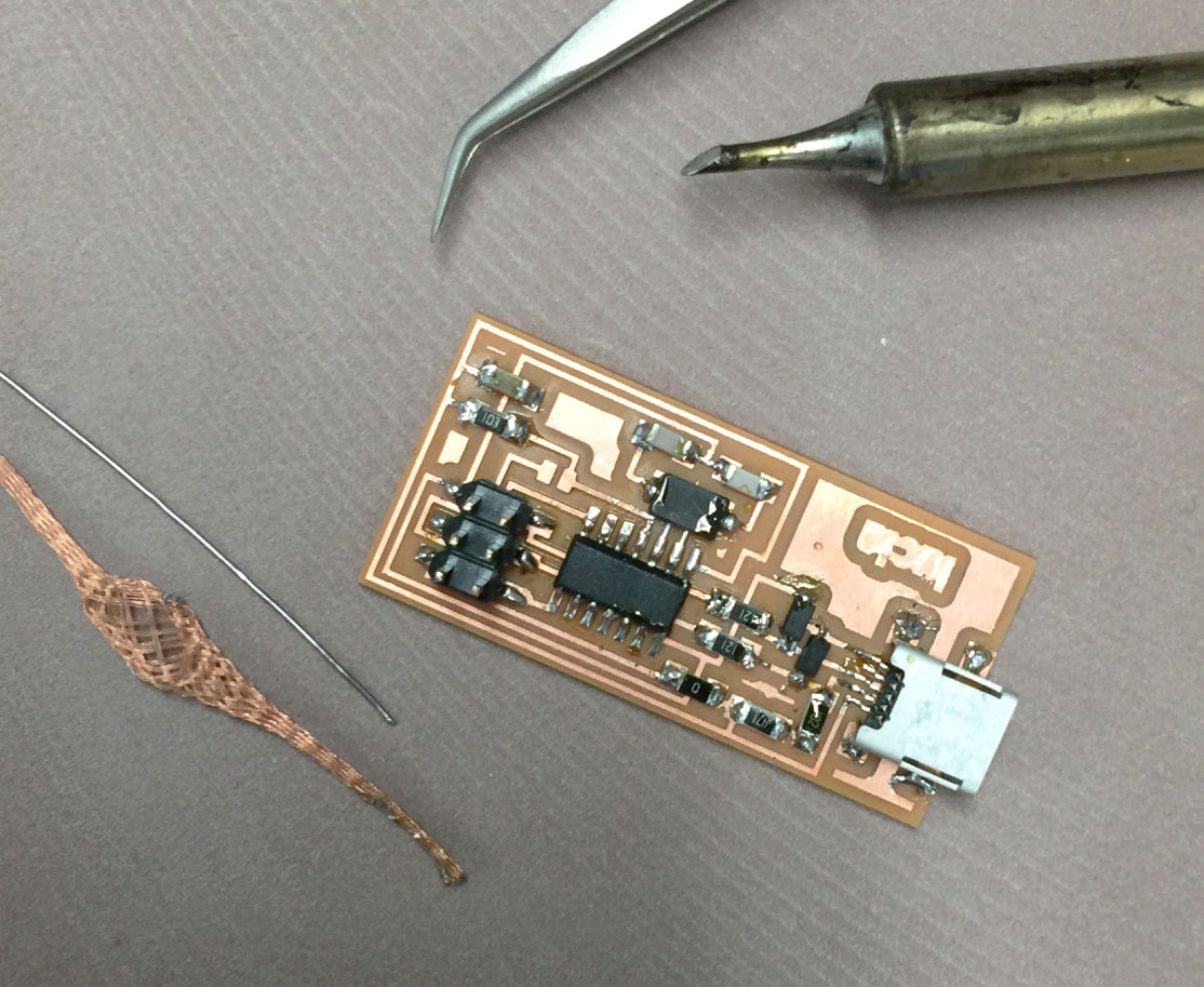
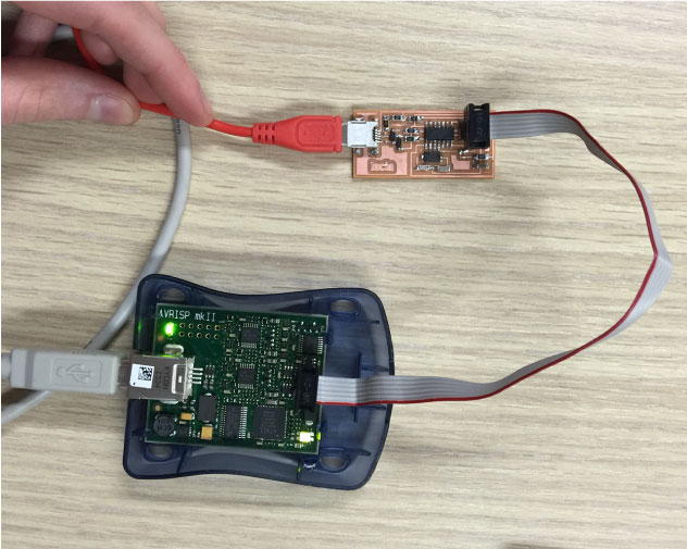
Electronics production
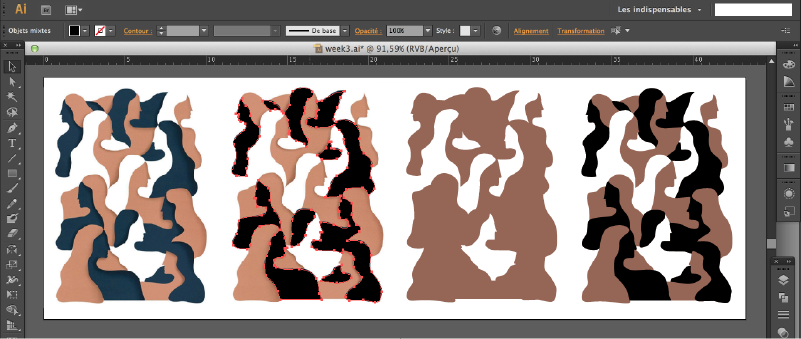
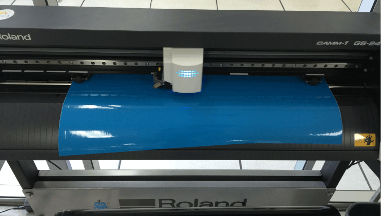
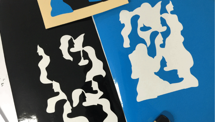
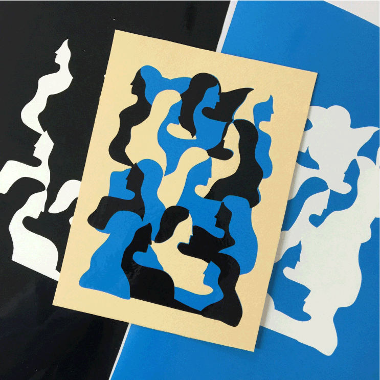
WEEK 3
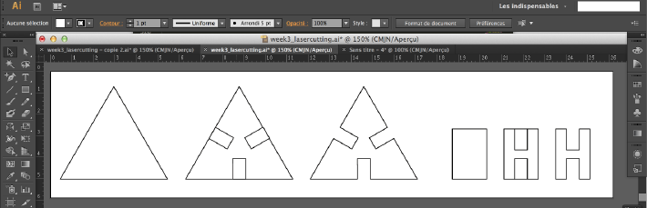
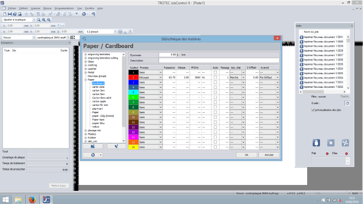
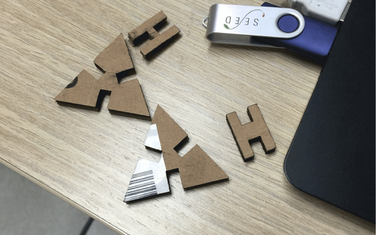
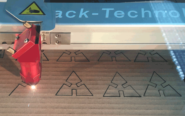
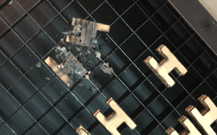
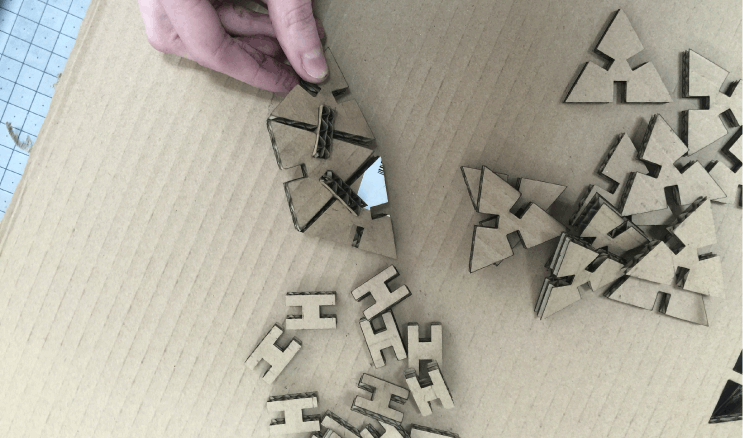
Computer controlled-cutting
WEEK 2
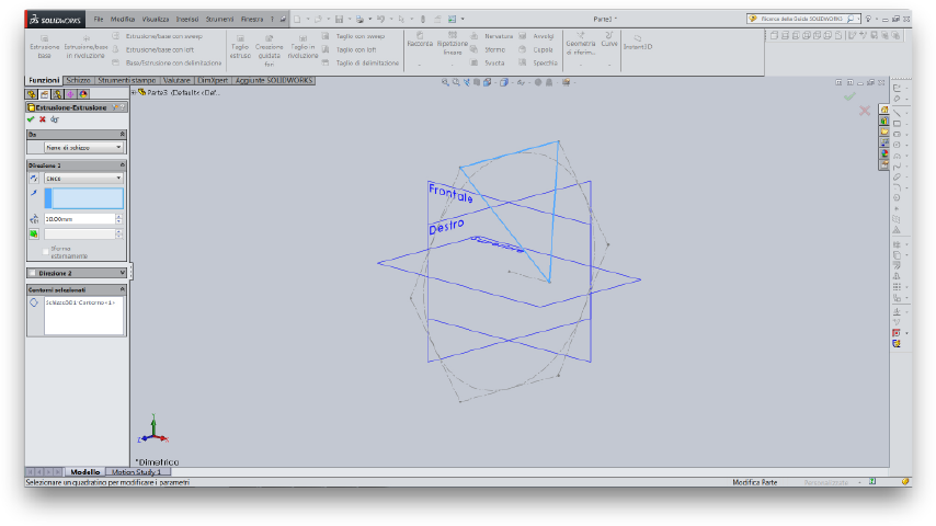
Computer aided-design
WEEK 1
Principles and practices

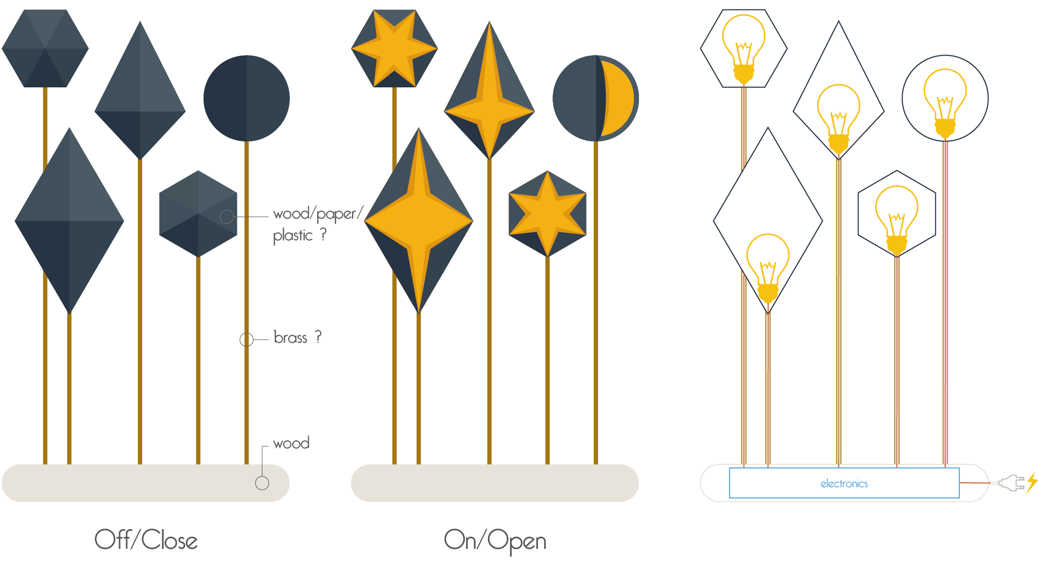
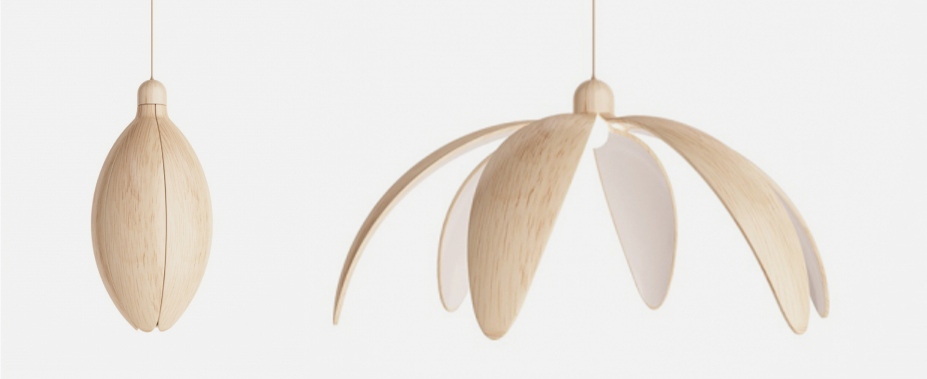
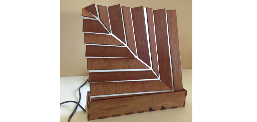
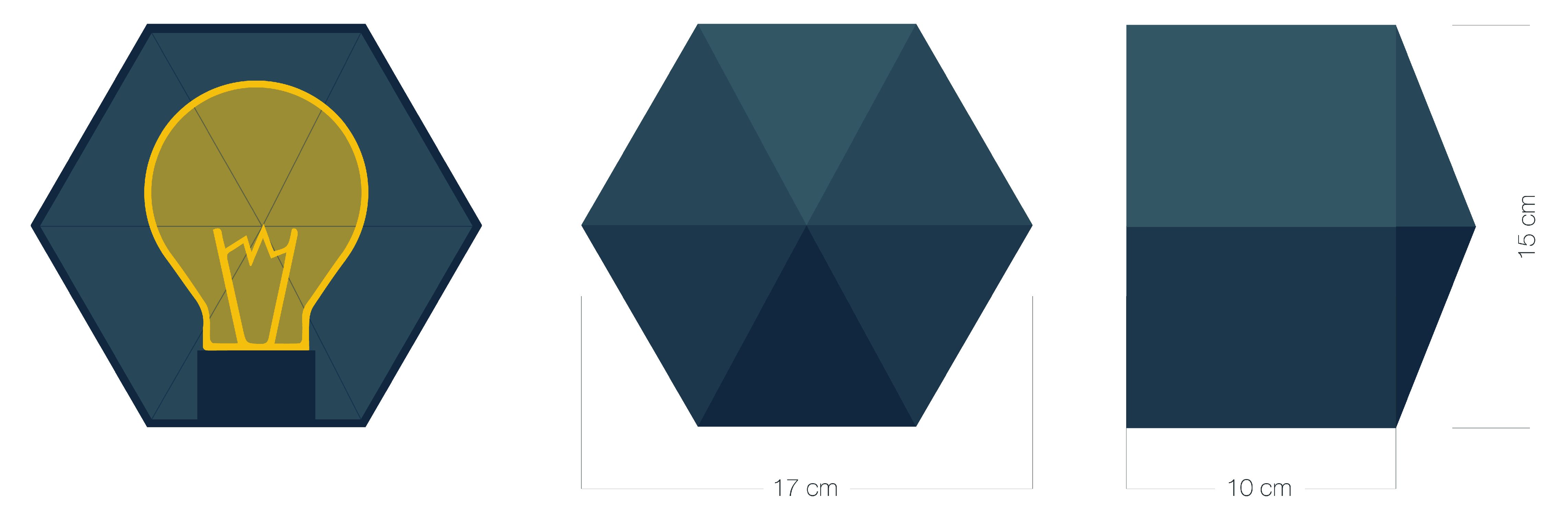
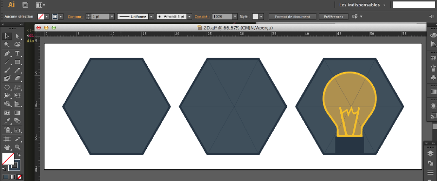
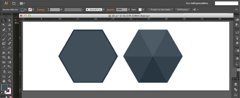
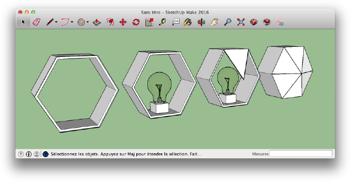
Project
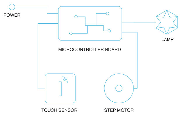
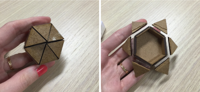
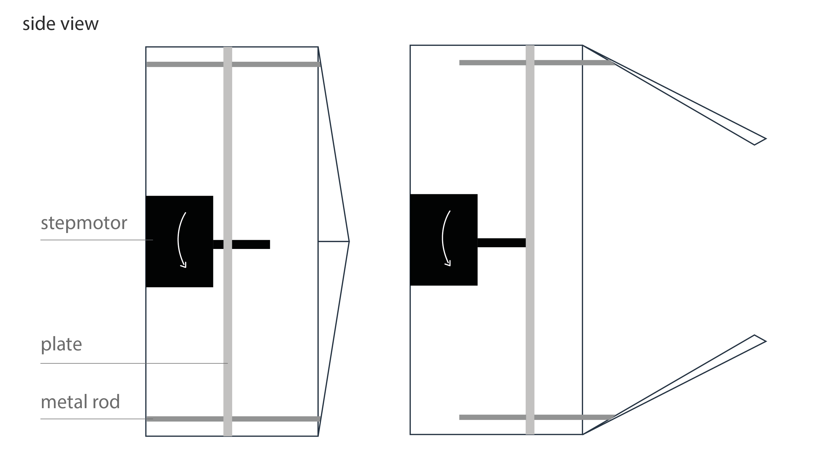
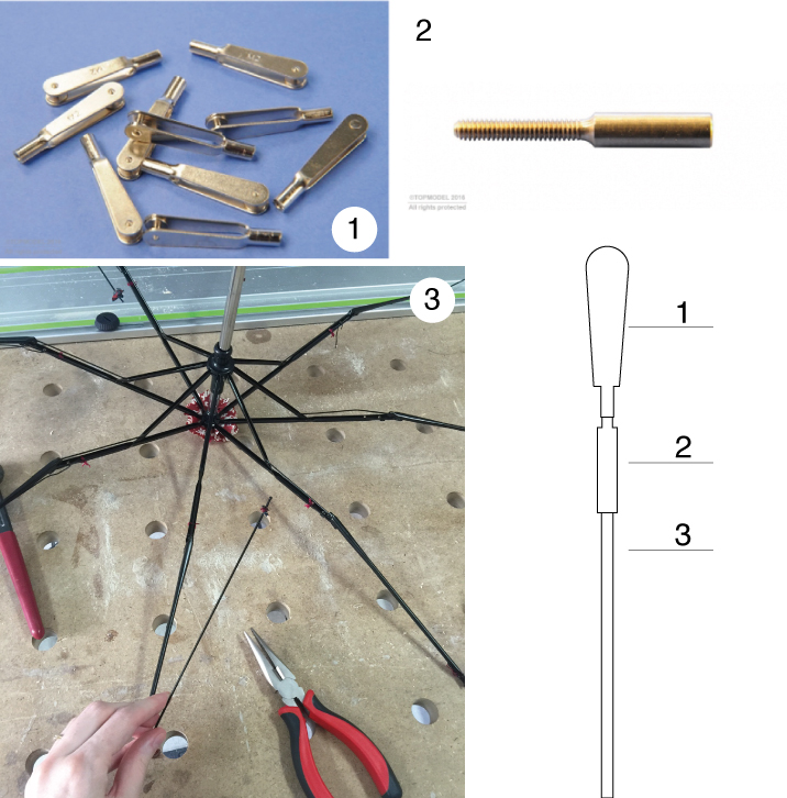
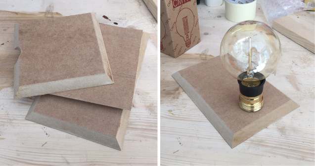
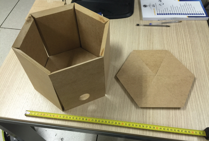
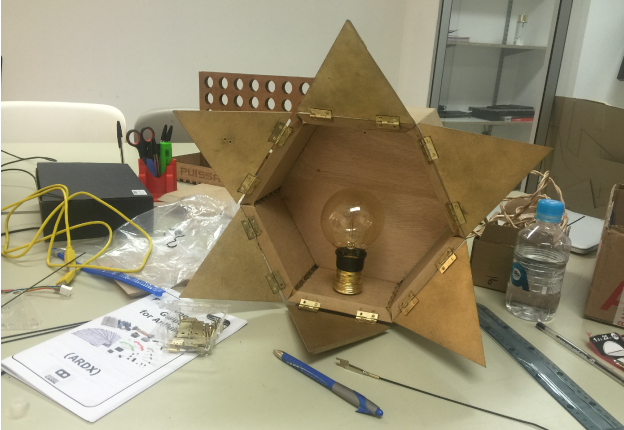
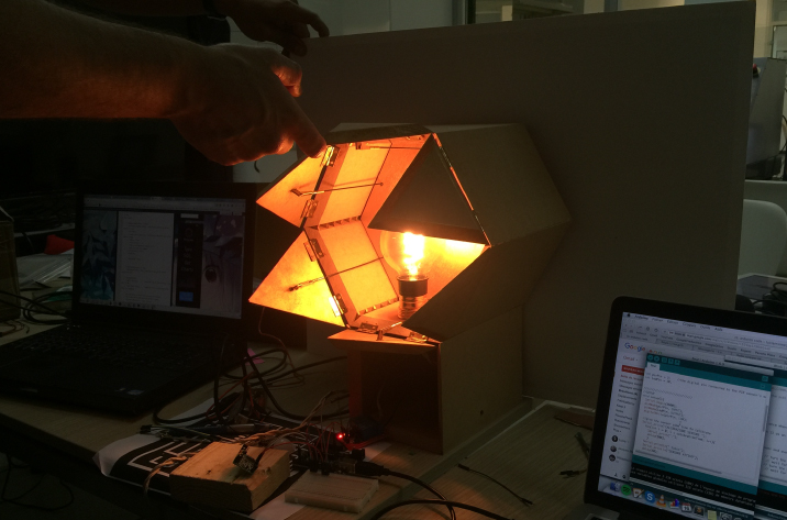
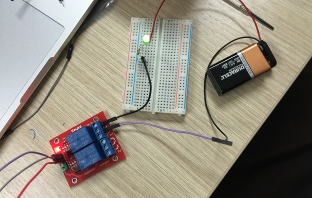
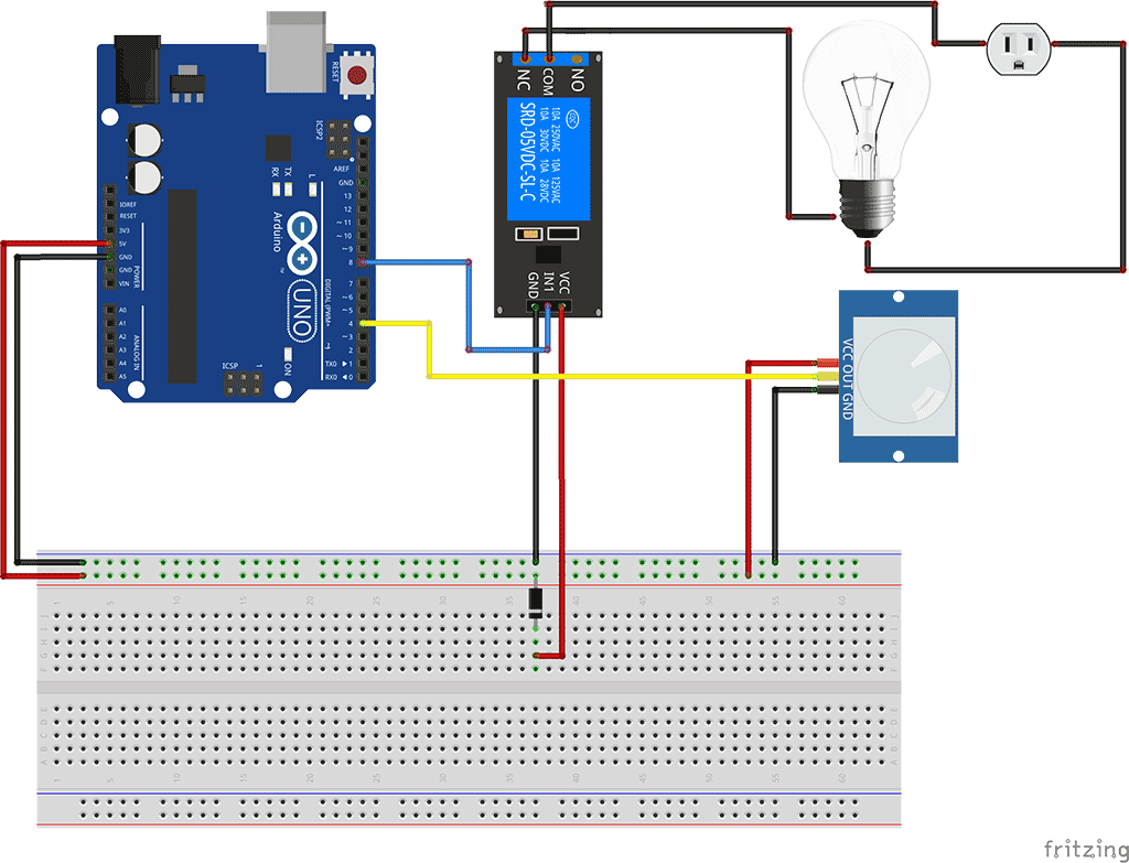
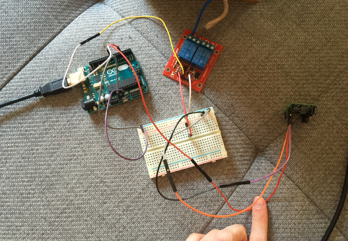
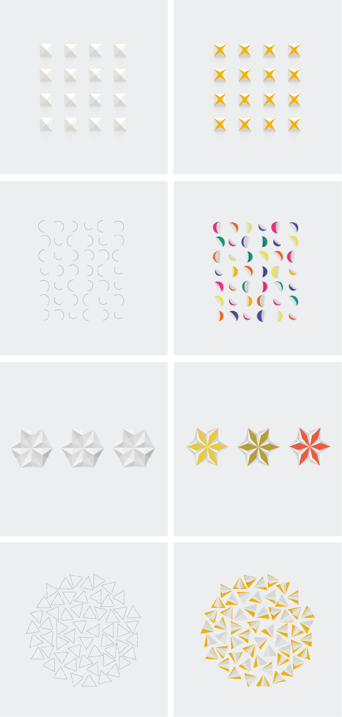
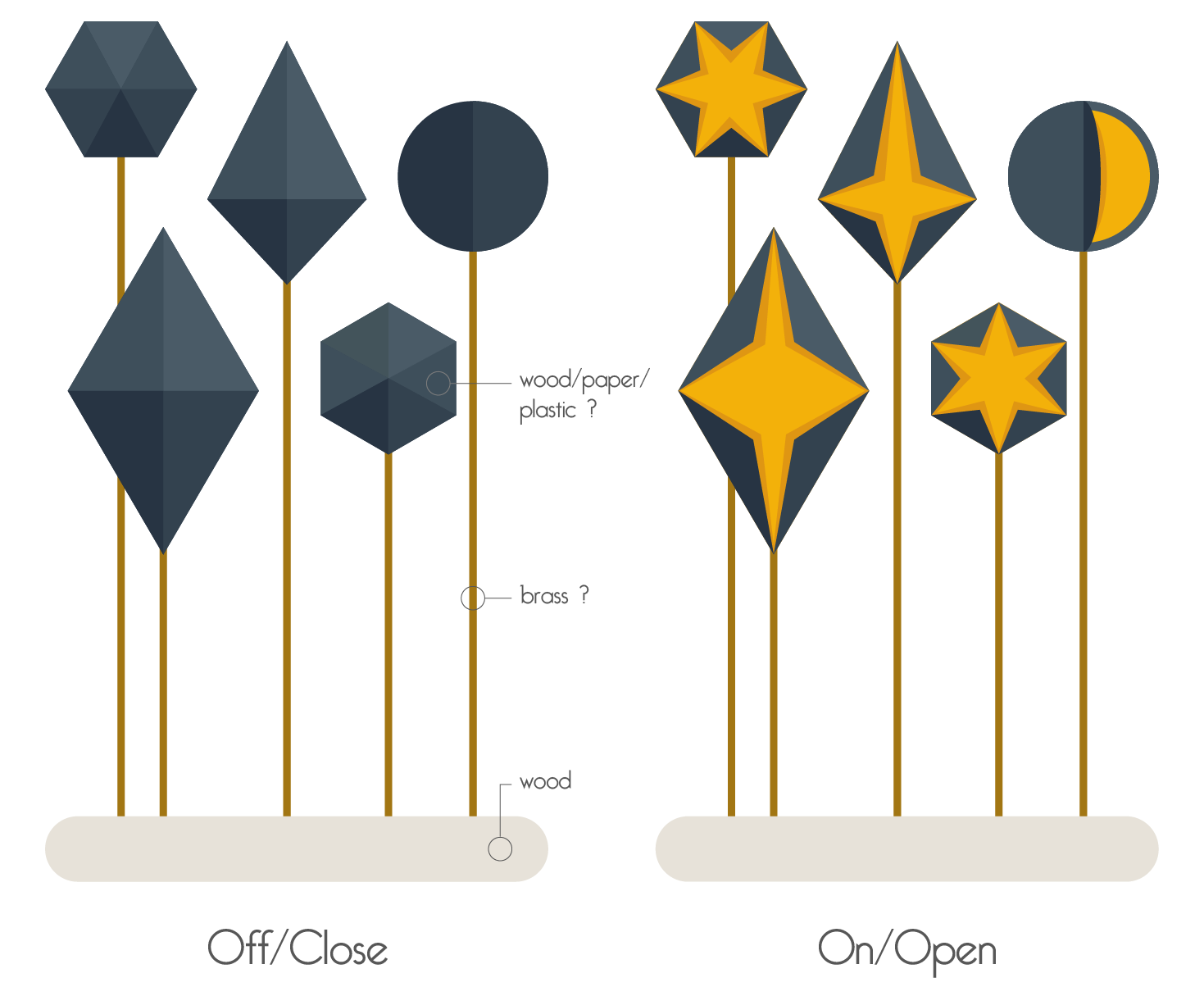
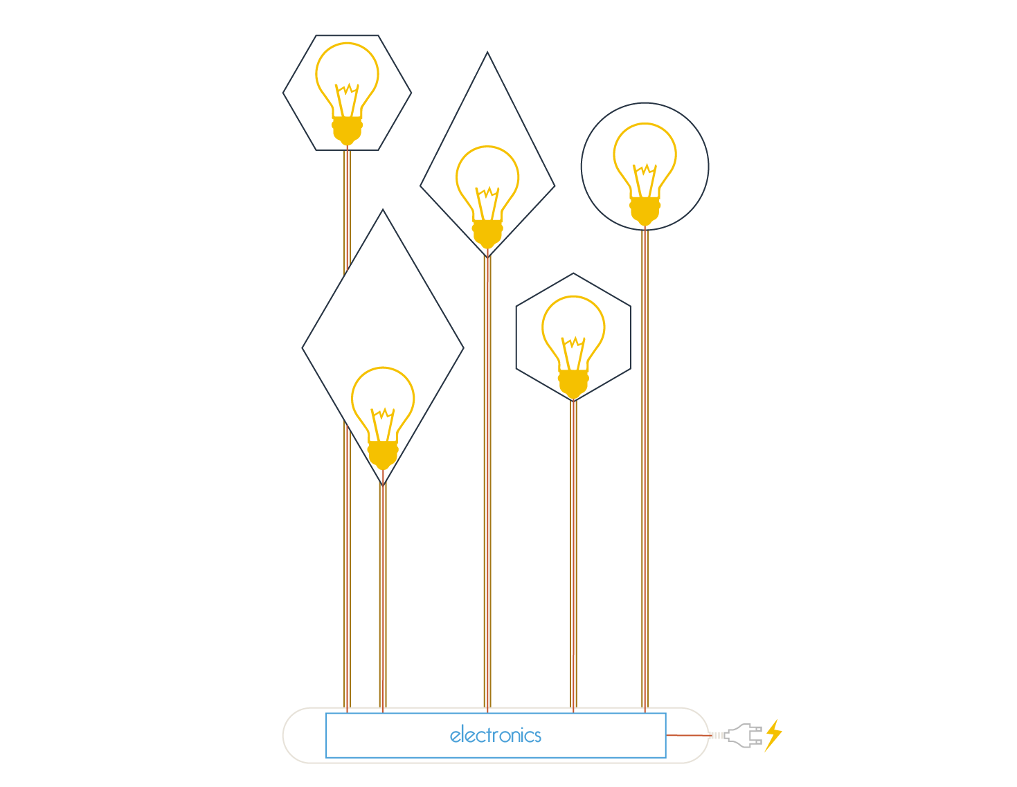
Smart lamp


