Hive Balance with Data Logger
For the reasons stated under the section 'Last minute change of plans', the final project will be the implementation of a hive balance. The weight of a bee hive is a critical variable in determining hive health. A hives weight varies rather significantly during the course of a year depending on the season, the size of the colony (which shrinks dramatically in the overwintering phase) and the how much stores (in the form of honey and beebread) it collects during the year. There may also be times when there are sudden changes in weight such as the honey harvest in late summer or swarming during the spring. In addition, a hive should have a certain weight going into the winter period and not drop below a certain weight during this period or there is a risk of colony starvation and eventual collapse. To this end an reasonably priced solution to measuring and logging hive weight is of great value. Turnkey solutions already exist on the market; however, the price makes them prohibitively expensive for more then just a few hives. This project looks at providing an integrated, single board solution using off the shelf components to build an economical hive balance.
Part I - Electronics
The core of the electronic system will be the ATMega328. The input section is an HX711 24 bit high precision A/D convertor widely used to interface to different load cells. The load cells will be standard 50kg strain sensors in a full bridge configuration. The system will also integrate a RT Clock based on the DS3231. Power will be provided by rechargeable batteries. The output unit will be determined but I am leaning towards a Bluetooth solution.
Part II - Physical Balance
The balance itself will be a modified Nicot plastic hive support. This is a very durable product that has excellent placements for the load cells but requires modification to integrate the load cells and a bar to transmit the data from the foot to the load cell. It might seem like build a base out of wood is a better solution; however, the base of the hive most support lots of weight and be weather and insect resistant to the greatest extend possible. Wood when compared to plastic products does not fulfill these criteria.
Last minute change of plans
There was some discussion in the regional review as to whether or not the lack of mechanical component in the Datalogger project would compromise the acceptability of the project. We put the question to Neil during the Q&A during presentations and he stated that a Datalogger was fine. Phew... However, he also stated that the the STM32 was not the platform to use and recommended instead to use the XMega. This unfortunately creates some timing issues since the XMega is a very different chip then either the AVRMega with which I have experience or the STM32 which I have been studying the last several weeks in the expectation of using it for the final project. This close to the deadline it will not be possible to assimilate the details of a new microcontroller especially the XMega which unfortunately does not have much in the way of the tutorials on the web. For this reason, I modified the project to be a beehive balance which integrates the AVR 328P which is a platform we have used, the HX711 A/D convertor linked to a four cell weighing bridge and an as yet to be decided output device.
All Purpose Data-Logger
In a number of projects with which I am currently involved, the need for a reasonably priced, functional data logger has become more and more pressing. Perusing a number of different catalogs shows what seems to be two basic types of data loggers. The first are very basic one or two variable data loggers which are not expandable, of limited utility and without the sort of interface flexibility that would be required in a more reusable design. The second are 'super-loggers' that basically do about everything you need at the a matching price - definitely not for the aspiring maker with limited funds.
The Arduino world has most of this functionality in some shape or form but to put it all together usually requires numerous shields and extension cards. The results are usually difficult to package and cumbersome to work with especially if the package needs to be robust when exposed to the environments.
This project appeals to me since it uses many of the units covered in the Fab Academy and should be a goal that is reasonable given the experience assimilated during coursework. All the work put into this project can also be used in a number of other projects as the functionalities described above appear frequently in many other projects.
What will it do?
Project will provide input, output and datalogging capabilities to manage different types of information, react to that information and store/forward for later use.
Who's done what beforehand?
This type of device is found in many shapes and forms; however, the costs are frequently elevated, features compartmentalized and programming is restricted. This device combines basic functionality found in different devices and combines them into a single device.
What materials and components will be required?
The device will require the usual electronic components but will use the STM32 Cortex architecture due to its greater extendibility then the AVR series. I looked into the XMega but decided against using it as support on the internet is tepid at best and the functionality is similar to the STM32 but without the ability to scale to larger chips in the Cortex family. The programming paradigm used in register control was also much clearer/cleaner then the XMega system. In addition, tremendous amounts of material exist on the internet for developing on the STM32 in comparison to the XMega including this excellent book written to teach students about using the chip. Its easy to read and explains all the cogent details of using the chip.
Where will they come from
The majority of items will be ordered overseas due to price constraints. Some products will be sourced locally due to difficulty in finding pieces or time constraints on order turnaround.
How much will it cost?
Costs should be reasonable running less then €50 for the prototype. Note that more then €25 is absorbed by the no-solder LQFP48 adapter which facilitates working with such fine-pitch devices. Should the prototype prove successful, a custom made board fabbed professionally will be generated. Note that during a regional review a comment was made concerning the cost of the adapter and how it would be even more expensive to offshore the board. Prices have come down dramatically. EasyEDA is one of many providers of fabbing services (in their case it is directly integrated into the web-based design software) and a small single sided board with a minimum quantity of 5 boards costs approximately 10-15 USD and turn-around is approximately 14 days depending on the efficiency of your local postal service. So, if one integrates the concept of 'opportunity cost' into the real costs of making PCB boards - and most certainly boards with fine pitch SMD components - outsourcing small batch to China is the only economical solution.
What parts and systems will be made?
The board will use a combination of information from all the electronics design units in the FabAcademy notably all the electronics units and the computer-controlled milling (Make Something Big) and/or the composite module.
What processes will be used?
The electronics production tool chain described in previous elements of this web-site will be used. This is generally the EasyEDA web based electronic design tool couplied with CopperCam for WYSIWIG Milling.
What tasks need to be completed?
Principle tasks include - acquiring the necessary skills to program the STM32 Cortex platform for which a number of excellent resources exist on the internet. Next is understanding the basic hardware requirements required to drive the chip on a custom board - a relatively straightforward endeavor. Next is programming the chip. This is the most complicated element and will require some decisions in relation to what technology available on the chip should be used in the project. Due to time constraints, only a very limited amount of programming will be made.
What questions need to be answered?
The most important question is how much functionality can be implemented in the available timeframe. Since we'll be using the spiral project management the following is an approximate list of the
What is the schedule?
The final prototype will hopefully be finished before the end of June though the lost minute changes have thrown a significant wrench in the works. So now the project is moving towards "Death March" status which is unfortunate. So it goes...
How will it be evaluated?
Evaluation will likely be based on whether it satisfies the number of units from the Fab-Academy required for the final project and that the project integrates the information presented during the lectures.
STM32 Data Logger - Some Intial Development Notes
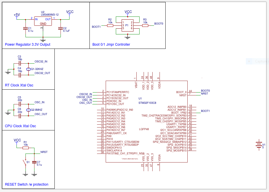
Designing the Core Board Schematic
On the right is the schematic design of the core board made with EasyEda. It represents the core chip and the elements needed to drive the basic functionality of the chip. It is still missing the battery power supply. It turns out to be much more complicated then anticipated to understand to precise requirements of the individual components and the reason for the necessity of additional components over what is require over something like the Fabduino. More on that later...
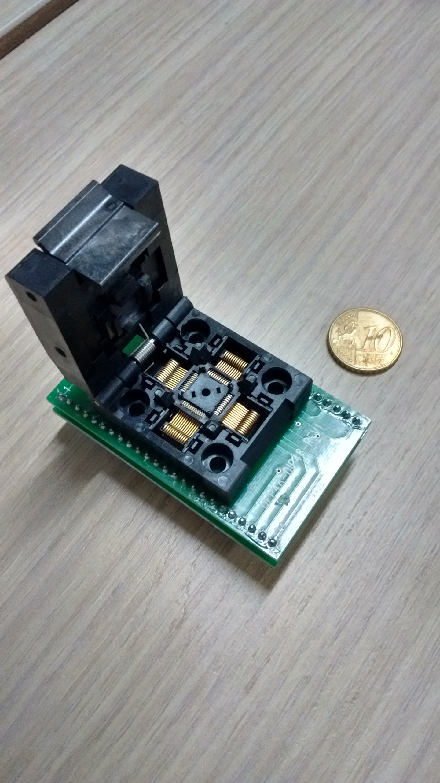
Designing the Core Board Physically
On the left is the LQFP48 adapter socket. This is necessary due to the difficulty of milling the fine pitch of that package.
Milling is an issue not because it is difficult to mill at that pitch but in coordinating the mill with the 1/64" bit and the much finer 0.005" bit. The challenge is in defining the 'high resolution' 0.005" zone and the "low resolution" 1/64" zone and most importantly managing the transition between these two zones. When considering the costs associated with arriving at a milled solution it was much more cost effective to move to the adapter socket and use a PCB Fabrication facility to manage the process for use with a reflow oven we use for small pitch components once the initial prototype was complete.
Prototype milling using the adapter becomes a more feasible goal since it requires skills already acquired during previous modules.
STM32 Programming
STM32 programming is a different beast from the AVR since the programming paradigm is much closer to the AVR Xmega. My motivation for using the Cortex architecture was the similiarity between the Xmega and Cortex programming but the far greater flexibility and functionality of the Cortex architecture. One of the first challanges is the installation of the development environment. I settled on the Eclipse environment since there is an excellent (if not a bit outdated now...) tutorial. Time will tell how well it all works as I am in the process of installing it. Plan B is to use the STM32Cube programming environment.
DELAYED - Experiments in Autonomous Flight
This was my original project idea but I believe it was entirely too ambitous given the timing of the course and other demands on my time. I will definitely come back to it sometime in the future but for the moment it will have to remaine on the to-do list.
My project is about autonomous control systems. Basically, I want to see how far with off-the-shelf hardware, I can keep an airplane in the ski. Now, many of you are thinking that this has already been done and you are correct. However, as I will outline later, the work to date has been based on some rather expensive ‘off-the-shelf’ hardware and my project is to bring costs down to the point where a motivated amateur can build something interesting for less than 1000k. Wow, you say that’s a lot of money! True, but I’ll put costs into perspective in another section.
Background
This idea started when Fablab Connect awarded a replication grant to Lots Amarro for his Flone project. Flone is a quadcopter drone project that can be build for a few hundred dollars (depending on the phones used to pilot the drone) in materials and access to a Fablab for machines, tools and advice. I worked on ‘replicating’ the Flone in Fablab Ajaccio and was amazed by the functionality of the flight controller board (then a MultiWii board). Immediately thinking of the possibilities, the idea of building a solar powered glider came to mind. A few google sessions later and it seemed (and still does) that no one had tried to put all the pieces together into an ‘affordable’ package. It sounded like an interesting project to see what was possible given the ever-dropping costs of the hardware involved except for one item – more on that later.
Projet Planning
There is a lot technology in this project and it would be impossible to develop all of it in the time frame given in the project. This going to managed in the spiral style as mentioned in Niel’s first lecture to be sure something actually flys. (NB - I haven't decided for which specific parts of the project I will be using off-the-shelf componenets and where I will be building them myself. There are also some areas where it would be interesting to make modifications where possible but without jeopordzing the final project. One are in particular is building wings from scratch and skinning with carbon-fiber. This would great to do in the composites and 3D design modules but if it ultimately proves too onerous, the plane can be flown with the original wings.
One particularly interesting element in this project concerns the laws surrounding autonomous flight. This is still a grey area in a great many countries especially if flying UAVs for non-commercial uses. Note specifically, that the planes being developed can reach altitudes where commercial and private pilots operate creating potentially dangerous collision risks. The abilty to test the plane may be complicated as living on a small island requires some consideration for protecting life and property. One thing that is not part of the this project but merits further investigation is the development of lightweight and certified ADS-B transponder.
Functionality
The functionality of the project is going to managed in the spiral style as mentioned in Niel’s first lecture. In order to keep costs as low as possible, off-the-shelf (OTS) components will be used where possible with customization where necessary or when part of the Fablab curriculum presents an opportunity to work on some element of the design.
Here are the basic elements for complete functionality:
- Remote-controlled (RC) glider with electric motor
- Auto-pilot system with GPS
- Telemetry system for data management and communication
- Software to manage power requirements and guidance systems
- Power Management system including solar cells
- First-person-view (FPV) video system
Airframe
The airframe is relatively inexpensive foam glider. This model was chosen over more expensive models for the simple reason that crashing one will cost less! We'll also be looking into some possibles to modify the glider in different ways which is also more cost-effective on something that isn't already a work of art. Finally, this particular model has a strong community on the internet making it easier to debug some of the hardware shortcomings.
Auto-pilot
The autopilot will likely be 'Libre-pilot' which is the rebirth of the Openpilot project. This is not yet certain since I've not had the opportunity to review all the offerings on the market and each is actually quite complex. I will try to write a seperate post on this subject when time permits. The most important criteria is that the project be open-source.
Telemetry
Now here things start getting very interesting. There is a lot to be investigated under the term 'telemetry' in terms of functionality and the project will look at what is available OTS and what opportunities exist to hack different systems. Most manufactueres are using a sort of databus that can communicate through the transeiver back to the ground station. The quesiton is how difficult is to 'plug/hack' into the databus with custom made equipement. We'll be coming back to this subject when the modules for sensors start.
Flight Management
Flight management is different from telemetry as the former is just data while the latter integrates a certain level of decision logic. The idea or this project was inspired by a the disseration of Daniel Edwards on autonomous soaring. Other projects also exist but I've not had the time or access to a university library to do a full search on the current literature. The flight manager is what controls the airplane during flight in terms of waypoints and thermal searches. It interfaces with - or is sometimes part of - the telemetry system since the telemetry data is what the flight manager processes.
Power Management
Power management is an area which will be variable in terms of its scope. Initially, I had given some consideration to adding solar panels to the wings but background research into ultra-light flexible mylar cells showed it unlikely to be in the budget (both monetary and temporal) of this project. However, at the list it will be interesting to see how it might be possible to manage energy consumption in flight depending on the phase of flight and sensor packs being used.
FPV
First-person-view (FPV) is on the nice-to-have list. It's a technology that has come to a price/performance level that makes it possible to integrate a real-time camera of very high quality into a headset for only several hundred dollars. While it isn't necessary for the project, if the opportunity and materials arrive, it would be very 'cool' to have this on board.
More detail will be given on each of these elements over the course of the Fab Academy. Some of the functionality may or may not be achievable in the time provided by the duration of the course which is why it may be necessary to drop some functionality in the final project.
It should be said that some elements on the list - most notably the solar power panels - will not be available in this iteration of the project. Ultra light-weight mylar panels exists but are still in very early in the development phase. This means that it will not be possible to procure the panels at a reasonable size.
Costs
The costs for such a project really depend on the budget in this case the budget can best be defined as ‘very tight’. The glider will be OTS from Hobby King and will cost about EUR 150 (and what is up with those shipping rates?!). The Autopilot will cost between 50 and 250 depending on the hardware solution chosen. The autopilot software is all open source so is free. Telemetry will be combined with a telemetry transceiver which costs between EUR 100 and 300. FPV equipment is upwards of EUR 300 depending on the configuration. The power-management system will be designed from scratch and depends on the parts used but should be less then EUR 50. The custom control software will be a question of time. The only piece of the project that seems prohibitively expensive are the ultra-light thin-film solar cells. I’ve not been able to track down a source for these though they exist and are used in similar projects. While ancillary to the project, the cost of the ground station transiever is not
Prior Art/Bibliography
Dan Edward's Dissertation on Autonomous Soaring
Flone Project Homepage
http://www.theguardian.com/technology/2015/aug/12/google-testing-drones-us-airspace-nasa-deal-private-land
http://www.theguardian.com/technology/2016/jan/29/project-skybender-google-drone-tests-internet-spaceport-virgin-galactic?dom=prime&src=syn
More coming soon....