Computer Aided Design
This module explores the basic (and not so basic) elements of computer aided design. My personal experience has been with Autocad and Sketchup for architectural and construcion modelling. I was recently introduced to Solidworks by our FA instructore and was very impressed. For this module, I will be working on increasing my knowledge of Inkscape and Solidworks.
For this module, I investigated how to design a wing. I was pleasently surprised at the amount of information already available on the internet especially internet. Solidworks is the application I was most interested in since it was designed to build assemblies. The steps are relatively straightforward if we have a flat wing. Before anyone things I was able to do all this, let me direct to this Youtube video where someone has already taken the trouble to describe the process:
Here are the general steps as outlined in the previous video and which I will attempt to repeat.
- Choose airfoil profile
- Convert tabular design data into import file
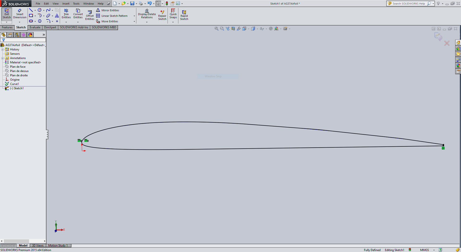
- Import the 2D description into sSlidworks
- Use Solidworks to 'extrude' the wing
- Work on the details

Choose the airfoil profile
Not being an aeronautical engineer, I'm not going to try and 'create' my own wing profile. Luckily, that's not necessary since there are many profiles available and one of the most well known is NACA. The database itself - well, one of the repositories - is managed by the University of Illinois Applied Aerodynamics Group. Another site is Airfoil Tools which provides a large database of design from both the real and model airfoil design community. For this example, I have chosen the AG37 airfoil which some consider very good for long range flights. At the right is screenshot of the data for that airfoil and the coordinates are available in various formats on the screen.
Download data, convert to solidworks format and import
Airfoil data is provided in two column XY data which is not what Solidworks takes so we need to convert the two column data into three column data by adding an array of zero Z coordinates. This can be done in any spreadsheet. Note the data supplied is normalized to mm units and needs to be altered to accomadate the chord of the desired cross-section. In this example the chord was set to 200mm.
Importing the data is actually a matter of opening the Features->Curves Through XYZ Points and cutting and pasting the data. Depending on the regional settings, the decimal place designator may need to be converted to a dot from a comma. Once imported, the line needs to be converted to an entity so that it can be treated as a piece of Solidworks geometry. Once the entity conversion is complete, it is likely necessary to close the trailing edge of the wing so it becomes a closed space.

Use Solidworks to 'extrude' and detail the wings
Building the wing requires extruding the profile to the length desired. It is also possible at this point to define a material so the mass of the wing be calculated. Once the mass is available, there are some functions in SW that permit building a surface or a volume instead of a having a solid wing. This is beneficial as first it reduces the weight and secondly reflects the requirement that some internal volume be available to run servos for the control surfaces.
Unfortunately, I was not able to get the "Shell" functionality to work properly so I used a solid wing. This is not significant in this excerise. The endtips are built using the 'Dome' functionality - be sure to uncheck the "Continous dome" checkbox to enable a full dome. On the left is a screen shot of the wing section. It is now possible to some airflow simulations but I decided against this since I'm not able to really understand the results so we'll save that for another day.

Testing some other software.
We looked at some other 3d software. The most interesting one was Rhinercos/Grasshopper. Personnally, I found Rhino to be similar to Unity in the interface and the manner that you interact with screens. While impressive in the scope of functionality, the applicability to "real-world" uses is somewhat limited compared to a product like Solidworks. However, I say that not having reviewed all the capabilities and there were some uses in data visualization that could prove interesting on closer examinations.
Sketchup is a tool that I have used on many occasions for architectural modelling. The product is very intuitive and you can get excellent results quite quickly. If I needed to do a quick design of a space then Sketchup would still be my first tool-of-choice even compared to Solidworks. Plus if one doesn't have access to a Fablab license, Sketchup remains a much better value.
To-do
Continuing to work through the videos of Mighty Wings is an excellent guide to physical modelling.
Bibliography
The Youtube channel of "Mighty Wings" is an excellent source of informatin for everything that is airframe design of airfoils and airframes.