Brief description of my final project ( week 01 )
Geometry, Design and Fabrication are subjects quite familiar for me. In the other hand I am not used to electronic devices, besides I only have basic knowledge about programming. So I chose my project from a global point of view. I am going to try learning to operate electronics devices and programme them but from the particular area of the geometry.
I am very interested about responsive architecture. Perhaps thinking on mobile elements related with building construction is a hard challenge. Mobile, foldable, transportable architecture are recurring subjects. Even would be considerated as an heritage from vernacular architecture.

Nowadays we can see sophisticated constructions focused in this kind of approaching but alternative researching ways related with the material behavior are overcoming mechanic devices.

I am going to start from a kind of foldable piece, like a simple origami exercise and I will try to embbed inside such a mechanical system that could be controlled by a determinate external impulse.
This sound quite simple but I am thinking about facades and the possibility to be able to generate a self-controlled system to operate the open-close process in order to measure the energetic flow through the glazing system.
In fact there are some examples of this kind of systems. Would not be an absolute original idea but I hope this process allow me to understand the global process of embedding intelligence inside architectural things.


My Final Project is focused on the design of a Sketch of modular photosensitive system facade.
Main Issues that I have pointed were:
1. MODULAR development of a flexible system that can be adaptated on any kind of surface.
2. Researching on physical systems CONTROLLED BY GRAPHICAL INTERFACES.
Both of these approaches are related with my work as architect.
First model had more geometrical complexity although it didn’t offer more deployability because the opening area was lower, so I decided to work on a simple deployable model.
An important point I focused was the Modularity, I have tried to work with a single module but inside a more complex structure.
The Mechanical system would be the sticking point. I wanted to get a transparent module where the structure vanishes as far as possible.

Some conceptual sketches about the posible answer to the deployable system using rotational movement. The simplest solution would rotate 90 degrees using only one servo that would be arranged along the Z-axis.
Electronics:
I have been working with micro controlled boards using photo resistors, phototransistors and motors, both servos and stepper motors, but in the final project I work with a Fabduino Board/ satshakit because the next reasons:
1. is the simplest way to communicate with Grasshopper using Firefly.
2. it is possible to control many modules with a single board.
In the week 11 I decided to reproduce the Satshakit board, Fabduino designed by Danielle Ingrassia in order to get a board that allow me the communication with the Grasshopper environment using Firefly. As I said, I usually work on Grasshopper and my main objective is to produce a physical model that could be controlled from a graphical interface as well as could be monitorized data from the physical model.
So I would be able to close the circle through this kind of matter related with bits and atoms.

Component list waiting to be stuffed.

First trial, First error! When I was trying to connect the board using FTDI cable, the computer drive out the USB because it was demanding too high level of power supply. A short-circuit should have done in some place. Perhaps,the problem could be related with some kind of cutting down edges of the wires because I have reviewed all the components and the connections one by one and I didn´t find any kind of error.

Second trial, it seems much better! but I was afraid about it wouldn´t work...

Programming the board using Arduino. Daniel´s work is absolutely useful and well documented.

The board works properly!! Using Arduino IDE, selecting Arduino UNO as board, Arduino as ISP and the correct serial port where the satshakit is connected, procced to BURN BOOTLOADER.

Connection scheme using FabISP.

PIN location on my FabISP, Zaerc´s FabTiny ISP.

USBtiny acknowledged at USB port and FTDI cable as COM8.

Burnloading the satshakit using USBtiny.
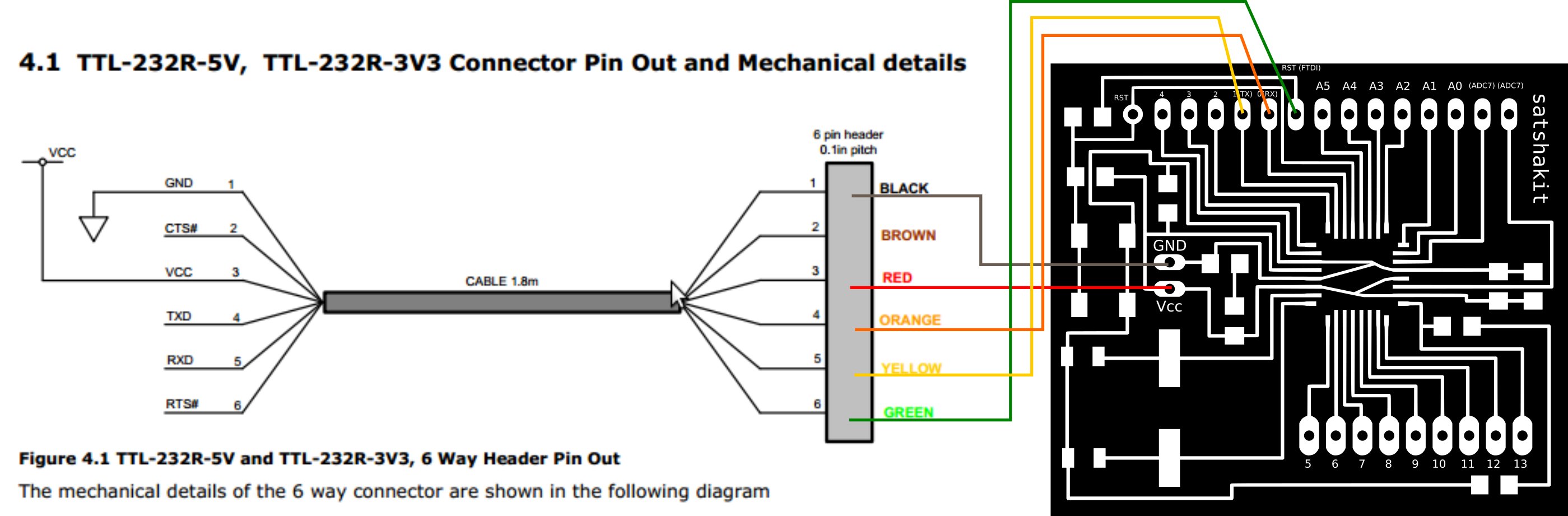
Schematic arrangement of the satshakit connections using FTDI cable.
In the week 13, I have been thinking or rather I should say rethinking about my final project and I have decided to introduce a new sensor in order to control and mesure the function of the physical device I was developing.
I was tinking with hall-effect sensors but The result was not sucessfull.
More or less the scheme of the whole project would be some like the sketch bellow.

Programming
Input devices: Light level sensor. Photoresistor Input in Fabduino Data Lecture in Firefly
Output devices: Mechanic rotational sytem. Servo-motor.
The function of each module works in this way:
A light sensor send an individual impulse to the MC: in this case a photoresistor write to any Analog Pin in Fabduino board.
Numerical values are translated into movement: So the necessary rotational movement, only 90 dregree, is controlled directly using the related output pin. In this case it is not necessary but could be controlled by some kind of function.
Both questions graphical interface and physical devices are programmed using the same Grasshopper code.


Physical model
Input devices: Light level sensor. Photoresistor Input in Fabduino Data Lecture in Firefly
Output devices: Mechanic rotational sytem. Servo-motor.

Final Parametric model of the module showing the frame and the deployable glazing system.

The dimensions of the module advise to use laser cutting 5 mm. MDF board.
Epilog Engraver 50% power/50% speed

Mounted frames of the modular system.

Printed pieces on Prusa i3 using PLA.
210º hotend/70º bed Temperature.


Assembling the frame. Different details. One of the sticking points was the piece that conect the disc and the axis. The solution passed trough the use of a reinforced pipe avoiding the bend of the wire.


Finished modules showing the different opening of the deployable screens related with the ligth amount.
Improvement and further development:
1. Translation from square to quadrilateral modules.
2. Measuring of physical model in order to correct the graphical model.
I have been trying to get some kind of sensor system in order to measure the opening of the physical model and so be able to translate this measurement to the graphic interface. By now is one of the next points to beat.
3. Improve the engine:
I choose servomotors because the size and the weight of the module seem them more appropriate but as a later research I am thinking on fabricate a bigger module so more powerful engines or motors should be neede. I think that stepper motors could work fine.
3. Improve the ligth sensor system:
Sensors that offer more reliability, I have been testing the photoresistors using a luxometer and the data obtained are not fullfilling.

After my final presentation Neil recommended to me that should be better to package all the electronic stuff in order to improve the final prototype. It seemed a good suggestion.
Really the module will be a part of a major system and the final connections will depend on the arrangement of the whole model, moreover if many modules would be connected using only a single board. But I think that it is worthwhile to spend some time improving my prototype.


I just have designed a box in order to put in the main board and the electrical connections. It has been printed using PLA.
Really it looking so much better!


