Mechanical Design & Machine Design

FabLab Leon Supernode McNulty Wire cutting Machine!
This work actualy is assigned for two weeks and it has been really a big assignment. Here I am going to do a brief review about these two weeks of amazing work.
First I started to Review the huge documentation about MTM when I met my partners we Discuss about the machine we want to do.
Among other ones We specially focused on the machine that was done at Fablab Puebla on 2015
Positive points we have taken into account in order to select this work
1. It is possible to cut warped surfaces.
2. It seems a strong enough machine.
3. Well documented.
4. Quite simple but really useful machine.
Main Issues to improve ( almost to try )
1. Design a hot wire support which cutting strength could be regulated/modified easily
2. Design a stronger frame
3. Portability
4. Foldability
5. Finish in general
How we faced the issues
There were two special questions we decided to deal.
Reinforcement of the structural frame.
It was a minor problem. The frame was easily strengthen adding a horizontal beam, so the frame obtained is really strong and quite static. This modification changes the original structural concept from two cantilever beams to a rigid frame built with two pillars and one horizontal beam.
Besides the horizontal beam could be used to get inside the electronically control of the machine and the place to put it on the power source.
Modularity of the machine was another address and in this way the concept of the design focused on using equal dimension modules. So the same prism volume is used to solve the Z-axis ( pillars ) the horizontal one and the beam as well.
The fixing system of the wire was a question a bit more difficult
I was focused on the design and the construction of the structure was my main objective but I was doing some work on design and construct the wire system support.
In order to improve the structural behavior of the machine we decided to use 3 mm MDF board instead of cardboard. Here the main problem was the maximum dimension of the laser cutting machine available which allowed only a dimension cutting surface of 600.300 mm.
I reviewed the original Puebla design files.
Personal Work
To be honest, is difficult to say which has been the part each one has done. I think that the most positive question about this assignment would be the working proccess by itself and the perfect connection between us. Thus each one has collaborated almost in all the tasks. So everyone has had a direct or indirect intervention in the phases so in this way the learning process has been amazing.
Anyway I have been mainly focused on two main points:
1. Parametrical design/redesign of the mechanical parts.
2. Programming a graphical interface.
Beginning on the approaches of the improvements we try to introduce into the original design. Once we decided what the objective was, I focused on the MDF structure. Drawing, cutting and fitting all the pieces.
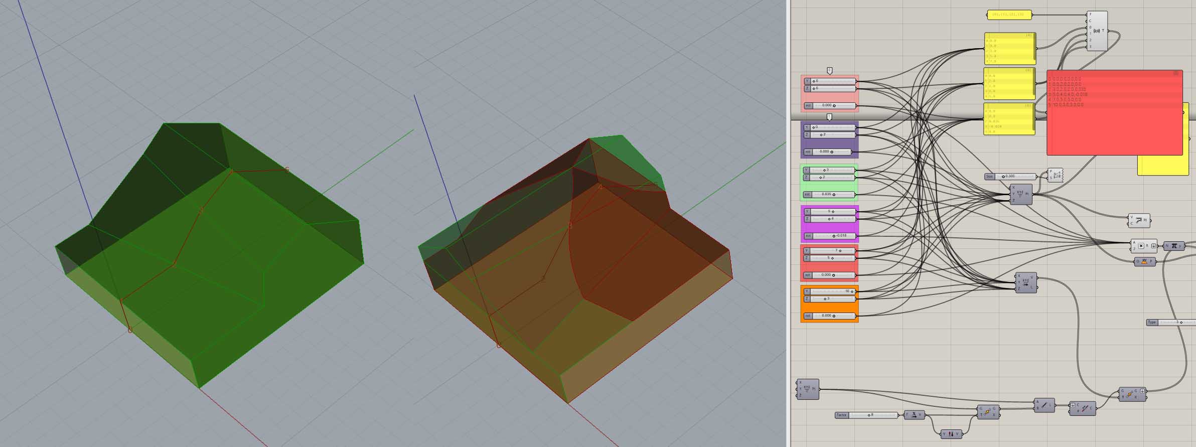
I have used a parametric model in order to get a better vision about the whole model and its operating.
Besides I have arranged the parametric model to trace the sketch of the surface that the machine cuts, in this way we can relate the CAD model and the operating computing system of the machine through such a graphic interface.
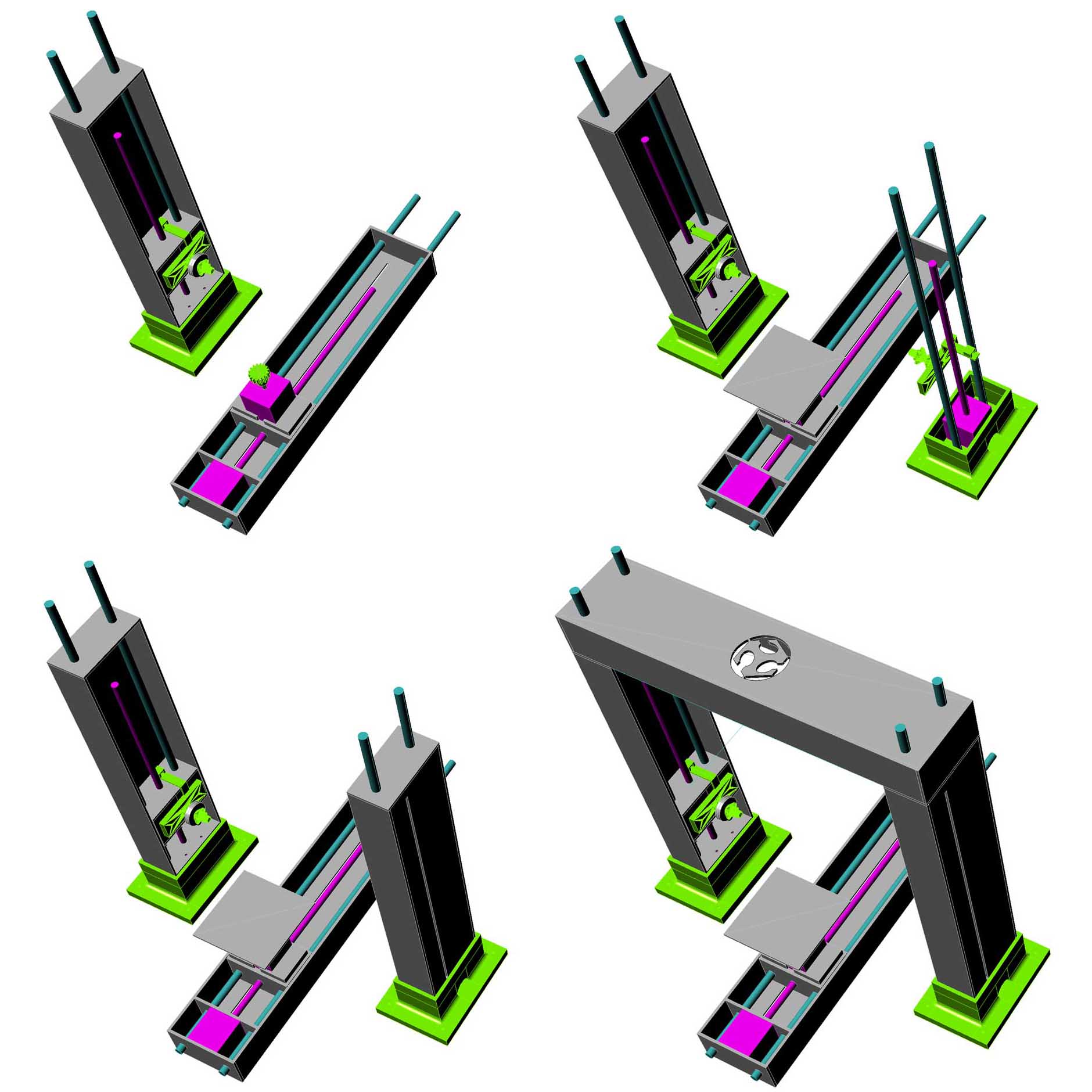
Parametric model showing the different phases of the assembly.
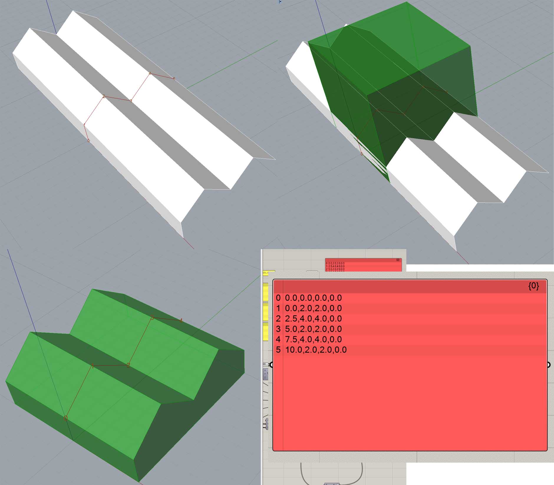
The four numerical values that define the movement of each stepper motor can be translated on the movement of a straight line in the space. Hece we can arrange a graphical interface using Grasshopper in order to draw the final piece that the machine will cut. Even it is possible to combine various processes overlaping two or more section progresses.