Electronics Design
Redesign the Board
The assignment for this week is focused on reproducing the HelloWorld PCB with a couple of extended features. These are a LED and a push button. I reviewed some tutorials about that question and after that it seems pretty simple if you compare with the first electronic assignment which was an absolute nightmare for me.
So I tried to refresh my rusty knowledge about electricity. Actually if you want to add some new features or components on the board these ones have to be integrated into several circuits. In this way I calculated the resistor values in order to ensure an appropriate working of the LED and the microcontroller.
I installed Eagle and the necessary libraries as well. Eagle is intuitive enough CAD software and redesign the scheme did suppose no problem. The electrical layout you obtain from the scheme turns out to be a bit a difficult but not much. You have to replace some traces and accommodate the features trying to arrange them in the better way you can. Undoubtedly, parametric processes as that Eagle uses represent a qualitative leap into any kind of process.
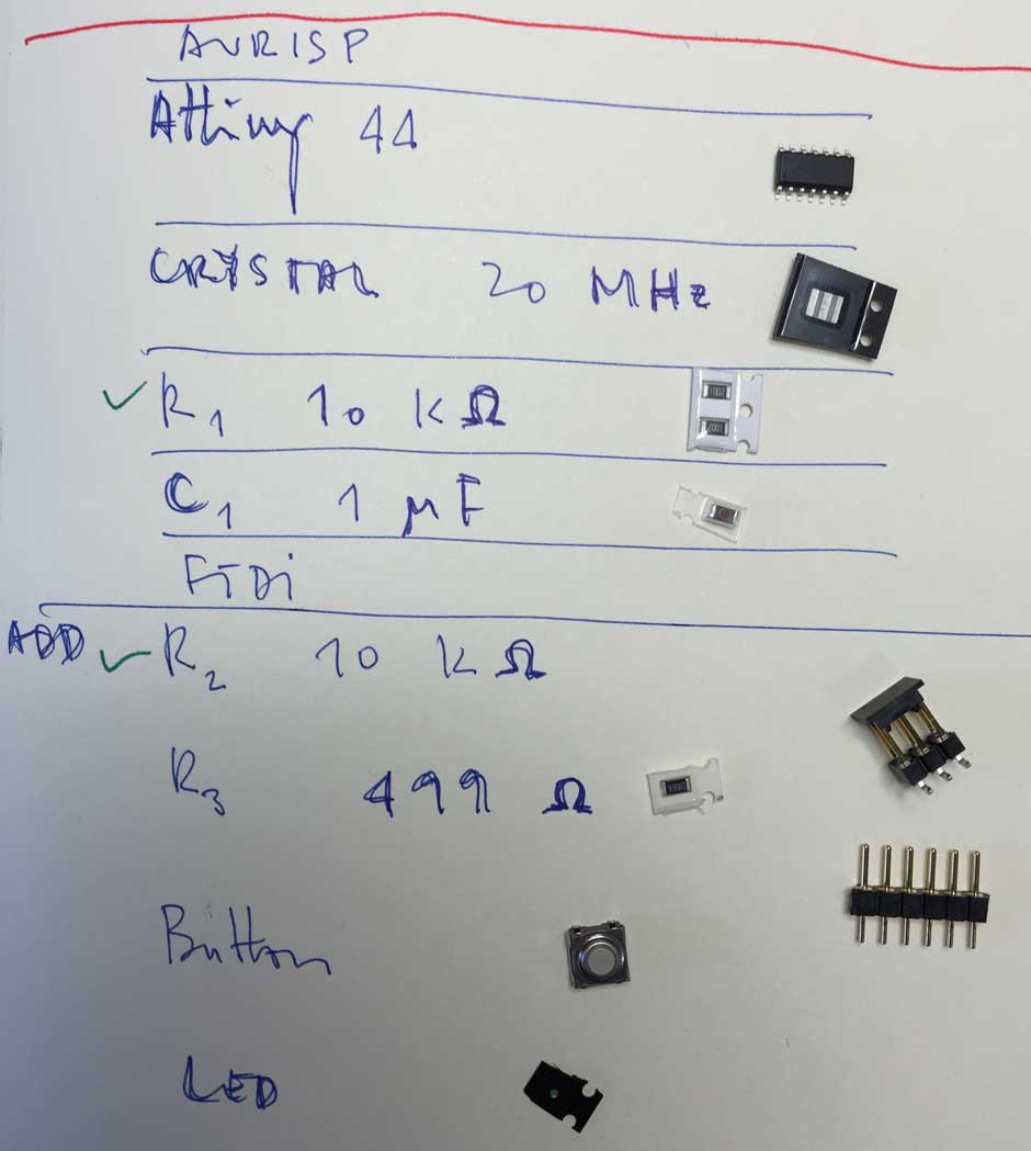
Original components in the HelloWorld PCB:
- resonator 20 MHz > 2 is the GND (ground) and fix the direction should be down
- capacitator > 1µF
- Resistor > 100KΩ
- ATTINY 44-SSU > the circle marks the orientation and VCC should be top left
Components that have to be added:
- LED (+ resistor) > in fact, is a diode, so the end marked with a green line is the negative pole, which must be connected to ground
- Resistor > 499Ω
- Button > 6mm_SWITCH OMRON SWITCH
- Resistor > 100KΩ
Also, it is necessary to provide:
- AVR ISP > 2X03
- FTDI-S > 1X06SMD
Chosen a red LED from DigiKey (160-1447-2-ND) with electrical parameters 2 V and 20 mA the resistor value has to be calculated in order to ensure that the LED works properly if the resistor value would be lower the LED will be burnt. The correct value was 150 Ω (R=V/I) but I took a 499 ohm resistance ( I have no low resistance device, but it don’t mind ) . As a result the luminosity of the LED will be lower than it could be reached, its value would be calculated at a maximum of 30% of luminosity.
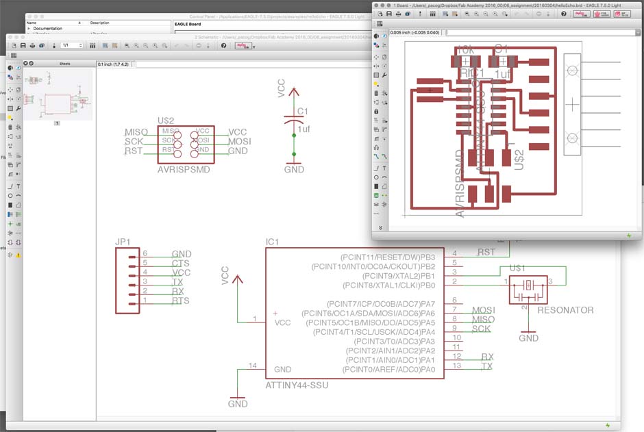
Once you get the original archives, they shoulkd be checked into Eagle.
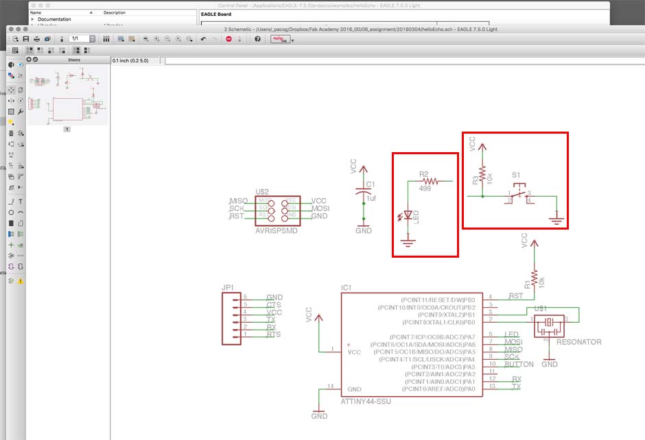
Introduction of the new circuits. The circuits have to be properly labeled in order to connect all the stuff. In the image above Ground connection in the circuits have to be labeled with GND, so all of the circuits will be plug in the same point. The opposite end of these new circuits have to be labeled with the microcontroler exit you chose as well.
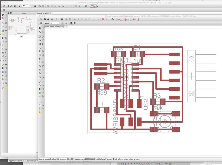
Once the circuits are correctly arranged into the scheme you have to resize and redesign the board on the board view.
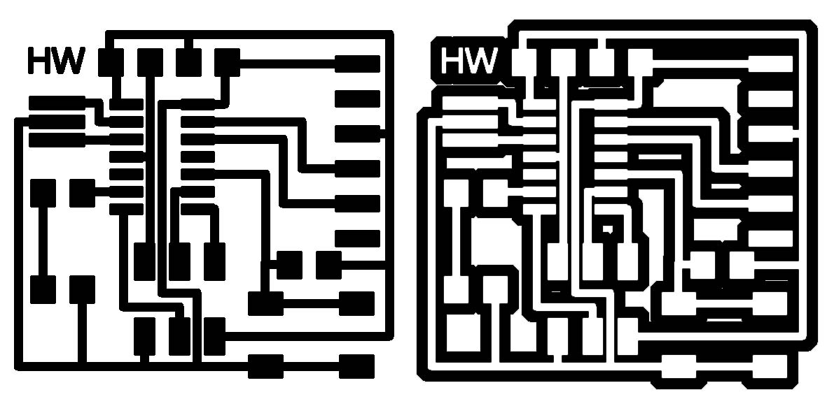
Export the finished traces desing of the board and adjust the correct image file in order to mill only the necessary routes.
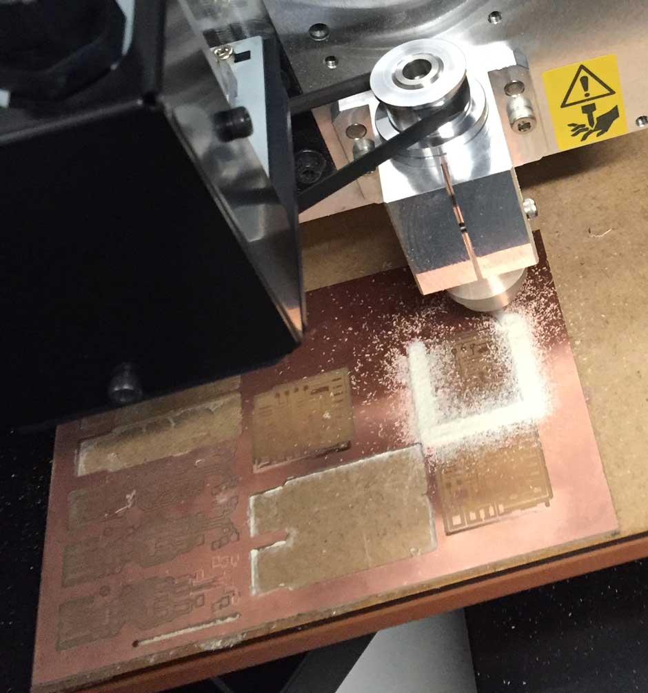
Some problems again during the milling phase. I had to try it during three times until I got a fulfilling result. First the board did not mill correctly on the lower part of the plate ( bellow-rigth ). I thought that probably the original plate was slightly bent along the border, so I repeat the milling proccess above and took in acount that the recurrence of the same problem ( center ).
I could not detect the problem and finally I decided to mill the board separately in two fases, thus I split the image file in two halves and first the lower half and secondly the other one. In both cases I got a correct work, I am a bit lost on which it is the problem.
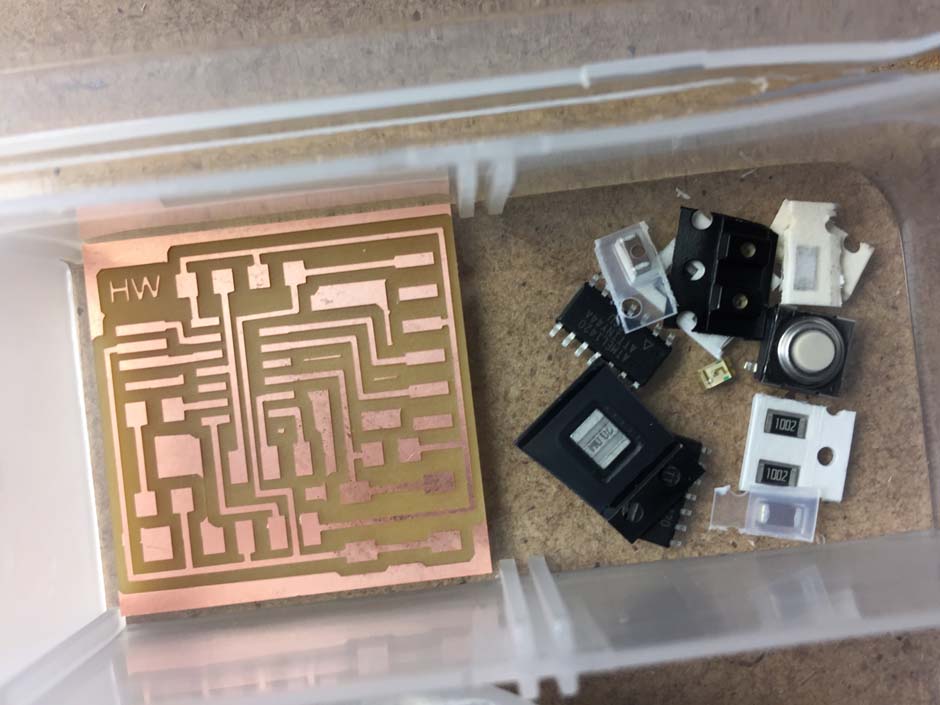
Making ready the board and soldering all the stuff on it was a similar work that this one I did two weeks ago.
For me it was a funny time.
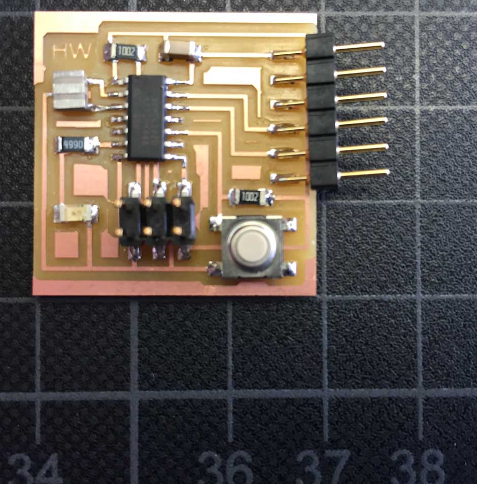
Finally, the modified Hello World Board! Waiting the next step, I hope to be able to do it again as well!