Exercise 11: Input Devices
Input device with Ultrasonic sensor
For this week I am going to make an input board with an ultrasonic sensor because I want to use the ultrasonic sensor for my final project. Before I made my board I did some research on ultrasonic sensors. Ultrasonic sensors work by having a speaker that makes an ultrasonic sound wave and then times the time it takes for the wave to reflect back to a sensor. I did some research on ultrasonic sensors and was originally looking at the Maxbotix ultrasonic sensor from Sparkfun click here . These seem like really nice sensors and they have an integrated speaker and receiver and so they are relatively small but at around $30 they are also really expensive. By comparison the HC-SR04 ( click here ) is just a few dollars depending on the deal Amazon is running at any given time. The other advantage is the HC-SR04 is that although Sparkfun and Maxbotix has good documentation on their sensors, the entire internet is awash with documentation on the HR-SC04. One manufacturer has a good manual on the HR-SC-O4 click here .
Summary of HC-SR04 Specifications
To summarize some of the most interesting information detailed in the manual:
1. Requires at least 4.5V to function. This is good because that means it will work with 3 AA batteries, which is what I plan to use for my final project.
2. Functions by producing a 10 us pulse 5V pulse to the trig pin which causes 8 40kHz pulses. If the receiver detects a pulse it will set the echo pin to high (5v) with a pulse that corresponds to the delay which then calculates the distance as Distance in centimeters = delay Time / 58 or Distance in inches = delay Time / 148
3. The range of the sensor is 400cm/13ft and the resolution is 0.3cm and it detects reflected ultrasonic burst at up to 30 degree angle.
Making the board
I started by drawing out an ultrasonic board in Eagle Cad based on Neil’s design. I designed two boards, one that was identical to Neil’s board and one that I changed the design slightly so that it had a side by side jumper.
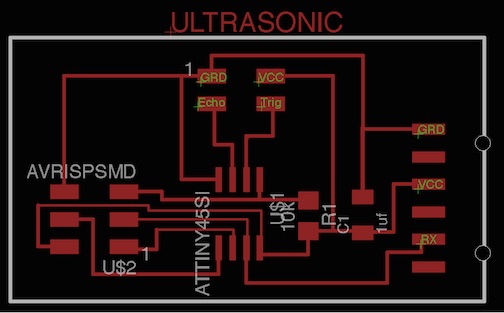
The ultrasonic sch file click here.
The ultrasonic brd file click here.
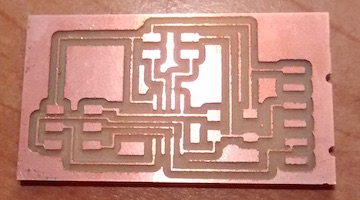
I then milled the board using the Othermill
. 
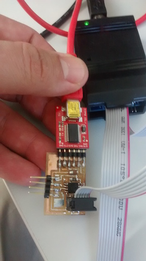
I then soldered on the components to the board. It came out really well I was very confident it would program successfully.

After soldering on the components I then burned a boot loader to the board using a USBtiny with the internal clock set to 8mhz. (see Week 8 embedded programing). I also made a board that I cut directly my Lab partner cut directly off of Neil’s design using the FAB modules. The picture shows a second version of the ultrasonic board I made using Neil's design, but the hook up for the FTDI cable and the programmer are the same for my board. In terms of process I tried everything that I did with my board also with Neil's board with essentially the same result.
Programing the Board
I am writing this documentation long after I did this lesson because at the time of this lesson my understanding of microcontrollers and programing them was very sketchy. The first thing I did not understand was how Arduino are different/same as the ATTINY microcontrollers and how any of the ATtinys are different from each other. This caused me confusion because I did not know how to go about finding the correct code for my ultrasonic board, which was an issue due the fact I could not use Neil’s C code as no one in the lab at the time knew how to load C code onto the microcontrollers. Instead I tried to find Arduino code that would work on the ATTINY45, I could only find code for ATtiny85’s. At the time I did not understand that the 45 and 85 processor are basically the same chip but just with different memory capacities. The other thing I came to understand about ATtiny processor for microcontrollers was that the only other important difference between the 45 and the 44 was that the later had more pins. For a good overview of this and pin layouts for ATtiny processors (click here). So what I finally came to understand is that using the different processors was really just a matter of making sure the pins are correctly defined in the code for that particular processor.
What I have also come to understand about the difference between the ATMEGA and the ATtiny is that the tiny do not have a hardware serial. There are workarounds (for discussion of using serial with ATtinys click here but for someone like me who at the time did even understand the first thing about serial communication, the problem at the time completely went over my head. Ultimately this was never a problem that I completely solved when using the ATtinys for software serial output
.With the help of my lab partner Tom we found some code for an ATtiny 85. It used a PING library, which in retrospect was the wrong thing to be using because it is for an ultrasonic sensor that did not have a separate echo and trig pin. Which of course in retrospect seems like a dumb mistake but again I would ask that the reader understand that at the time my head was constantly spinning due to complete lack of understanding of really anything related to coding.
Looking back at the code now that I have a much better understanding of what is going on, here is what it looks like what we did. The original code used was for a parallax Ping)) ultrasonic sensor click here . Note that the original Pin)) code is an example code that can be found under sensors. There is no reason we should have been using this code except that we had no idea what we were doing. Having said that I did later find some code that uses ping with the HC-SR04, although considering that there is a lot of good code out there for the HC-SR04 that doesn’t use ping click here I am not sure the point of using ping)) unless you have a ping)) ultrasonic sensor.
In our cluelessness we went about manipulating the ping)) code so that we could use it with a four pin HC-SR04 sensor. We started by changing the pin 7 which for the Ping)) serves as both the Echo and the Trigg and changed Pin 3 to the TX and RX pins. Like a lot of what we did, in retrospect this does not make sense but I think we were confusing TX and RX with Trig and Echo. As described above the Trig pin sets the ultrasonic sensor to send the ultrasonic signal and the echo receives the signal, in other words these pins are needed for controlling the sensor and cannot double as pins to communicate with the computer through serial output.
Here is my Ultrasonic Arduino code for ATtiny45 input board click here.
When we were done the programed compiled and so I programed the board using Arduino IDE with the USBTiny. It programed fine so I next worked on hooking up the board.
Hooking up the ultrasonic board
I hooked up the Ultrasonic sensor to the board and attached the board to the computer by using the FTDI cable and nothing appeared on the serial output. We next had the idea of using a Sparkfun AVR programmer to check our board and our code. To learn more about click here and click here . The advantage of using an AVR programmer is that a ATtiny 45/85 can be placed in the board and the circuit and Arduino sketch can be prototyped without having to worry about quality of soldering. From my notes it looks like for the AVRprogramer we hooked up the trig to pin 2 and the echo to pin 1. This does not make because it should have been hooked up to pins 3 and 4. Not surprisingly it still did not work, particularly since as noted earlier trigger was not even defined in the code. When we did this is still did not work so we figured it must be something wrong with our softwareserial.
When that did not work we thought of running the output through an Arduino to take advantage of the embedded serial on the ATmega processor. So in addition to echo and trig pins we ran to the Arduino the RX and TX pins the board and the TX pin can send to the RX pin, or at least that is how it should have been wired. If you look at the picture closely it appears that they in fact wired RX to RX and TX to TX. Referring the how the chip in oriented on the AVR programmer on the Sparkfun page another problem was that It looks like the pin 3 and 4 are the ones being used for TX and RX and pin. My guess in the confusion we got this confused since in the code pin 3 is at least defined as 3 but 4 is not even defined. What makes even less sense to me is why we have the ultrasonic sensor hooked up to pins 2 and 1. If none of this makes any sense it just reflects how confused I was at the time and how likely I really did mess it up as bad as it looks. Not surprisingly it still did not work so we went back to working on the board we made.

Probably only by accident but looking at the picture the wiring of the board I made it is a little less messed up than it was when we were using the AVR programmer. The pins from the Ultrasonic sensor are at least hooked up correctly (ignore the fact that jumper cables are not hooked up in the picture). In addition Pin 2 is being used as TX (which although it is usually a RX pin can be reprogramed as TX pin as se did in the code) from the FTDI cable seems is hooked up to the Arduino, but oddly it is hooked up to the TX on the Arduino. In addition I still cannot account for the fact Trig pin is not defined in the code.
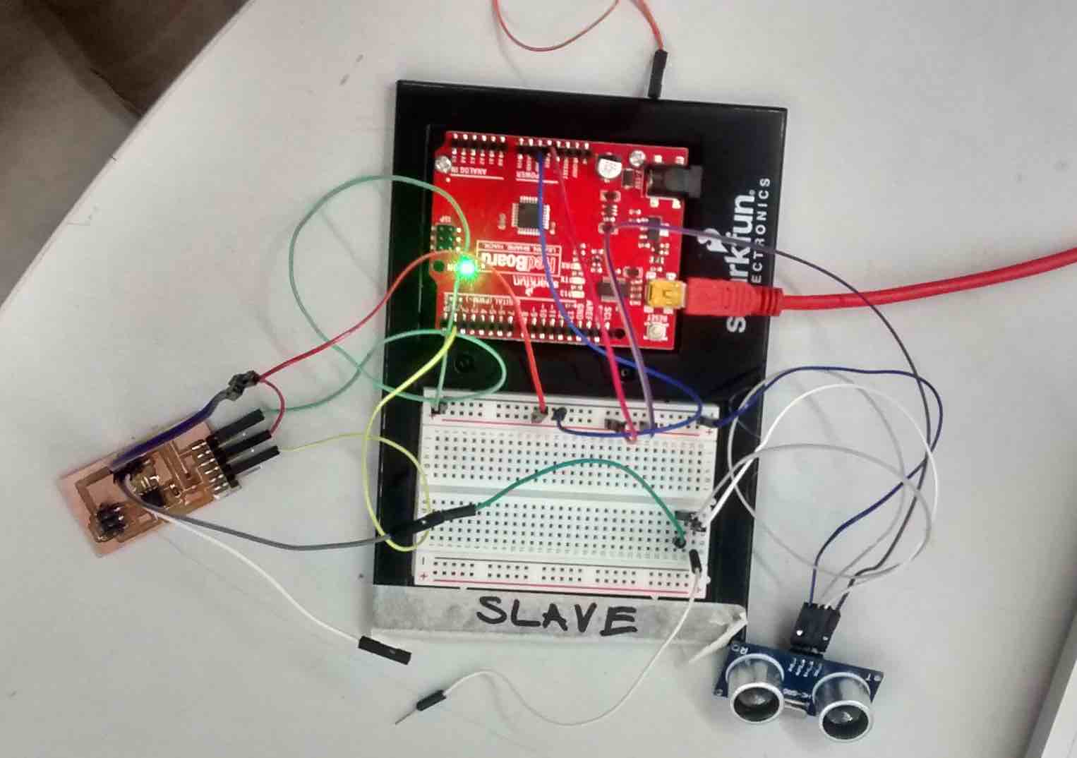
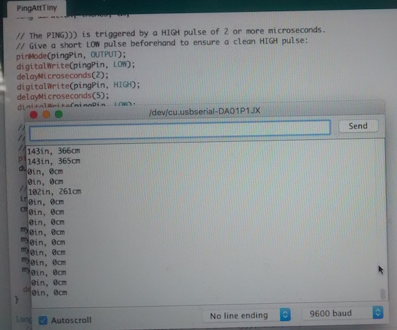
It seemed to work sort of but the results were very spotty in that it would get a measure and then stop. Which is pretty remarkable the way the everything was connected. As can be seen in the picture there were mostly 0 reflecting no input and with some distance input displayed. At least part of the problem was that although the trigger pin was at least hooked up here it was not defined in the code so with out a trig to set the ultrasonic sensor it was at best just randomly producing signals. Finally given that the TX pin from my board was hooked up to the TX pin on the Arduino I cannot discount that any data produced was just the result of random noise.
Conclusions about the Ultrasonic with ATtiny
I would like to start by asking the reader to keep in mind that when I was first trying to get the ultrasonic sensor working with my ATtiny board I was basically clueless about programming and using microcontrollers. The fact that I have been able to go back and enumerate all the things that I messed up reflects I hope a much better understanding of the process.
My other final thought is that I am not sure if there wasn't still a problem with the software and getting the software serial to work properly with the Ultrasonic ATtiny board. Admittedly at the time I was first working with this board I barely even understood what serial did or was so it was very difficult for me to even really understand the challenge of using serial with ATtiny processors. The results suggest that running the transmitting through signal through the Arduino is a workaround worth trying, if an inelegant one.
\Using the Arduino and the Ultrasonic sensor
Ultimately I decided that I has much as I wanted to get the ATtiny boards working with the ultrasonic sensor, the addition of the LCD screen and a second Ultrasonic sensor would mean that I would need to use an Arduino clone anyway. (See my final project page for the process on building the Arduino and programing the Arduino
To download the Arduino ultrasonic sketch that will read in inches click here.
). To use the Arduino I used a bread board as well as FTDI basic. I first plugged the ultrasonic sensor into the bread board. I ran the voltage and the ground to the bread board and then ran both the ultrasonic sensor and the Arduino clone off of the bread board. I then ran a jumper from pin 7 to echo on the ultrasonic sensor. For trigger I used Pin 8. Also I ran the TX pin from the Arduino clone to the RX pin on the FTDI basic. (For the pin arrangement for the Arduino clone go to here ..Changing the input code
One thing that I wanted to do was see if I could change the Arduino code to inches and have the units display on the serial output. I did this by changing the value for CM to 74 that is rounded up from the actual 73.746 microseconds per inch that sounds travels. I then divided by 2 so as to account for the fact the sound wave has to travel out and back. // second
To download the arduino ultrasonic sketch that will read in inches click here.
When I hooked up the ultrasonic sensor to the Arduino board it seemed to measure inches very accurately. I tested it by using a ruler and placing my hand at various distances from the ruler. As I moved my hand back and forth it can be seen in the video that the data closely reflects the position of my hand on the ruler.
Final Thoughts about ultrasonic sensors
One interesting insight I had when reading about the ultrasonic sensor was that I am not sure how much the addition of bat ears will change the ability of the sensor to work. In reading the data sheets on how they work it seems that the ultrasonic sensor sends a narrow ultrasonic signal out. In fact if the sound waves were to actually bounce of an ear to the ultrasonic sensor I think having bat ears would actually interfere with the signal because you would have multiple signals hitting the sensor. Remember the ultrasonic sensor works by emitting a signal and timing how long it takes to return. So even assuming the bat ear could reflect a sound wave to the sensor it would necessarily have different timing due to time taken bouncing off the ears. Thus I am no longer planning on adding bat ears to my goggles.