Exercise 7: Computer-controlled Machining
Making something big: A step Stool
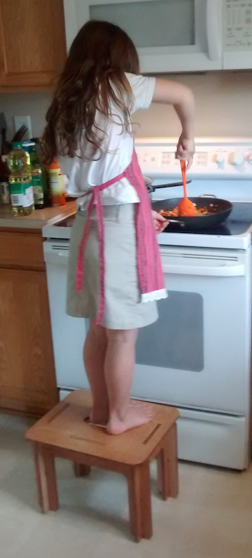
I originally was going to make a Shaker style bench to go along with a dining room table I made several years ago. When Chris from ShopBot came to give us an in service on using the ShopBot I designed one on Vcarve. Vcarve is a pretty easy program to use the only problem with it is that there is no Mac version which makes using it kind of a pain because I can not use my own computer. Anyway I designed a straightforward mortise and tenon bench with some pretty nice carving details. I ultimately decided not to do this project yet for a few reasons. One it is big and I want to make it out of quality wood to match the cherry of the table, which means it is expensive and I do not want to mess it up. I decided to start out with something smaller that was equally needed. My daughters are getting into cooking but they are not quite tall enough to comfortably work at a counter, especially for chopping. My wife said a step stool for the girls would be very appreciated.
Originally I wanted to make a step stool that had basic mortise and tenons. I found a great design I really liked. One thing that was particularly nice about this stool is that it shows a really nice example of workflow but without digital design. click here One challenge I thought of with the design was that it had legs that slanted out at an angle, which I am not sure how the joint could be cut on the ShopBot with the router bits we have. Obviously with the right router bits it would be possible but we only have straight router bits and I am not interested in buying bits for this project.
I was considering just making a stool with vertical legs rather than slanted when my wife found a design for stool that used interlocking parts. I seized on this as a perfect project because it would better utilize the skills being developed in this course. Designing straight tenons on Vcarve is not trivial but it is also true that it is something I could easily do using my hand router. I felt that making a step stool using interlocking parts would fit the Fab Academy goals because of the parametric pieces we learned to make in week two and it would better utilize the capabilities of a ShopBot. In other words I did not want to make something on a ShopBot that I could probably make more easily by hand just for the sake of using the ShopBot.
Starting with the design an Instructables Design
The instructable design I started with can be found by clicking here I first tried making a hand sketch on graph paper. This exercise helped me get familiar with some of the design parameters before I attempted to digitally design it. In particular how to set the slots on the top platform and the slots for the legs.
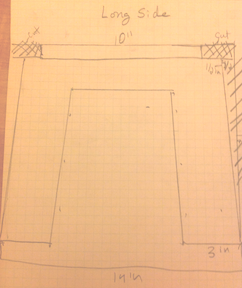
I wanted to make my design based on the Instructable design but with shorter legs. I first tried to just outlining the original design but making the legs shorter. I did not like this because I could find no way to make the legs rounded at the bottom since I could not trace this part. It did occur to me that could just shift up the original and trace the bottom of the legs.
Mostly I abandoned this approach because I was not keen on just tracing something. Even if I was going to base my design on someone else's I still wanted digitally build it myself so that I could inflict on myself the pain of going down the Inkscape rabbit hole because isn't that what this is all about.
3/10/2016
I learned a lot in making my design. The first thing I learned was how to round the corners of a box and then skew the box. This has the advantage of easily making rounded corners and keeping a flat bottom. The next thing I did was build the side pieces by merging shapes together. This was pretty easy but one thing I am learning about digital design is that it is easy to get obsessive about insanely small levels of tolerance. I know from woodworking that this is needed. My wife often jokes with me that that is why she is the carpenter (she has a degree in architectural preservation) and I am the woodworker because she has no problem living by the credo “Caulk and paint make the carpenter I ain’t”. For me it must be perfect and I often find myself obsessing about very small tolerances that in the end exceed the abilities of the machines we are using which was demonstrated when using the 3D printer and milling our circuit boards. I tried to keep this in mind when building my step stool but it was difficult to know what really mattered and what did not.
I did not try to cut this version out but here it is if you want to look at it. To To download my Inkscape file for wood with slanted legs ShopBot version ( click here.
Making Slanted legs requires CAD
In talking to Terence about my design it became clear that it was impossible to know if the pieces would fit together due to the slanted leg design. When I first talked to Terence I was only concerned about the fact that it was very difficult to center the slots both because I had already merged the pieces together and because Inkscape treats slanted objects as a vertical box and thus does not center slanted object very well. A perhaps even bigger problem that I had not even thought about was that I did not take into account the tenons that would fit into the mortise would be at an angle. I was concerned about how to space the mortise on the top step plate but it had not even occurred to me that I would have to consider the width of the mortise due to the angled tenon. In fairness to the original design if you go down through the comments he has a CAD drawing with a close up of the mortise and tenon joint for the top plate. The operative word being CAD, which is basically what came out of my conversation with Terence; only a CAD program was going to tell me if my pieces would fit together and give the angled pieces there was not good way to do that without a CAD program. He recommended to redraw the step stool with straight legs.
Making my Stool with Straight legs
I have redesigned it to have straight legs. It made it a lot easier but that does not mean there were not still many ways for me to mess up as learning opportunities. Over the last couple of days I have remade the step stool several times each time because I came to a mistake that I could not fix. This was one of the biggest lessons I learned using Inkscape. When you are building something by merging do not actually merge the objects until the very end. Even still make sure you keep a copy of the unmerged build off to the side. For example yesterday I rebuilt it and got all the way to the end and realized that one of the legs had shifted down compared to the other and that one of the tenons was off center. It would have been a pain to fix no matter what but it would a lot less so had I kept the individual parts but because I had already merged them I had to start all over.
Having said that it also demonstrates one of the powers of digital design. One of the big points Chris from ShopBot kept emphasizing when he spent the day at Latin was that many mistakes can be found when you zoom in and look at the objects closely. As such because I was able to compare my objects and especially zoom in I was able to catch the mistakes before I made the even more painful mistake of wasting a piece of wood. One general note that I take away from my time using Inkscape is that I understand now why people use cad programs for this stuff. While you certainly can draw out the objects in Inkscape it is a pain when you can fit them together in 3D to see if they will fit. Now that I am using straight legs I am much more confident about my measurements for the slots on the legs and mortise and tenons
Some general notes about working with the pieces.
-Group but do not merge pieces until the end. However note that the pieces that are grouped will not merge so you must ungroup to merge.
-Cloned parts will not merge unless you delete the original parent so it is probably not worth making parts through cloning.
-When subtracting one piece from another, Inkscape will subtract the object that was made second, so it is important to make the pieces in the order I describe below. If for some reason you need to remake a part just cut and paste the part that needs to be subtracted and then it will subtract.
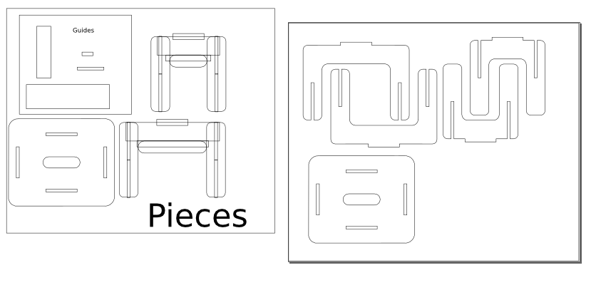
- To see all the pieces scroll down to view pieces and final layout.
How I built my step stool using Inkscape:
Step 1 Consider going to Ikea.
Just kidding their plastic step stools only belong in kid’s bathrooms, my wife wanted a nice one that we could keep in the kitchen so the girls could help cook.
Step 1: Create the following pieces:
Set the line width to .001. I used narrow lines so that the line width would not factor into my alignment.
Make the legs.
1. When you draw out the first leg set the parameters in the box 6” H X 3”W. Round the first leg by clicking on the rectangle until two small circles appear in one corner. If you see arrows keep clicking. Click on one and drag it away from the corner until you get the desired roundness.
2. Copy and paste 3 more.
Make connecting rail:
1. Make box for short side: 12” w x 3” h
2. Make box for Long side: 15”w x 3” h .
Make Tenon: Create a 1” h X 5” w wide box.
Make the Lower arc:
There are two parts you need to make for the short side. You are going to make an arc that you are going to merge to your connecting rail.
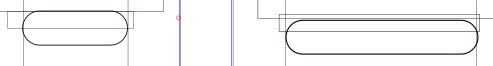
1. For the short side create a rectangle with curved corners 6.012w” x 2” h and a rectangle with square corners 7” w x 1” h.
2. For long side create a rectangle with curved corners 11.012” x 2h and 12”w x 2” h and
Create the slits for the Legs:
First create four 0.5” w x 6.05 h rectangle. Note that you will have to adjust for the actual width of your plywood. To see how we made our gauge tester see Richard’s Fab page click here.for how to make the gauge. To use the gauge you slip the various slots until you get the fit that you want. In my case my ½” plywood was 0.482”.
Pieces for the top:
Create a rectangle that is 17h x 14”w. Round the corners.
Create four 5”h x ½” rectangles.
Flip two 90 degrees.
Step 2: Putting it together
(remember do not merge anything until the end and until you have created safe copies that are set off to the side.)
Putting the legs in place:
Place two horizontal guide lines 17” apart and with a little space to the right place two more that are 14” apart. To do this click on the left side ruler and drag right.
Then click on the link to see the coordinate position. Set the position to an even number so that it will be easy to set the next line 17” away. Do the same with the other lines.
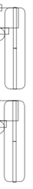
Take each of the legs and place one each next to your guidelines. (note: See below for ruler picture)
Use the ruler tool to check to make sure they are exactly 11” apart and 6” apart respectively. To do select the ruler tool and then click on the outer edge of left most leg and then drag right. Note that the ruler tool will not give you measurements of grouped or merged objects and the ruler will default to guidelines if they are close to what you are trying to measure so in this case you would not want guidelines on the interior side of your legs.
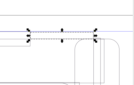
Connecting the legs
Take the 3” x 12” piece and the 3” x 15” pieces and place them between the legs.
Next group the two legs pairs so that you can align your connecting piece. First align the piece to the top of the rectangle aligns to the top line of the legs and then center. To do this for both sets of legs and then ungroup the legs.
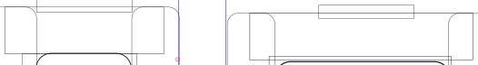
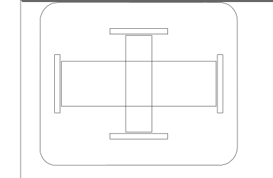
Top Tenon
Use the 1”x5” piece and center it on the connecting piece
Place it halfway down so that ½” is above the connecting rail.
Note you will need to adjust this as well as the legs slits to the actual width of the plywood. I actually forgot to take this into account and had to sand down the tenons so that they were smooth.
Bottom Arc
Take the 1” x 7” rectangle and the 2 x 6.012 oval.
Center the oval to the bottom line of the rectangle and center it horizontally as well.
Group and align to the bottom of the rectangle that connects the legs and then center. Ungroup rectangle and oval.
Place two stacked slits on each of the four legs.
Leg Slits
You will have eight slits. For the purpose of making sure that they align properly you will put two slits on each leg such that they are stacked. Align them so that they abut each other. This is important that lines making up the legs are as thin as possible, in fact if they are very thin it may not appear that the lines are touching but the as far as Inkscape is concerned this as close as you can get them. This way when you put the legs together they will be flush with the end.
I was not sure if the legs would fit flush. One thing that I did to check was to print it out on an 8x11 piece of paper. To do this in Inkscape I first select all the objects and then scale them down using the % option. This will ensure all your dimensions stay the same. In fact I found that when I made a scale model my legs did not meet up flush at the ends. I then fixed this in Inkscape as described above.
Group them and then center them to the legs both vertically and horizontally. You should have a small bit of each slit sticking out of the top and bottom of the legs. This is to ensure that when you subtract the slits it cuts an open slit.
Group all the pieces of both sides and then align them so that they at the same Y coordinate. Create a horizontal guideline to make sure all the slants meet at the same point. Once confirmed group all pieces.
Use the ruler tool to make sure all the pieces are centered and are at the correct position.
Once the slits are in position ungroup them and delete top slits from the longer piece and the bottom slits from the shorter piece. Next you are going to cut the slits out of the legs. To do this you will select a slit and the leg you want to cut. Next in Inkscape select Path and select difference. If it does not work it is because of one of two reasons. Your objects are clones or they are grouped.
Placing the top Tenon
You will have four top tenons that are 1"X5". Centering these can be tricky because the top tenon cannot be double checked using the ruler. I recommend making boxes that span from the edge of the tenon to the outer edge of the leg slit. Then make sure it is the same distance on both sides of the tenon using the rectangle. In my case this was sufficient to find if the tenon was not properly aligned and I was able to fix.
Finally you will create a union of the cross piece and the top tennon. It is at this piont in it important to take into account the thickness of the plywood. The height of the tenon above the cross piece should equal the thickness of the plywood.
Arranging the pieces for the top
To make sure that the slits were centered I created two boxes that equaled the distance between the two inner sides of the slits for the long and short side: 13.5" and 8.5" respectively.
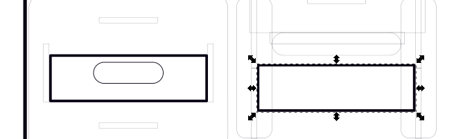
I then centered each box on both the X and Y axis. I then aligned and centered the slits boxes. Once this was done I then deleted the boxes. Lastly I created a hand hold with curved edges with the dimensions of 6"X 2"
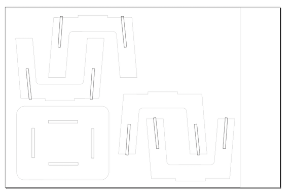
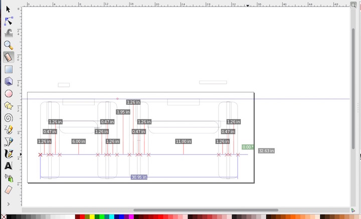
My final layout of the stool is shown below
For the PDF file that can be modified in Inkscape click here.
For the Inkscape file click here.
For the V-carve file that includes dog bones click here.
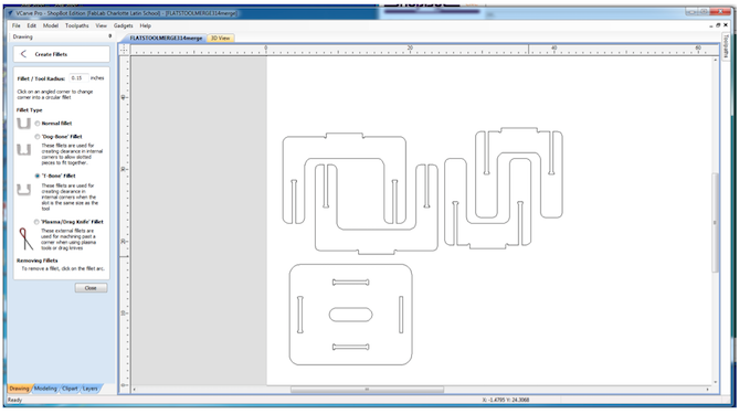
Cutting the Step Stool out on the Shopbot
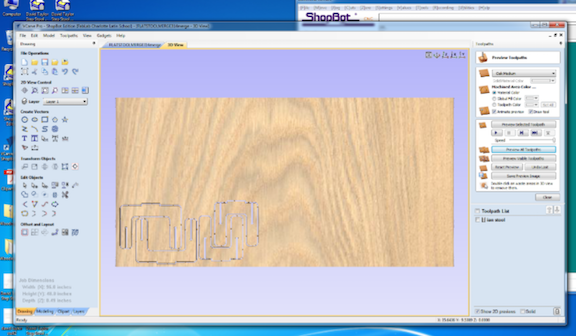
I then took my PDF and loaded it into Vcarve. Once in Vcarve I had to add dog bones so that the bit could create a flat surface for my interlocking pieces and it is because T-bones Dog bones create flat surface that I chose them rather than fillet Dog bones.
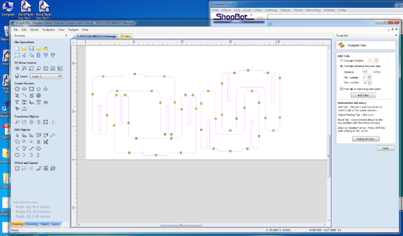
I then added the tabs. One thing that I learned was it is not necessary to add a lot of tabs. I could have easily left off many of the tabs I added and save myself a lot of trouble knocking out my tabs after the cut.
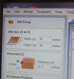
Next I had set the thickness to reflect the thickness of my wood using the gauge discussed a above, which was .48 for my particular plywood
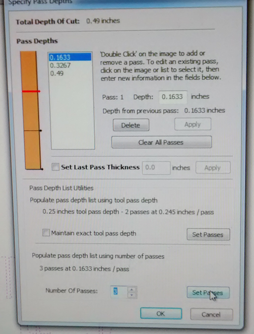
Next I checked the set depth of the tool path at 0.163 cut and the number of passes at 3. I then also selected a profile cut. I then checked the virtual tool path. It looked good so I proceeded to cutting
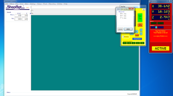
In using I learned how to zero out the XY axis. This is important because this will serve as the home location when you start the cut. The process for doing this involves using the arrow keys to move the bit to where you want the home location to be and then zeroing out the xy axis
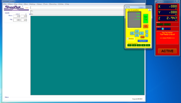
Next I set the zeroed out the Z axis. This involves using a metal plate and placing under the bit. Then when the Shopbot is set to zero out the Z axis it will lower the bit until it touches the plate. Note it is important to attach the alligator clip to the bit to ground it out.
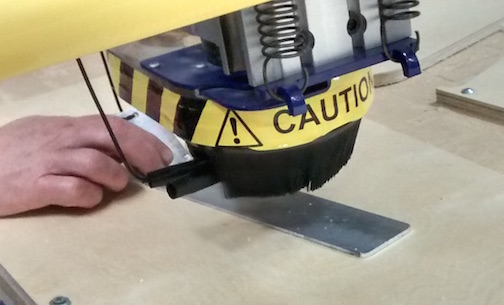
Next I cut the stool out with the shopbot. One of the most important steps and unfortunately a common mistakes is not turning on the spindle before selecting cut. I made sure to activate the spindle and then I proceeded to cut.
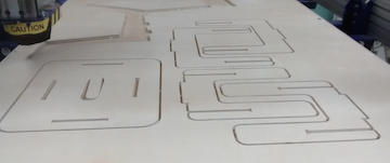
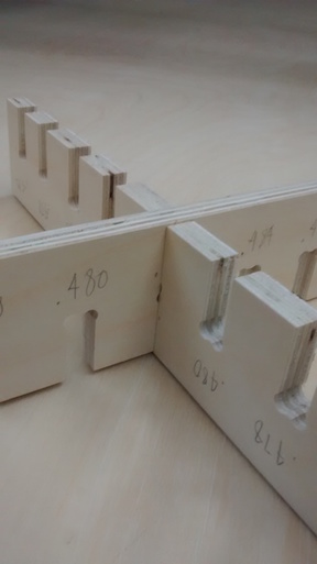
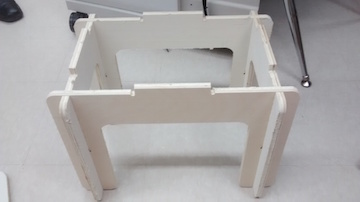
Putting the stool together
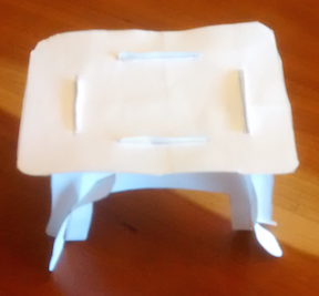
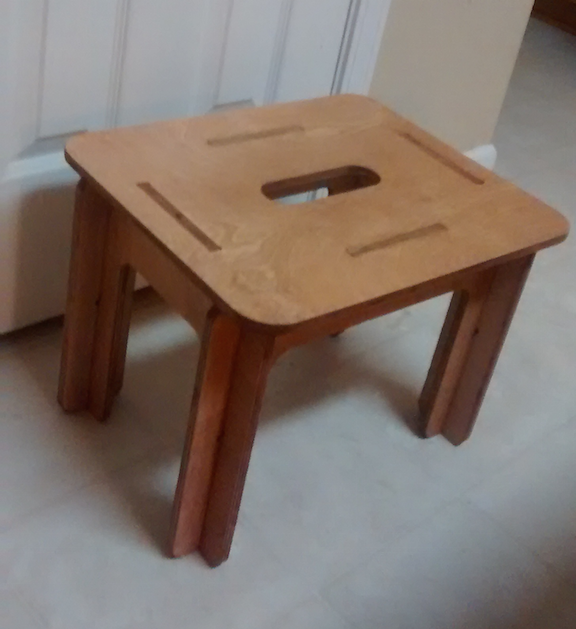
The stool easily went together. Before I could but it together I needed to sand off the remainder of the dog bones. Once I was done with this I pressed fit together the pieces of the base. Next I put on the top.
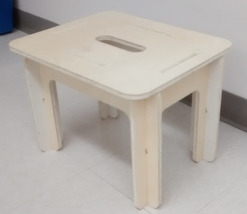
Here is my finished step stool. I stained it with a cherry stain and clear polyurethane coat. It is all press fit and no glue was used.
Conclusion
Inkscape works well for designing an objects for Shopbot. I would like in the future learn more about Fusion 360 so that I can create CAD drawing that can be assembled, thus enabling the creation of more complex structures.