Machine Design (Apr. 6)
Process
Below you will find my dictation, notes and documentation about the processes that my team and I went throught with regards to completing the Machien Design exercise and what each of us did to support this project. Each of the steps and processs will be covered in seperate sections. A link at the bottom of the page will take you to all of the files that I created for this exercise. My team is mad eup of Tom Dubick, Ian Brauner, Richard Fletcher, Brian Sossman, and myself, David Taylor.
Soldering and Board Assembly
You need to solder your board after cutting it. You will also need to create a 9 ribbon wire together or use jumper wires that are male to male using the Getting Started With Gestalt Nodes images that show you how to connect the wires. We also used a 12volt battery to power our board using jumper wires. You can see this in the video below of our first sample code test of making the motor move. The schematic of the FABNET was very helpful with wiring the 12v and GND.
Setting Up the Programming
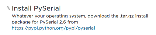
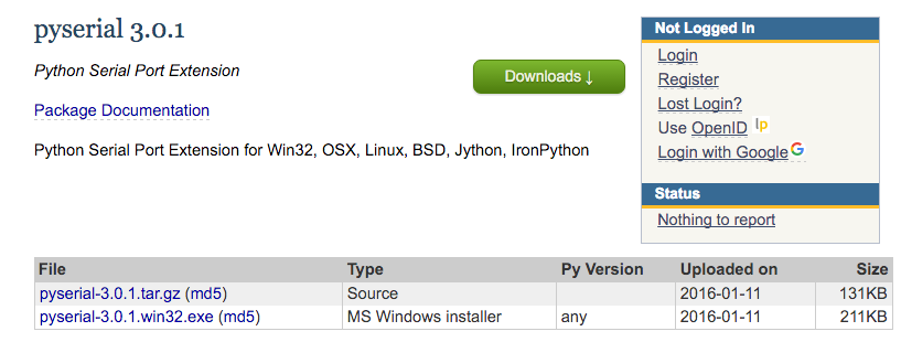
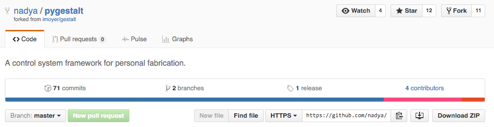
First, I went to the Fab Lab Tutorial Getting Started With Gestalt Nodes. I than click on the link at the bottom of the page for the Adafruit Python tutorial and downloaded the zip file from the pyserial zip file from the adafruit page. Next, I moved the pyserial zip file from my downloads folder to my desktop. Than installe nadya/pygestalt GitHub page and installed the unzipped folder on my desktop. I than used my terminal to complete the following unzipping process and installation process:


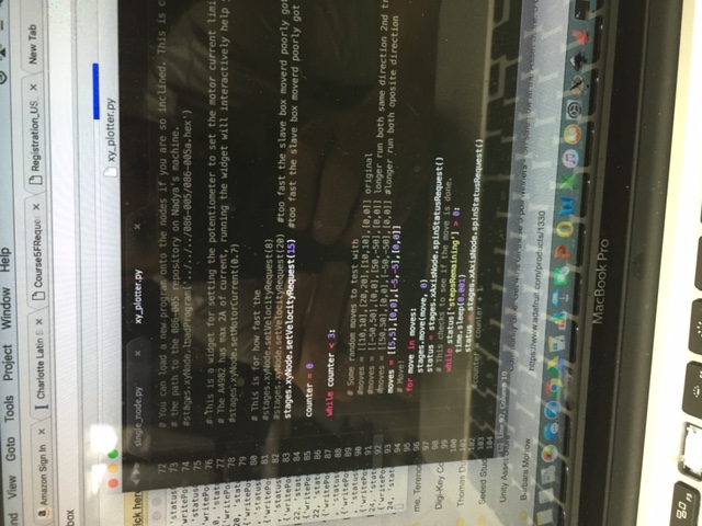
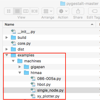
Next, I opened my text editor and opened the single nodes file from the pygesalt-master folder.

In the code, we need to change lines 25 and 77. Line 25 needs to be changed to your usb port connection. In line 77 you change this to make the moters move in different ways as well as loop it for our purposes.
Now, you need to cd your way all the way into the terminal in a similar fashion as the image below:
Lastly, the video shows the code working as well as the image shows the success of the code working:
Programming our Agitator
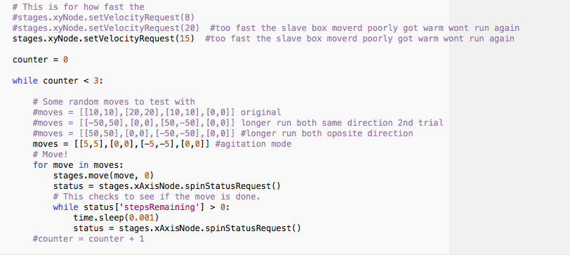
Tom lead the way on programming the agitator. He figured on that the four numbers in line 77, [20],[40],[10],[0], can be changed to make the stepper motors move differently. We were not sure if it was distance since there are for values and not just two. The four vaules allow you to move the motors along the axis as well as change the velcoity and duration. Tom added a loop to the code so it would change how long it repeated the back and forth behavior for agitation.
Button on the Boards
I learned from Tom that when I run the program, I needed to press each of the buttons for the hardware to recognize the software, which the two blue lights will come on.
Second Motor
When adding a second motor and board, you need to connect the second board to the first board using the side jumper pins. This is important so that the boards are connected correctly. It is wise to follow the diagram and images on the Fab Site. Now, you need to remove the vm file. Than restart the two motor program and press the two blue buttons and we has success.
Improved Assembly
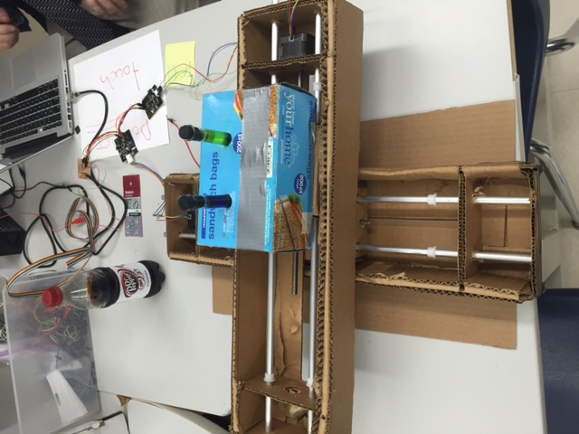
Ian and I realized we need to have a strong connection for the agitator when stacking the two main pieces. We used bottles to connect the top piece to the moving bottom piece. This allowed for the machine to work better.
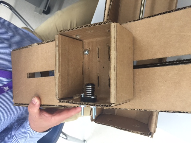
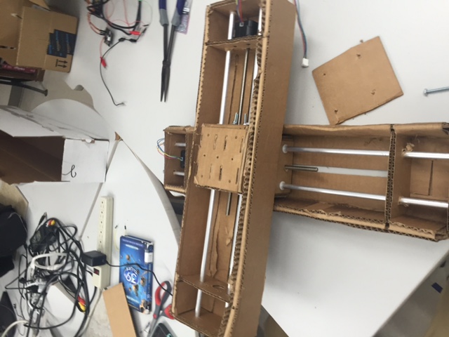
Functioning Agitator
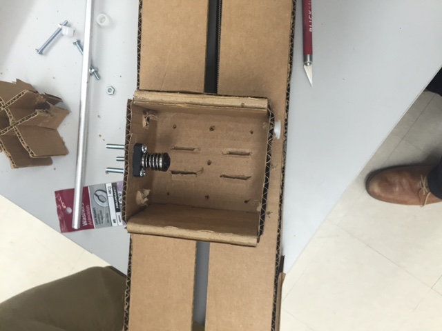
We added some weights to the other side of the top piece to counter balance the stepper motor. We than opened thexy_plotter.py file and made changes to it. Next, the velocity was set to 20 in line 83, because, 20 velocity was to high and it makes the rod slipped and jam. The moves = [[5,5],[0,0],[-5,-5],[0,0] was set after some trial and error to get the two stepper motors moving in short movements to agitate the liquid in the test tubes. These values controlled the accerlation and the coordinates on the axis. We learned that making the steppers move less witha start and stop process, we could make the liquid move more. The test tubes were filled with water and food coloring for our test, and the box had holes put in it to the size of the test tubes as well as the box was attached using velcro. I have attached the single_nodes code to show the practice we did building up towards the agiator xy_plotter code. Below you will find a video of the agitator working, images and a zip file of the code:
a