
Kati Pitkänen @ FAB LAB OULU · 2018
© 2018 Kati Pitkänen · Template by Bootstrapious

This work is licensed under a Creative Commons Attribution-NonCommercial-ShareAlike 4.0 International License.
Molding and Casting
Week 10 · [ 21.3.2018 - ]
- Review the safety data sheets for each of your molding and casting materials, then make and compare test casts with each of them. (Group Project)
- Design a 3D mould around the stock and tooling that you'll be using, machine it, and use it to cast parts. (Individual Project)
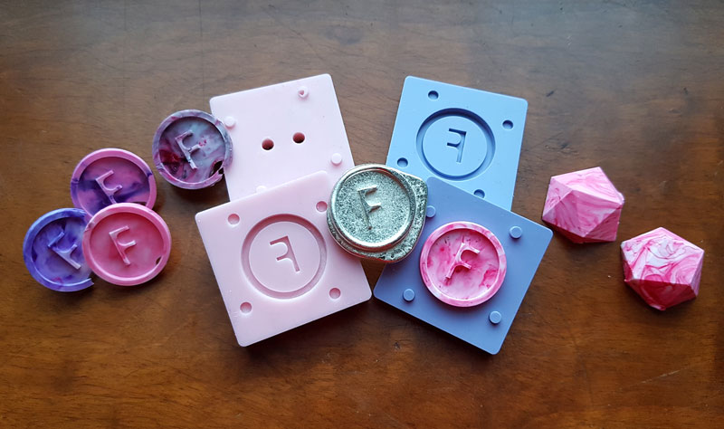
My main success this week was managing to try out casting metal! It was the first time for Fab Academy students in Fab Lab Oulu to do it, so we didn't have previous experience on that but we had to make the first experience to see 1) what should be the temperature of the oven to melt the metal but 2) keep the heat as low as possible to try if the silicon mold can resist the melted metal without breaking - and I am super happy that we succeeded in that!! Many thanks to our Fab Lab leader Jani Ylioja and this week's local instructor Iván Sánchez Milara to make this experiment true!
Another success of the week was learning to design with Autodesk Fusion 360. I have used to work with Autodesk Inventor lately, because when I moved forward from Tinkecad, I couldn't find "shared understanding" with Fusion 360 which was recommended as a next step. This is why, FabLab Leader in FabLab Silkeborg, Thomas Helbæk Petersen suggested me to try Inventor instead, which I found very natural for me and learned easily since the beginning.
However, during this week I found at least one limitation of Inventor compared to Fusion 360 because I couldn't find a way to bring vectographic image to Inventor - instead Fusion 360 has an option to "Insert -svg". This is why I decided that among ths week's assignment learning to manage Fusion 360 will be my other goal. So, I did my 3D design for molding and casting with Fusion 360 and succeeded in that! After the week, I still enjoy working rather with Inventor but now I am cleared with some of the differences, advantages and limitations of these two softwares and if needed, I can work with Fusion 360, too.
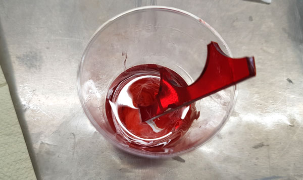
One more enjoyable moment of the week was the color tests which I got very excited. Instead of having a solid color I wanted to make marbled type colors and I had lot of good time in the fume cupboard room when doing the plastic pourings and experimenting different ways of mixing the colors!
Designing a mold with Fusion 360
When starting the week I had a clear vision in my mind that I would like to cast a Fab Lab badge made of metal to the lapel of my evening dress.
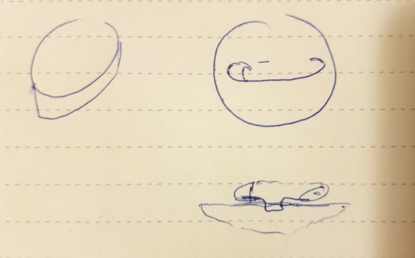
Understanding the negative and positive.
However, the first challenge I met when trying to design the badge with Autodesk Inventor was that I couldn't bring the vector graphics image (.svg) made with Inkscape to Inventor, to extrude the logo of Fab Lab. Then I found, that inserting .svg was possible and very easy to do in Autodesk Fusion 360, so I considered that this is the moment to give another chance for me and Fusion 360. I started to learn the software slowly but then I faced next challenge - the badge I wanted to design was so small (diameter 4 cm in total) that the Fab Lab logo had too small details for the 3,18 mm (1/8 inch) milling bit. In my thoughts, I was limited to this bit since it was the one we already knew the feedrate etc parameters that would work fine for milling a wax mold. I tried to redesign the badge a bit but since I didn't manage that well with Fusion 360 yet, I gave up and considered to do something I was able to create with Inventor.

My second idea was a butterfly shaped silicone pushbutton, which I designed with Autodesk Inventor. I was considering to use it in my final project but I was not sure about the final location and measurements which hindered the excitement a bit. Also, I really wanted to 1) do the metal casting and 2) learn to manage Fusion 360 so, in the end, I decided to go back to Fusion and make a third design aimed for metal casting.
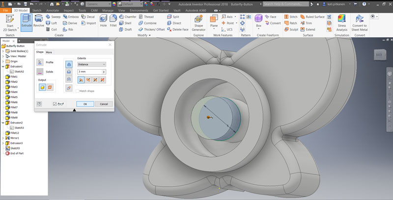
I had this pushbutton idea in my mind and I was considering how to make it by utilizing the features of metal. Then, I came up an idea of "a button" made of metal, having two "legs", which would connect/ unconnect the circuit when plugging and unplugging a metal button . Also, I was thinking that later on, when learning the software and the process of molding and casting first, I propaply could use the same idea for making that Fab Lab badge, too. However, at this point I felt I was really running out of time and I didn't have time to design any super cool button anymore, so I decided to concentrate on the features of it and just engrave a letter - 'F' for Fab - on it.
Once again, I faced a lot of moments dealing with frustration when learning to manage the Fusion 360 but FINALLY, I SUCCEEDED AND LEARNED IT!
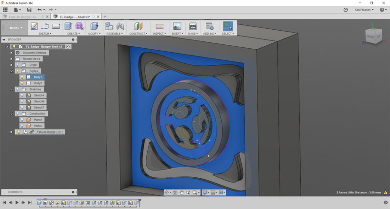
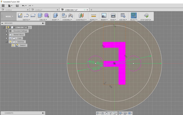
I started by designing the F-button. By navigating in the top bar, using Sketch > Circle > Center Diameter Circle -tool, I draw two circles forming the surface and frame of the button [frame width 3 mm, height 2mm of the surface]. Using Sketch > Text -tool, I added the letter 'F' on the design. Further, I draw two small circles on the back being the legs of the button.
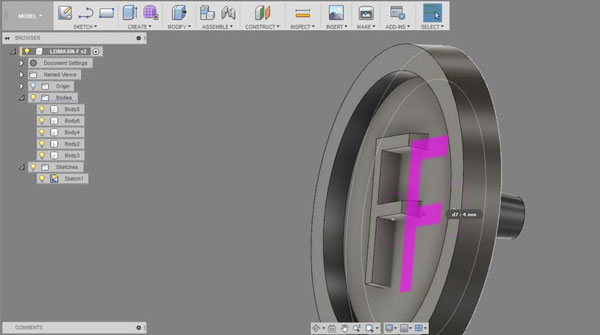
By navigating in the top bar, using Create > Extrude -tool, I extruded the surface of the button as well as the legs [6 mm]. In the Edit Feature menu I could define the starting point, direction, distance and taper angle of the extrusion. For molds it is suggested to add some taper angle on the edges for making it easier to remove the silicone mold from the wax cube, as well as the plastic cast from the silicone mold, so in this phas I added -5,0 degrees for both inner and outer edge of the frame circle and for the two legs.

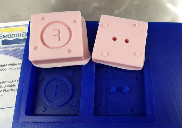
Here is the finished F-button.
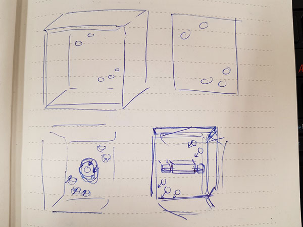
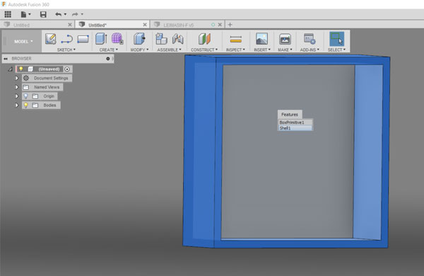
Next, I created a mold frame. Using Sketch > Circle > Rectangle > 2-Point Rectangle -tool, I draw and extruded a regtangle [50 * 50 mm].
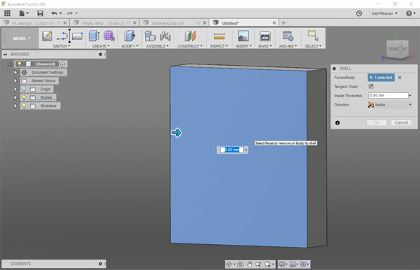
Using Modify > Shell -tool, I selected the front face of the rectangle and specified a thickness of the walls, removing rest of the material from the part interior, creating a hollow cavity.
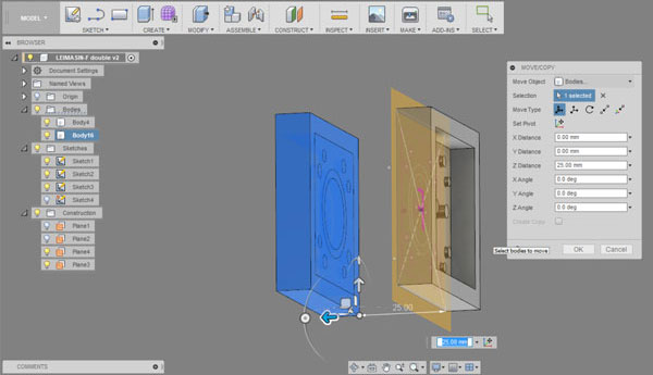
I fixed location of the button to be in centre of the shell by creating two planes using Construct > Midplane -tool and selecting the opposite faces which I wanted to divide and have the centre line in between of them.
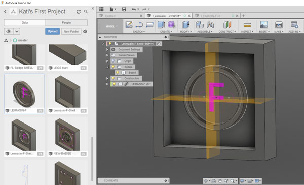
Moreover, I added a construction plane on backside of the F-button and extruded shell walls to cover the legs on the backside.

Then, I created eight more small circles, and extruded them to be truncated cones [5.0 degrees] for aligning and holding the two mold parts together. In this phase, I removed the taper angle of the legs because it would have been made the pouring hole even narrow and I considered that it should not be too challenging to remove the backside of the mold even if the legs are fully straight.
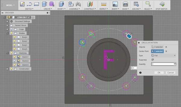
I aimed at creating both positive and negative holders, so that the hold system would have consisted of a hole circle and a peak circle pairs. This is why I created truncated cones going to both directions aiming to cut them correctly after splitting the file. I knew that single circles are not that good as holders and I would have prefared longer ones as I designed in my very first design of Fab Lab badge but I had used so much time for learning to understand the soul of Fusion that I was a little bit hurry, so I had to accept this weakness at this phase.

Using Modify > Split Body -tool, I split the design into two separate pieces.

Finally, I rotated and dragged the two molds to be side by side. And because I was a little bit hurry, I changed the truncated holder cones to point out only to one direction.
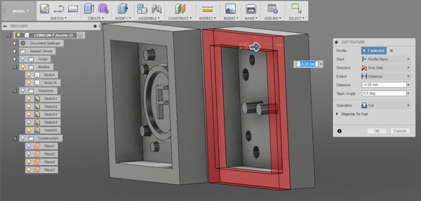
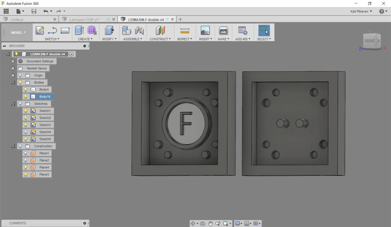
Here is the finished design of the F-button to be mold and cast. Lastly, I exported it in stl format for generating the toolpaths.

Milling the wax mold
For milling the machinable wax mold I used Roland SRM-20 Desktop Milling Machine. I utilized a 3.18 mm flat milling bit for doing both roughing and finishing milling.
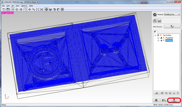
For generating the toolpaths I used MODELA Player 4 and opened the .stl file of my design in the software. Then, I checked the Material selection to be Modelling Wax.
First, I did settings for roughing, which creates the general, rough structure of the 3D design to be milled.
In the top bar, I navigated to Set > Model:
- Size and Orientation // Selected Top Surface (select correct position to be the top surface)
- Origin // Select the front - left - top -corner

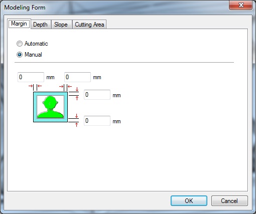
- Next, I navigated to Set > Modeling Form > Margin // Set margins to 0 (since I had already counted on the margins in my design)
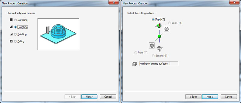
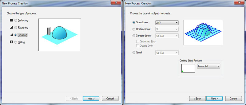
Furthermore, I navigated to Set > New Process. I utilized the settings and parameters found good last year by our local instructor Iván.
- Type of process // Roughing
- Select the cutting surface // I used the default setting 'Top (+Z)
- Tool // Flat 3.18 mm
- Cutting area and depth // All
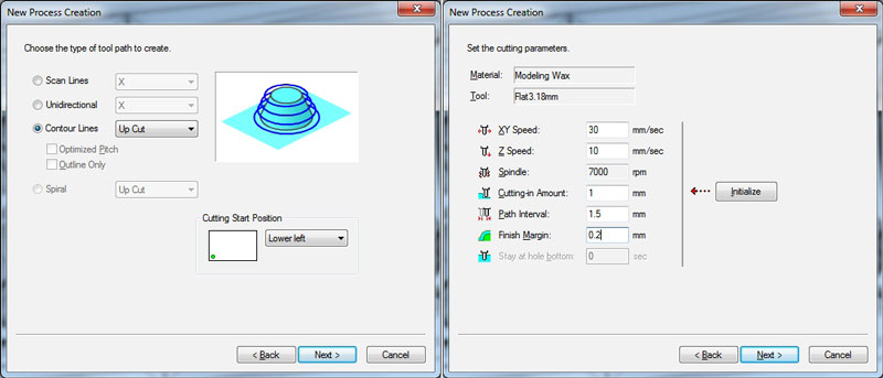
- Type of toolpath to generate // Contour Lines 'Up Cut'
- Cutting Parameters // where:
- XY Speed // 30 mm/ sec - defines the speed of milling bit to move on X-Y -orientation, increased from 10 mm --> 30 mm
- Z Speed // 10 mm/ sec - defines the speed of milling bit to move on Z -orientation
- Cutting-in Amount // 1 mm - how deep the milling bit goes on each path = the distance between vertical paths
- Path Interval // 1,5 mm - defines the steps between cutting lines, around 50 % of the diameter of the milling bit has seemed to work fine
- Finish Margin // 0,2 mm - defines un-cut part that will be left at the bottom to make finishing

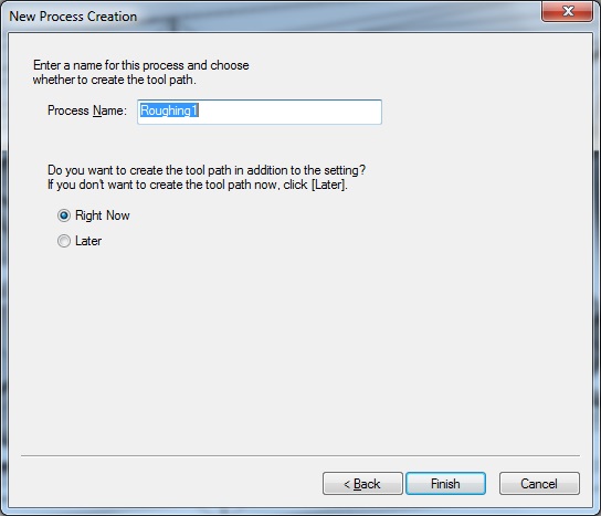
Lastly, I finished generating the toolpath for roughing and created a toolpath Right Now and hit Finish.
The toolpath for roughing:
Second, I did settings to generate the toolpaths for finishing, which smoothens the rough surfaces left after roughing, and mills the details of the design.
In the top bar, I navigated to Set > New Process. The settings I utilized were partially same than in roughing with a few differing settings:
- Type of process // Finishing
- Type of toolpath to generate // Scan Lines 'X+Y'
- Cutting Parameters // where:
- XY Speed // 16 mm/ sec - defines the speed of milling bit to move on X-Y -orientation
- Z Speed // 16 mm/ sec - defines the speed of milling bit to move on Z -orientation
- Path Interval // 0,2 mm have seemed to work fine - defines the steps between cutting lines
- Finish Margin // 0 mm - defines un-cut part that will be left at the bottom

Again, I finished generating the toolpath for finishing and created a toolpath Right Now and hit Finish.

Then, I did Set > Cutting-position Setup to check that everything looked correct: 'X and Y Directions', 'Z Direction'. At this point, it is doog idea to check one more time The Model Top-edge Depth to make sure, that there is enough depth also in the wax piece you are going to mill your design in.<

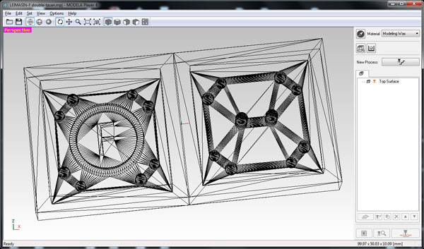
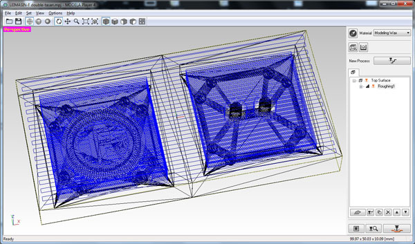
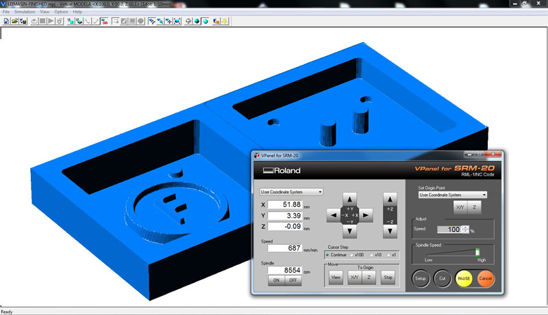
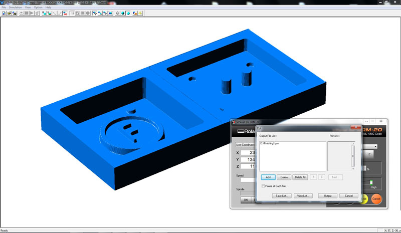
For simulating the toolpaths for roughing and finishing, I selected the process one by one and hit Preview, which opened the Simulator of the Virtual MODELA.
In Simulator, it is possible to check the generaed toolpaths. It is also possible to see e.g. an estimated time for the toolpaths by navigating into Simulation > Estimate Cutting Time.
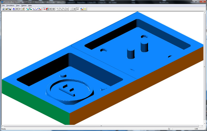
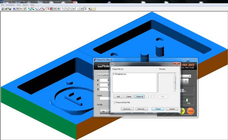
In the simulator view I found that the space between bigger/ outer circles, meant for aligning the bottom and the top of the mold with each other, was too thin for 3,18 mm milling bit. Since I had double number of these cones, I made a quick decision to remove the ones too near the edges. Then, I imported a new stl model to MODELA and made all the settings again, and simulated the toolpaths to make sure the settings are correct. Next time, I will preview the simulator right after creating a toolpath for roughing, before doing a toolpath for finishing, to see that it looks ok.
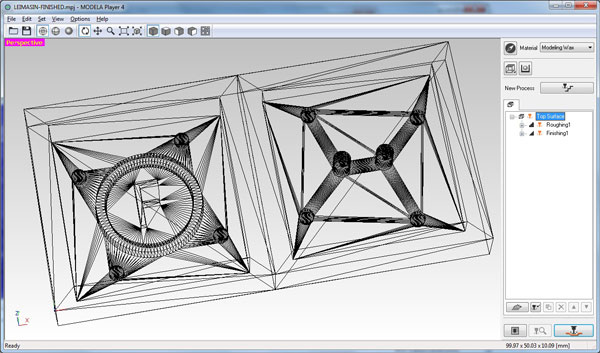
Preview of the toolpath for roughing:
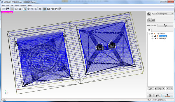
Preview of the toolpath for finishing is below. After I had defined both toolpaths, I pressed Mill to generate and export g-codes for milling: two separate toolpath files, one for roughing and one for finishing.
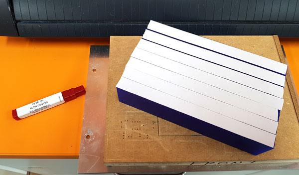
To prepare Roland SRM-20 milling machine for milling the mold, I followed the working process documented on the Week 5: I taped and placed a Blue Machinable Wax cube to the plate, put it inside the milling machine, and inserted the 3,18 mm milling bit [1/8 SE 2FL].
(1/8 = Diameter of the bit/ 1,8"/ 3,18mm, SE = number of ends/ Singe End, 2FL = number of flutes/ 2)
Then, I found the origin settings of the axes using VPanel.
First, I ran the toolpath for roughing:
And then the toolpath for finishing:
Molding silicone
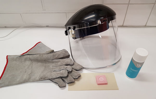
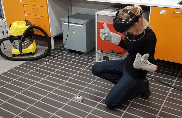
For ensuring the ventilation and safety, we did molding and casting in the separate room having a fume cupboard, and using protective goggles and gloves. For a start, we red through the datasheet of the material, to familiarize ourselves about the technical features ans safety issues.
Our group work wasn't too successful since all of the Smooth-On OOMOO™ 25 for casting a silicone had gone bad and we waste a lot of time with that, so in the end, we didn't have time to try out pouring silicone as a group but we had to do it later on individually. However, we started experimenting with casting liquid plastic. The results including a table with technological overview can be found here.
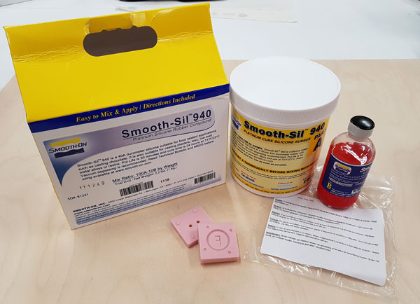
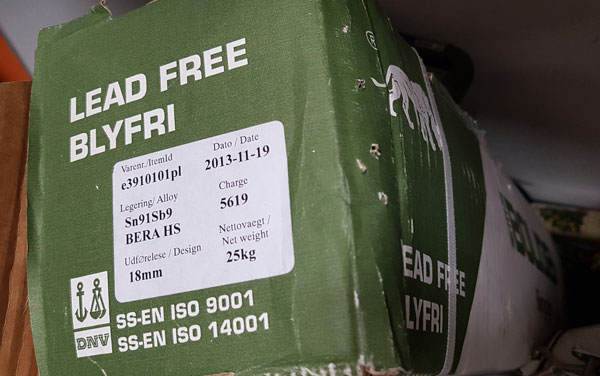
For making the negative silicone mold I used Smooth-On Smooth-Sil™ 940, which was actually quite good for metal casting when compared to the "normal" silicone since it has higher heat resistance up to 232 Celsius degrees.
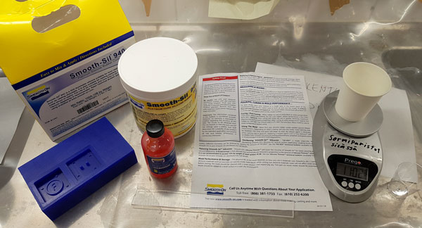
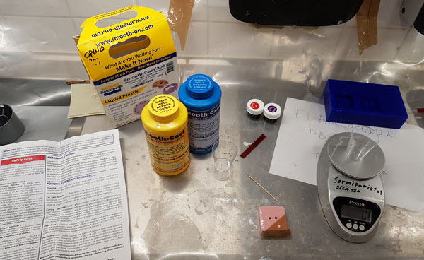
First, I prepared all the equipment I would need for the process: safety data sheet, the parts of A and B of the silicone material, the wax mold, containers and mixing sticks, toothsticks, scales, vacuum foemer, and the protection accessories (long sleeves, protective goggles and gloves).

This silicone has following technical features:
- A:B Mix Ratio by Volume // 100A:10B
- A:B Mix Ratio by Weight // 100A:10B
- Pot Life // 30 min (defines how much time there is since measuring and mixing the liquids until pouring them into a mold)
- Cure Time // 24 hours (defines how long the material has to stay in the wax mold before it is finished)
Workflow of casting Smooth-Sil™ 940:
The pot life was quite long, 30 minutes, so I had a good time to do everything without a rush. To start, I pre-mixed Part B thoroughly. Then, using a gram scale, I weighed Part A: 70 g and Part B: 7 g separately and then mixed and stirred them 3 minutes by horizontal movements trying to avoid adding bubbles into the mixture.
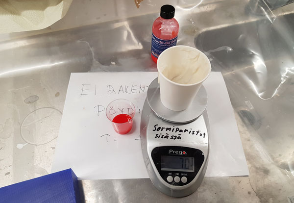
After stirring for 3 minutes, I put the mixing container into a vacuumer and vacuumed the material for 3 minutes for eliminating entrapped air as much as possible.
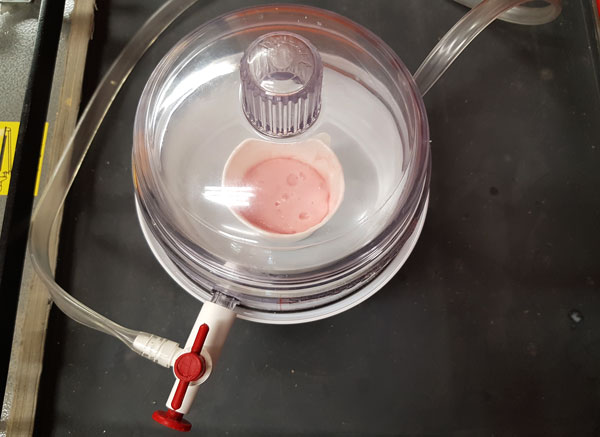
I poured the mixture in a single spot at the lowest point of my wax mold. I let the material seek its level up and over the model.
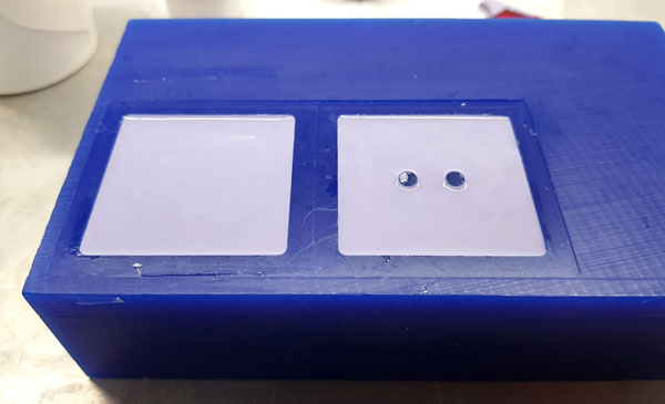
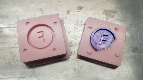
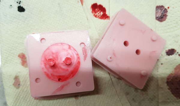
I allowed the silicone to cure on the wax mold at room temperature for 24 hours. Then, I checked the result. I was a bit afraid how would the outcome look like since - even vacuuming the material for 3 minutes - I had quite a lot of bubbles on the backside of the silicone mold. Fortunately, the front looked almost perfect (only one small air hole on the truncated cone aligning the bottom and top molds together). (Actually, this material was opened already one year ago, so I think that the quality of the material must be very good because it was still doable and the result was ok even it had been open for a long time.)

Finally, after being unlucky with all of our Smooth-On OOMOO™ 25 Liguid Rubber packages having bad 'Part A' -material found during our group work, we received new packages of Smooth-On OOMOO™ 30 Silicone Rubber and I decided to try out also that material.
This silicone has following technical features:
- A:B Mix Ratio by Volume // 1A:1B (OOMOO™ 25 same)
- A:B Mix Ratio by Weight // 100A:130B (OOMOO™ 25 same)
- Pot Life // 30 min (OOMOO™ 25 15 min)
- Cure Time // 6 hours (OOMOO™ 25 75 min)
Workflow of casting OOMOO™ 30:
First, I pre-mixed both parts thoroughly. Then, I dispensed Part A: 100A and Part B: 130B by weight into a mixing container, and mixed them thoroughly for 3 minutes observing to have a uniform color with no color streaks.

Further, I vacuumed the mixed material for 3 minutes (even the instructions did not mention that but since I could saw the bubbles on the mixture, and also because there was time enough to do that).
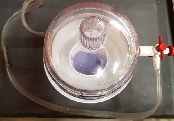
Both this and also OOMOO™ 25 have low viscosity, so they are easy to mix and pour. This time, for ensuring to get avoid of bubbles on the surface of the wax mold, I poured a little amount of material on bottom of the mold and "painted" the surface with the material. Then, I poured rest of the mixture in a single spot at the lowest point of the mold, and let the material seek its level up and over the model. To cure, I allowed the silicone to cure on the wax mold at room temperature over night before demolding (6 hours should be enough though). For post curing, it is possible tokeep the mold an additional 4 hours at 65°C, which will eliminate any residual moisture and alcohol which is a by product of the condensation process and may inhibit some resins. For now, the post curing was done only at room temperature. However, this time I got a very nice pouring result without bubbles.
Casting Smooth-Cast® 305 liquid plastic
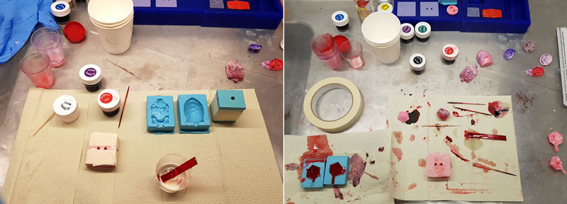
My main goal was to do the metal casting but since we couldn't sure if it would work, Iván suggested me to do the casting with plastic, too, to have at least some results. And, I was so excited about this casting part! After the challenges in the beginning with Fusion 360 I totally forgot them, and I could have continued my color tests all night long. I felt, that I only got started.
I had only one mold made by myself at that time, so I utilized also the molds done by previous years' Fab Academy students in Fab Lab Oulu: Antti Mäntyniemi, Nataliya Shevchuk, and Iván Sánchez Milara, to make my tests.

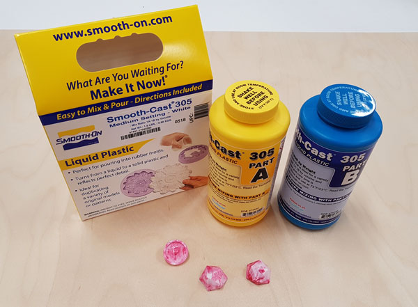
For making the first silicone mold I used Smooth-On Smooth-Cast® 305 liquid plastic, which is ultra-low viscosity casting resin that yield castings that are bright white and virtually bubble free, so there is no need for vacuum degassing.
Again, I prepared all the equipment I would need for the process.
This liquid plastic has following technical features:
- A:B Mix Ratio by Volume // 1A:1B
- A:B Mix Ratio by Weight // 100A:90B
- Pot Life // 7 min
- Cure Time // 30 min
Workflow of casting a plastic liquid:
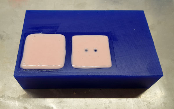
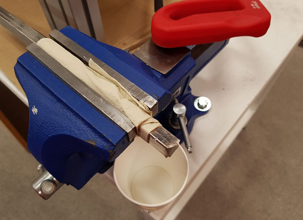
To start, I taped the front and backside of the mold tightly together, and pre-mixed both Part A and Part B thoroughly. Then, using a gram scale, I weighed Part A: 10 g and Part B: 9 g separately, and then mixed them, and stirred them 3 minutes by horizontal movements trying to avoid adding bubbles into the mixture. The pot life of this material is quite short, so I had to be quick to mix the material well, (then add the color), and pour the material into a silicone mold.
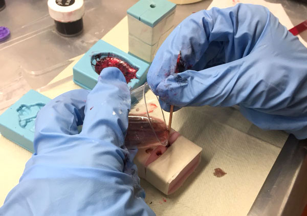
With the help of a toothpick, I poured the mixture as a very thin trickle through one narrow hole on the backside of the mold. Using toothpick, it was possible to pour the material in a single spot at the lowest point of a silicone mold, and avoid the mixture stopping up the mouth of the hole. When pouring, one hole was for filling the mold with liquid plastic, and another enabled air coming out. The holes itself were also meant to be filled, being the legs of the object. When both of the holes seemed to be full and I could not add anymore material, I let the material seek its level, and allowed the liquid plastic to cure on the mold at room temperature for 30-40 minutes.
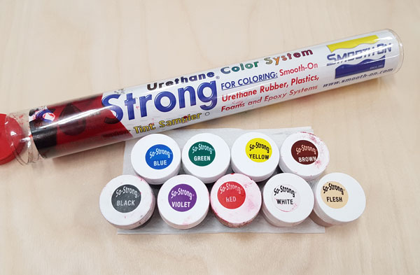
To color the material, I used Smooth-On SO-Strong® liquid urethane colorants, that can be added to any Smooth-On liquid urethane rubber, urethane plastic, epoxy or urethane foam. A very small amount will color a proportionally large amount of liquid urethane material. The processing recommendations of the colors are as follows:
- SO-Strong® colorant Mix Ratio by Volume // 10 drops of SO-Strong® per 88 ml (3oz) of mixed urethane material.
- SO-Strong® colorant Mix Ratio by Weight // between 0.01% - 3% of the total weight (Parts A + B mixed) of the material being cast.
- The more you add in proportion to the volume of liquid urethane, the more dramatic the color effect.
- It is possible to combine different colors on a palette to create a custom color before adding to material as directed above.
- Adding more than 3% by weight may cause cure inhibition or oozing.
- After dispensing the required amount of urethane material Parts A and B into measuring containers, add colorant to Part B and mix thoroughly.
- Combine Parts A and B into a mixing container and mix as directed by the urethane product technical bulletin.
I considered, that these recommendations are for creating solid colors. However, I wanted to create a marble colors, which for I should mix the dye with the urethane material only as less as necessary. This is why, I added the dye at the last moment, right after mixing and stirring the parts thoroughly. I added 1-3 tiny drops of dye color(s) (for 10 grams of material) to the mixing container and mixed only a little, by couple of careful, slow turns around the container, and after that poured the material very quickly, because the color colored the whole liquid plastic and turned to be solid color very fast.
All these hours, full of enthusiasm!
It turned out, that my design with its 2mm and 4 mm heights was quite challenging to pour and make the material find each place. Even I had the hole for the air to come out, and I raked the mold for letting the material reach and fill every place on the mold, it seemed that there was always some bubble left on the mold and cast.
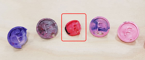
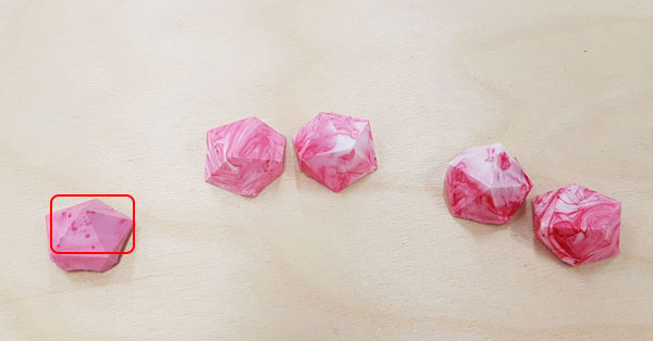
So I made a lot of trials and finally, I accepted this particular cast to be my 'final' one. For this, I "painted" the surface of the mold with the materal very quickly, then poured a very thin layer of the material on the mold without the backside of the mold, which after I attached the backside on its location and filled in rest of the mold. I did this because I had already experienced that the old, already harden material will stick into a new, liquid material without any problems or breakable seam, so it was fine to have some seconds between the two pouring times (as long as the material itself stayed pourable).
Here are the trials I made before the one above, developing my tactic and percent of success all the time slightly.

Learned about casting and coloring plastic liquids
What I learned was, that when measuring the amount of parts A and B for mixing them, it cannot be done with a gram scale which is not precise enough. When I tried to weight Part A: 10g and Part B: 9g and after measuring them separately did a few checkings, the weight usually varied +/-1 gram, so the amount I tried to scale was too small for our scale. This is why Iván suggested me to try measuring and mixing bigger amount of parts next time.
It was easy to see if the mixing ratio was correct since when it was:
- 1) the mixed material started to warm up and harden very quickly after mixing
- 2) the result was hard plastic
If the mixing ratio was not precise, the material just did not harden and the result was very sticky or there was dots consisted of only a dye.
Learned about casting and coloring silicone
One of the benefits of Smooth-Sil™ 940 Silicone - in addition to its comparatible high heat resistance - is that it is suitable for food related applications, too.
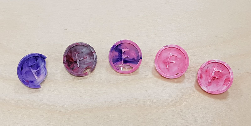
I got excited and made quite a lot of marbled color tests with liquid plastic during the week. Then, when there was leftovers of silicone, I decided to try out coloring that material, too.
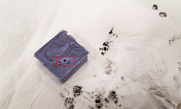
The result was nice BUT the same rule goes with this and liquid plastic - there shouldn't bee too much un-mixed color into the material because it won't harden at that particular part but leave a wet color drop inside the mold making a mess afterward.
And actually, I found afterward, that So-Strong Colorants shold not be suitable for Smooth-On silicones, but instead there is a special Smooth-On silicone color product for coloring silicones: Silc Pig or Ignite. I could not find fixed answer why, but I think silicones can take better the pigment of the dye produced particularly for silicones. However, apart from the one wet dye spot into purple silicone mold, the results seemed to be fine.

Color tests in casting liquid plastic
For creating marble type, unsolid colors, I had to unfollow the recommendations of adding a color to only one part and then mixing the parts A and B. Instead, I mixed the parts first and then, added 1-3 tiny drops of color(s) (for 10 grams of material) to the mixing container and mixed only a little, by couple of careful turns around the container, and after that poured very quickly before the color colored the whole liquid and turned to be solid color.
However, too big un-mixed drops of dye won't harden but will run out from the plastic.
What comes to colors:
- White and Fleshtone // are color pigments (Opaque)
- Black, Brown, Purple, Blue, Green, Yellow and Red // are color tints (Translucent)
Since the plastic will turn out to be white after hardening I recommend to not use white color for making a pattern but only if you want to make a light color like pink. So if you want to make some marble patterning, use only the colors different from white (and flesh) to create the pattern.
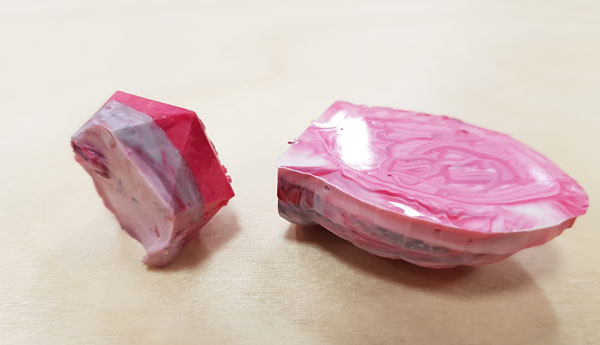
In these two in the middle, the front of Nataliya's turtle, I used white color and I don't like the outcome too much. The purple, red, and black stripes on the back part of the turtle are nicer, I think.
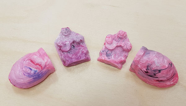
Then I found, that it is possible to let the plastic harden and afterward, add more material: the two different castings will be fully attached to each other.
Moreover, to give an idea how should the mix look and how will the result be after hardening, this series of pictures shows the color changes during the hardening process.

Some results of my color tests.
Casting metal
Finally, it was time to try out casting a metal. Since this was the first time to experience metal casting among Fab Academy students in Fab Lab Oulu, we decided to make one-side castings first.
For start, using gloves and an iron saw I cut several small parts to be melted in the oven.
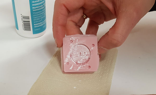
For preparing the mold to resist a little bit more heat, I powdered the surface with talc powder, and tapped the mold on the table to spread the powder evenly.
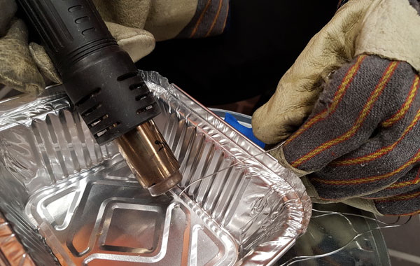
For testing to melt the metal in our oven and cast it, our Fab Lab leader Jani Ylioja did the first trial. The melting point of the metal was said to be 235 - 240 Celsius degrees but the metal didn't melt at that temperature. We increased the temperature slightly as far as we were able to see what was the minimum temperature where the metal was melted for trying to see if the silicone mold, told to resist heat up to 232 Celsius degrees, could take the hot metal without breaking. The first trial, when the metal was melted enough was on 258 Celsius degrees, which Jani poured and the result was all good - the metal was cooled down so quick that the silicone mold didn't suffer at all, the tape didn't burn, and I got one leg for my button made of metal.
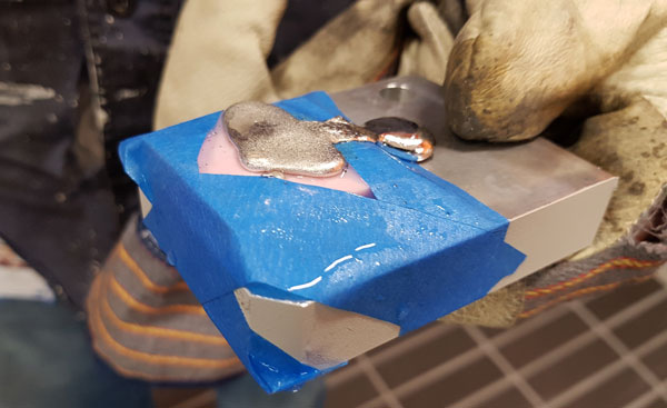
Then, it was my turn to try for the top part of the mold. The oven showed the temperature of 259 Celsius degrees. It was a little bit thrilling to take the melting container out of the oven - or put it back - without overturning it, and also see, when will the metal flow out from the container to the mold but I succeeded quite good.

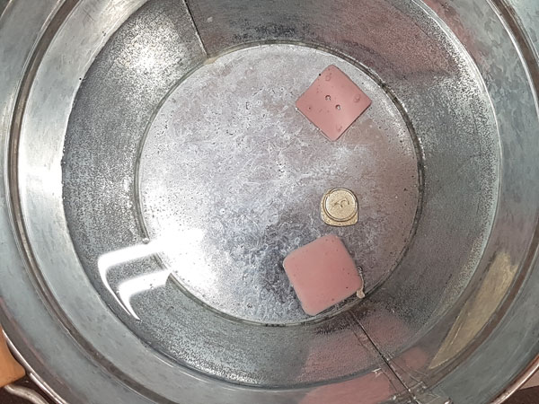
Cooling down the metal cast in a bucket of water:
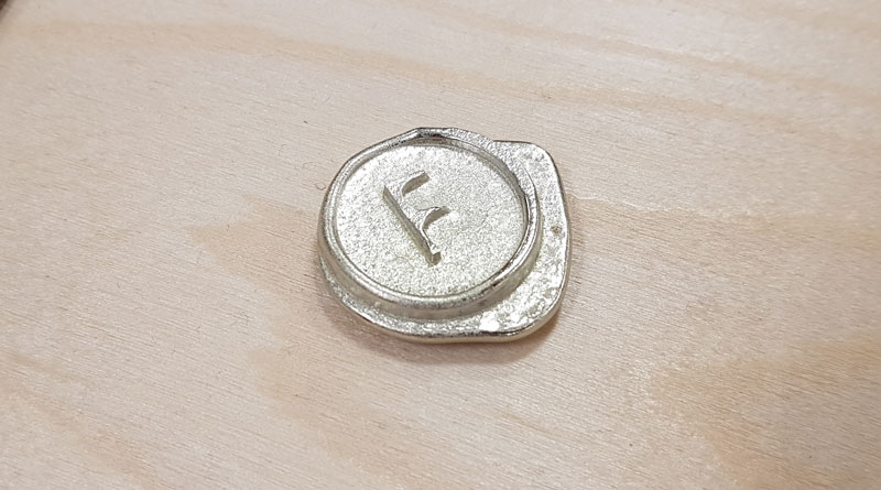
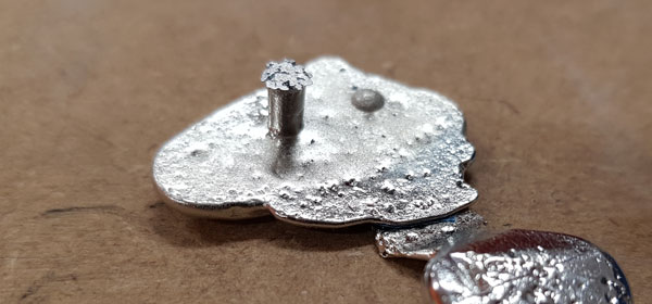
The result of my metal casting:

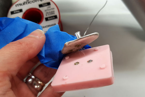
Moreover, I experimented trying to do the legs for my metal button with soldering tin. First, I tried melting the tin by hot-air gun, using a tin both with and without lead, but that didn't melt the tins enough.
Then, I tried also built the legs with soldering iron by melting the tin straight through to the holes. I managed to build quite solid legs but the problem was in attaching them to the metal cast. So it didn't work that well. What I might try to do in the near future is to cast the metal again using a closed, two-sided silicone mold.


Here are the files of my F -button I designed, mold and casted this week.
- Fusion 360 design file of F-button in .f3d format
- 3D model of F-button in .stl format
- Milling toolpath for roughing the F-button in .prn format
- Milling toolpath for finishing the F-button in .prn format