Smart Waste Bin
In Fab Academy have to make a product using the machinery and skills we learned from Fab Academy. Actually, I am from Computer Science background and interested in doing embedded projects, I thought of making something use full for the society. One of the main problems in our Society is waste management, and my plane to make a device that can make the waste management's jobs very easy. Here my final project I going to Build an IoT Project, and it can also contribute to Fab City project.
The Challenge
The waste collection process is a critical aspect for the service providers. The traditional way of manually monitoring the wastes in waste bins is a complex, cumbersome process and utilizes more human effort, time and cost which is not compatible with the present day technologies. Irregular management of waste typically domestic waste, industrial waste and environmental waste is a root cause for many of the human problems such as pollution, diseases and has adverse effects on the hygiene of living beings. In order to overcome all these problems, we are proposing the idea of the smart waste management system which helps in auto-management of waste without human interaction in order to maintain a clean environment.

Currently, most municipal waste collection operations focus on emptying containers according to predefined schedules at a set frequency. This system is inherently inefficient, with half-full bins being emptied, poor use of city assets, and unnecessary fuel consumption. Smart solutions—for tracking waste levels, route optimization, and operational analytics—offer municipalities and waste service managers the ability to optimize waste management services, reduce operational costs, and better address the environmental issues associated with inefficient waste collection.
Most waste companies still operate using a traditional collection process, whereby bins are lifted on fixed days and static routes. This is highly inefficient, as trucks drive a considerable distance to collect bins that aren’t full. while ignoring others that are overfilled.
As a result, logistics costs are too high, customer service is poor and carbon emissions are through the roof.
Root cause is the lack of visibility on bin ‘demand’. Wouldn’t it be great if bins could do the talking? This is now possible by Internet of Things.
The Solution
Sensor Based Waste Collection Bins is used to identify the status of waste bins if it is empty or filled so as to customize the waste collection schedule accordingly and also save the cost. The real-time waste management system by using smart bins to check the fill level of smart bins whether the dustbins are full or not, through this system the information of all smart bins can be accessed from anywhere and anytime by the concerned person. It will inform the status of each and every dustbin in real-time so that concerned authority can send the garbage collection vehicle only when the dustbin is full. By implementing this system resource optimization, cost reduction, effective usage of smart bins can be done.

The network of sensors enabled smart bins connected through the cellular network generates a large amount of data, which is further analyzed and visualized at real time to gain insights about the status of waste around the city.

Benefits of using Smart Bins
- It will stop overflowing of waste bins along roadsides and localities as smart-bins are managed at real-time.
- The filling and cleaning time of smart bin will also be reduced thus making empty and clean dustbins available to common people.
- By using the route algorithm it will smartly find the shortest route thus it will reduce the number of vehicles used for garbage collection.
- Send optimized routes directly to drivers
- It will reduce fuel Consumption.
- Improved customer service by lifting bins that need a collection
My Project Planning
Project is divided in to Five categories ,
- Electronics
- Programming
- Application/Cloud Development
- 3D Designing
- Mechanical Structure
Electronics
Block diagram
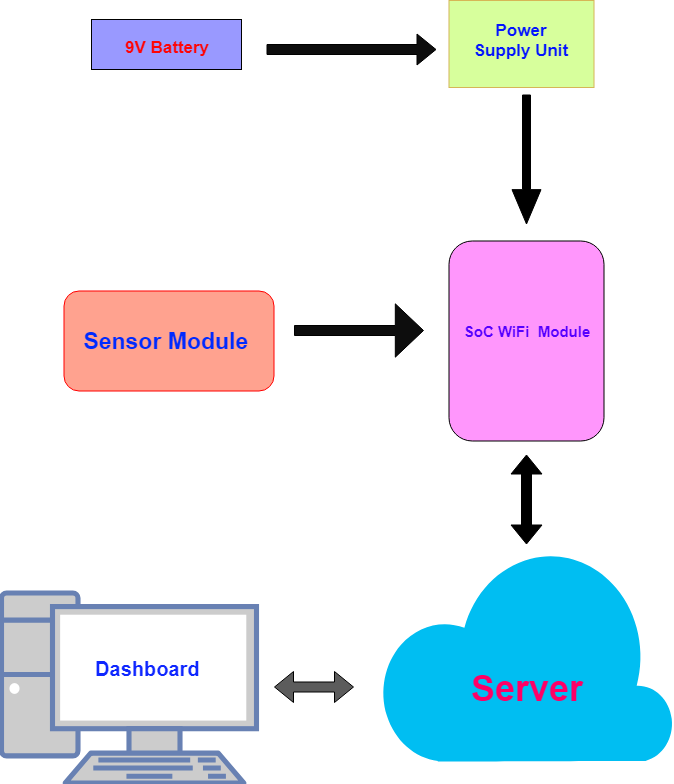
Sensor Module
Finding the suitable electronics components for my project is a challenge, So I started searching for good Distance Sensor, and I found that most of the modules have a huge price tag, and I found HC-SR04 is the one with low price and moderate accuracy and it's available in the local market. and in the input week, I tested it with the Atmel ATtiny45 and I built a miniature WasteBin Model . and it's worked as expected to measure the waste level.
For more details about the miniature WasteBin Model check my Input Week page.
SoC / Microcontroller Module
Normal Atmel AVR microcontrollers not suitable for my project, because it doesn't have any inbuilt connectivity and I need to send sensor data to the server, so choose ESP8266 WiFi SoC (System on Chip) because I did some experiments using its development board Nodemcu and it's well suitable for me and it's very cheap .


ESP8266 is powerd by Tensilica L106 integrates industry-leading ultra low power 32-bit MCU micro, with the 16-bit short mode, and Clock speed support 80 MHz, 160 MHz, supports the RTOS, integrated Wi-Fi MAC/BB/RF/PA/LNA, on-board antenna . In overall we don't need to use any other MCU in order build our Internet Connected Product (Datasheet)
normally esp8266 comes as a NodeMCU Development board. but I don't want to use the development board, I want to build a custom board for my product, so i googled a lot of time but no luck didn't find any minimal schematic, so I built one based on the dashboard. and i opensource in GitHub. here you can find ESP8266 12-E GitHub Repo
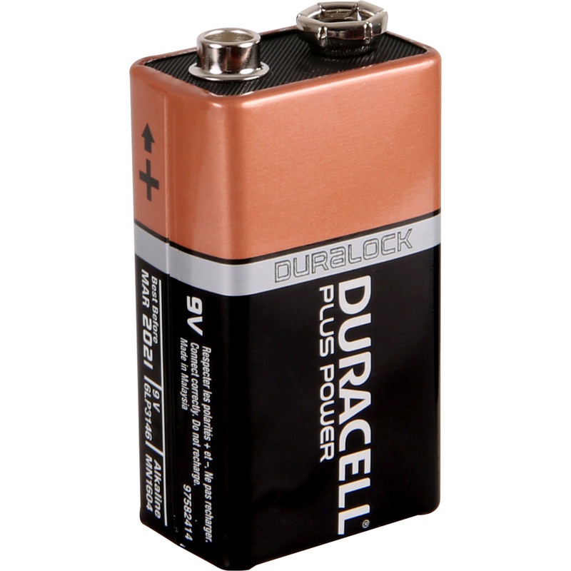
Power Supply Unit
ESP8266 need 3.3 v so I used NCP1117 LDO Voltage Regulator with 9v Alcaline battery.

PCB Designing
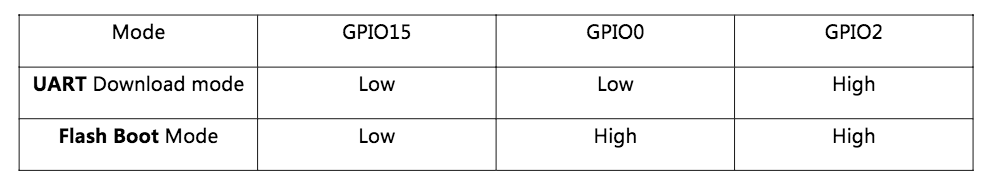
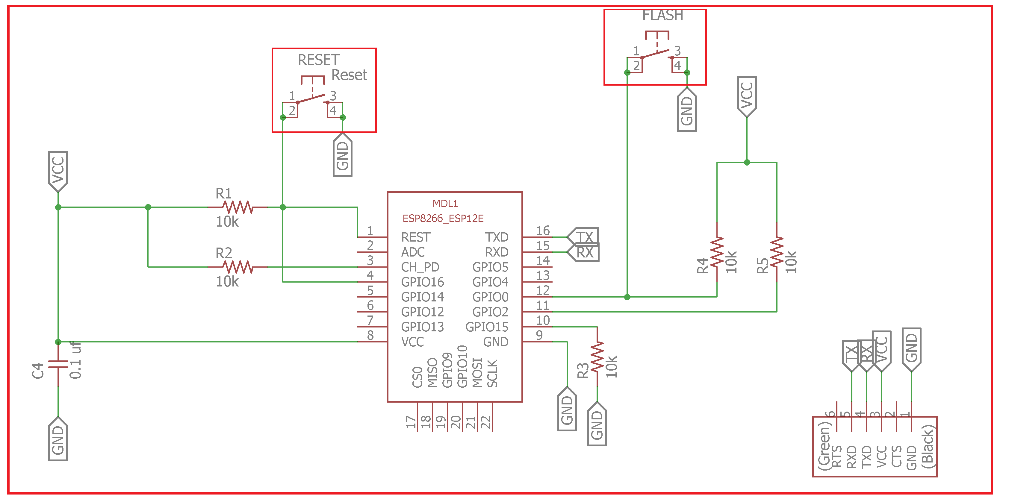
I satretd Design with eagle .In ESP8266 we can't really use every pin , config's are controlled by some pin's that's like fuse bit's in the AVR microcontrollers, so first i designed a Minimum Config ESP8266 Board that can switch between UART Download Mode and Flash Boot Mode .and i used 9v battery with NCP1117 3.3v Regulator.
ESP8266 Minimum Config Design
Sourec file :- https://github.com/salmanfarisvp/esp8266
I added two buttons , One for Flash and one for Reset.if we want to upload progarmme then press the Reset button with Flash button ,and relese both then we enter in to Downloading mode, after uploading code we need to make it Flash boot mode by just pressing reset button.
Power Supply Unit
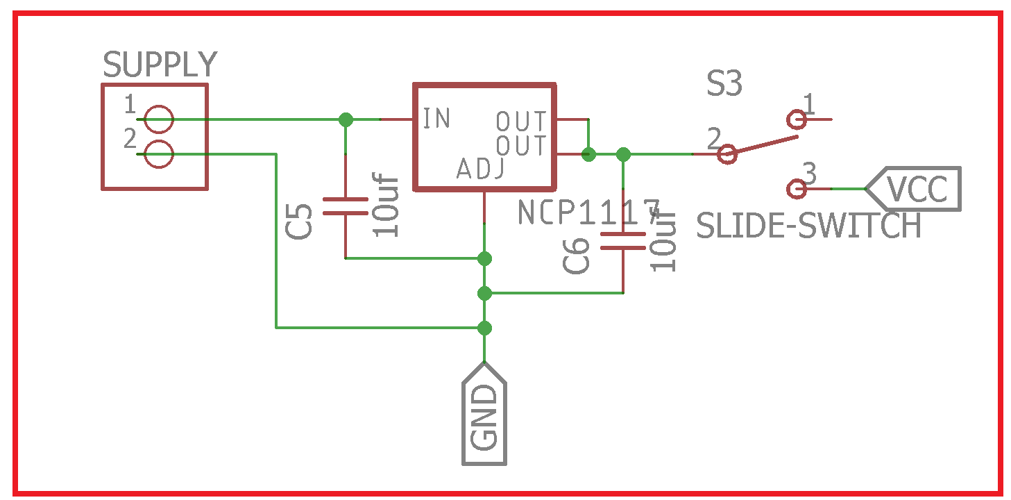
I added Slide Switch between the ESP and Voltage Regulator , so we can save power by turn off the device when it's not using .also addde 10 uf capacitor between power lines as fillters.
For HCSR04 Distance sensor we need two I/O pins , Echo and Trig. so first i used ESP8266 GPIO 9 and GPIO 10 used . after milling and loaded a sample programme i found that ESP is keep reseting automatically , and after deep googling i found that we can't use GPIO10 and GPIO9 i Arduino it will ends up in WDT (watchdog timer) resets because GPIO9 is internally used to control the flash memory. GPIO10 can be used as input only (Github issue :- https://github.com/esp8266/Arduino/issues/1446). so i re-designed the Sensor pinouts in to GPIO5 and GPIO4 and you can find more details about PCB milling in my Electronics Design week.
PCB Schematic

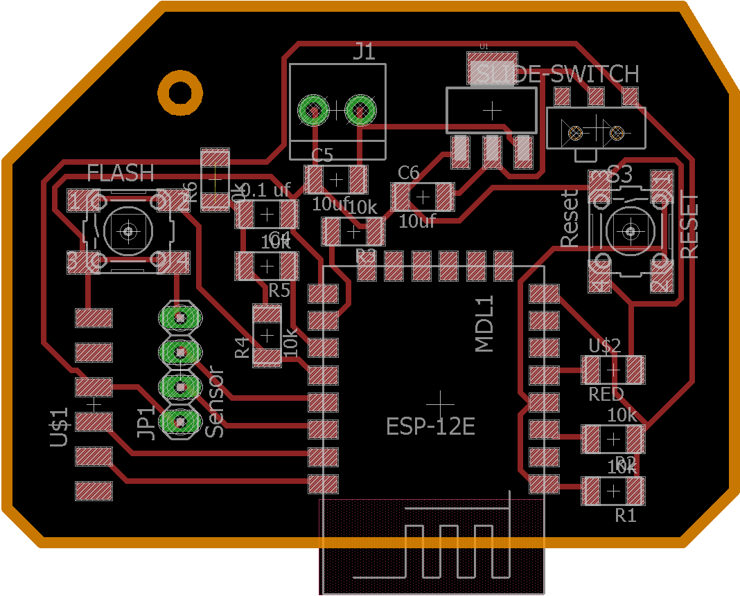
PCB Board Design
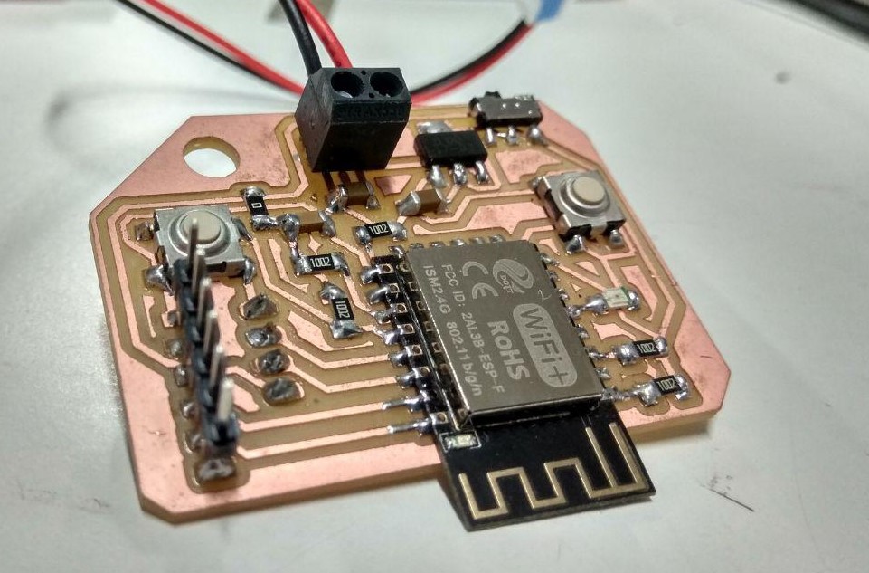
PCB milling and Soldering
I added a Screw hole to secure it with the enclosure .and i used 1/64 bit for milling and 1/32 bit for cutting and here you can find more details about PCB milling in my Electronics Production week.
Milling

Component Soldering
Bill of materials
| Sl.No | Components | Qty(Nos) | Cost per Item ₹ (INR) | Total Price |
|---|---|---|---|---|
| 1 | ESP8266-12E | 1 | 150 | 150 |
| 2 | HCSR04- Ultrasonic Sensor | 1 | 90 | 90 |
| 3 | NCP1117 3.3v - SOT223 | 1 | 20 | 20 |
| 4 | LED RED - 1206 SMD | 1 | 5 | 5 |
| 5 | Push Button - 3112P SMD | 2 | 10 | 20 |
| 6 | Slide Switch - SDPT SMD | 1 | 1 | 25 |
| 7 | Capacitor 10uf - 1206 SMD | 2 | 4 | 8 |
| 8 | Capacitor 0.1uf - 1206 SMD | 1 | 4 | 4 |
| 9 | Resistor 10k - 1206 SMD | 5 | 1 | 5 |
| 10 | Resistor 0k - 1206 SMD | 1 | 1 | 1 |
| 11 | FTDI Male Header - SMD | 1 | 10 | 10 |
| 12 | Female Pinhead 1x4 | 1 | 5 | 5 |
| 13 | Terminal 2 Pos - SMD | 1 | 10 | 10 |
| 14 | Battery 9V | 1 | 30 | 30 |
| Total Cost Of componenets in ₹ (INR) | ₹ 383 or $ 5.62 | |||
Programming
For Programming i used Arduino IDE and Arduino Corebootloader.for communication i used MQTT Protocol with ESP in-built WiFi TCP stack.
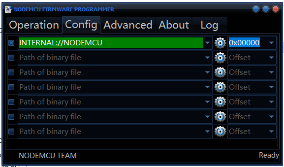
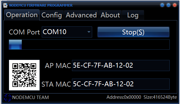
before using ESP with Arduino IDE we need to flash it with NodeMCU firmware , download the tool from nodemcu-flasher github repo. if you are using windows open the .exe file and select the Nodemcu binaray (in default it's automatically selected).then click flash.heryou go , it's done.
NodeMCU flashing Guide
You MUST set GPIO0 to LOW before programming it can be done by pressing the Flash Button on our Board
- Just click flash and you can burn firmware to ESP8266. Before you doing it,Press the Flash Button.
- Select NodeMCU Flash Binaray (in default it's automatically selected NodeMCU binary)
- And wait a moment.
- Program success.


Now we are successfully flashed NodeMCU firmware, next we are going setup the Arduino IDE to Programme the ESP8266.
Arduino IDE configuration
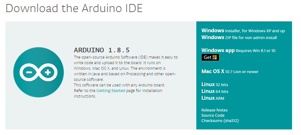
- First Install Arduino IDE (link :- https://www.arduino.cc/en/Main/Software)
- Set additional Board URL for ESP8266/NodeMCU
- In Additional Boards Manager, click add and paste the URL there:
http://arduino.esp8266.com/stable/package_esp8266com_index.jsonAnd click OK. - Download ESP8266/NodeMCU Board Definitions
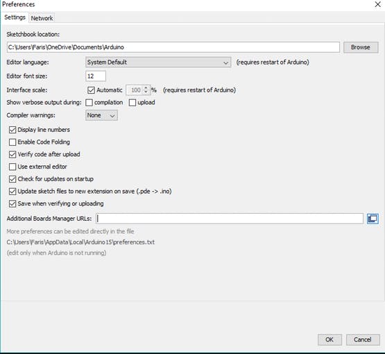
File => Preference (Ctrl + Comma)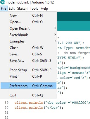

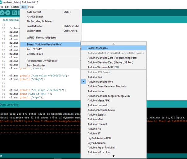
Open Board Manager by going to Tools => Board => Boards Manger.
Open Boards Manager and search for NodeMCU.
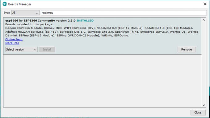
It only appears if you set the NodeMCU Board URL , Now Arduino IDE ready to programme esp8266 boards.
HCSR04 Test
Here we are try to measure Distance using HCSR04
/*
 * Salman Faris
 * HCSR04 - Test with ESP8266 Board
 */

#define trigPin D1   //Pin-14 GPIO5
#define echoPin D2   //pin-13 GPIO4

void setup() {


  Serial.begin(115200);
  pinMode(trigPin, OUTPUT);
  pinMode(echoPin, INPUT);

}


void loop() {

  long duration, distance;

  digitalWrite(trigPin, LOW);
  delayMicroseconds(2);
  digitalWrite(trigPin, HIGH);
  delayMicroseconds(10);
  digitalWrite(trigPin, LOW);
  duration = pulseIn(echoPin, HIGH);
  distance = (duration / 2) / 29.1;

  Serial.println(distance);


}
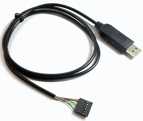
ESP8266 is need 3.3 v and morthan 3.3 voltage will damage our ESP, so for uploading code we need to use 3.3v FTDI.
To make Uploading mode we need press the Flash button and press and relese the RESET button , and It's worked without any error .
MQTT
I choosed MQTT (Message Queuing Telemetry Transport) protocol other than traditional HTTP,because it is special a machine-to-machine (M2M)/"Internet of Things" connectivity protocol. It was designed as an extremely lightweight publish/subscribe messaging transport. It is useful for connections with remote locations where a small code footprint is required and/or network bandwidth is at a premium.(link :- http://mqtt.org/).
Architecture

The publish-subscribe messaging pattern requires a message broker.so here am using Mosquitto in Microsoft Azure
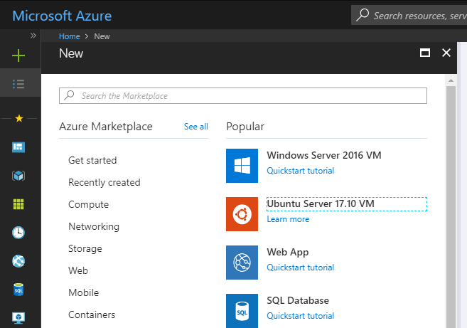
Installing Broker on Microsoft Azure
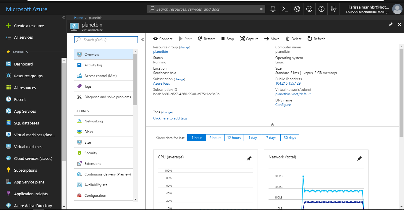
I choosed Ubuntu 17.10 as my Virtual Machine in Azure
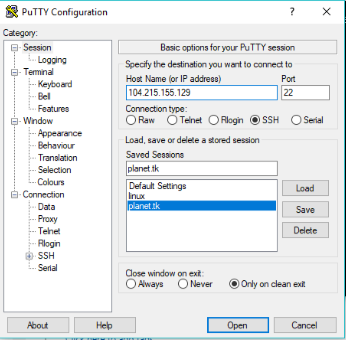
I accessed VM by SSH and i used Putty as SSH Client.
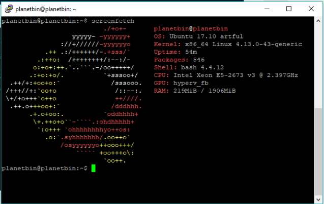
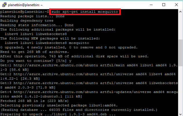
First i installed Mosquitto broker by typing sudo apt-get install mosquitto,
and i installed Mosquitto Clinet by typing
sudo apt-get install mosquitto-client.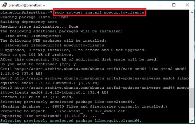
Now we are successfully installed MQTT Broker on Azure VM.next we set our Sensor Module as MQTT Subscriber .
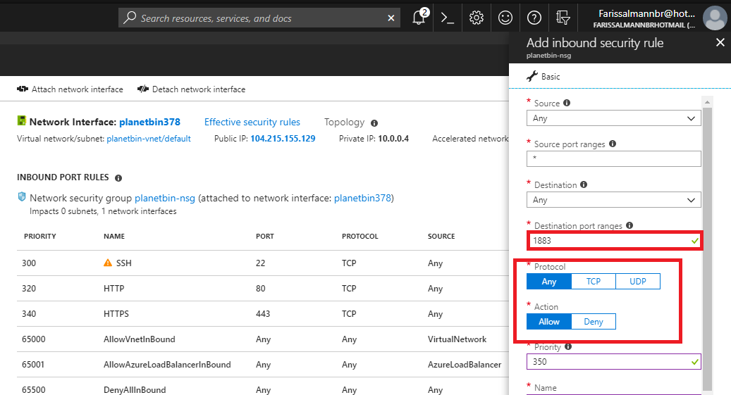
MQTT is using 1883 TCP port , so in azure we need to open the port by adding inbound security rule in Virtual Machine Network Settings.
Send data to Server
Now we are going to send Sensor data to our Azure server by using MQTT Broker, and here am using arduino PubSubClinet library (source :- https://github.com/knolleary/pubsubclient) for Publishing sensor data to server.
Sensor-node Code
/**
   Poject :- Planet Bin
   Author :- Salman Faris
   Sensor-node id :- #001
**/


#include <ESP8266WiFi.h>
#include <PubSubClient.h>


const char* ssid = "******************"; //Wifi SSID
const char* password = "*************";             //WiFi Password


const char* mqtt_server = "104.215.155.129"; //Sever IP Address

WiFiClient espClient;
PubSubClient client(espClient);

#define trigPin D1   //Pin-14 | GPIO5
#define echoPin D2   //Pin-13 | GPIO4


long now = millis();
long lastMeasure = 0;


void setup_wifi() {
  delay(10);
  // We start by connecting to a WiFi network
  Serial.println();
  Serial.print("Connecting to ");
  Serial.println(ssid);
  WiFi.begin(ssid, password);
  while (WiFi.status() != WL_CONNECTED) {
    delay(500);
    Serial.print(".");
  }
  Serial.println("");
  Serial.print("WiFi connected - ESP IP address: ");
  Serial.println(WiFi.localIP());
}


void callback(String topic, byte* message, unsigned int length) {
  Serial.print("Message arrived on topic: ");
  Serial.print(topic);
  Serial.print(". Message: ");
  String messageTemp;

  for (int i = 0; i < length; i++) {
    Serial.print((char)message[i]);
    messageTemp += (char)message[i];
  }
  Serial.println();
}

void reconnect() {
  // Loop until we're reconnected
  while (!client.connected()) {
    Serial.print("Attempting MQTT connection...");

    if (client.connect("ESP8266Client")) {
      Serial.println("connected");
      // Subscribe or resubscribe to a topic
      // You can subscribe to more topics (to control more LEDs in this example)
      client.subscribe("wastebin1");
    } else {
      Serial.print("failed, rc=");
      Serial.print(client.state());
      Serial.println(" try again in 5 seconds");
      // Wait 5 seconds before retrying
      delay(5000);
    }
  }
}


void setup() {
  Serial.begin(115200);
  setup_wifi();
  client.setServer(mqtt_server, 1883);
  client.setCallback(callback);

  pinMode(trigPin, OUTPUT);
  pinMode(echoPin, INPUT);

}
void loop() {

  if (!client.connected()) {
    reconnect();
  }
  if (!client.loop())
    client.connect("ESP8266Client");


  long duration, distance;

  digitalWrite(trigPin, LOW);
  delayMicroseconds(2);
  digitalWrite(trigPin, HIGH);
  delayMicroseconds(10);
  digitalWrite(trigPin, LOW);
  duration = pulseIn(echoPin, HIGH);
  distance = (duration / 2) / 29.1;

  Serial.println(distance);

  int data2 = 80 - distance ;

  char distance1[7];
  char data3[7];


  dtostrf(distance, 6, 2, distance1);

  dtostrf(data2, 6, 2, data3);

  client.publish("wastebin1", distance1);

  delay(500);
  client.publish("wastebin2", data3);

  delay(2000);

}
For checking i Subscribed the same MQTT topic that we used for sending the Sensor data.

Now we can see that data, that coming from the Sensor Module in our VirtualMachine Shell.but it's not a user friendly UI ,so next we are going design a dashboard with rich User Interface .
Dashboard Devlopment
We need a dashboard to display all the necessary data that come from the sensor nodes, also we need a admin panel to ensure all the thing going well. For this purpose i used Node-RED
Node-RED
Node-RED is a programming tool for wiring together hardware devices, APIs and online services in new and interesting ways.It provides a browser-based editor that makes it easy to wire together flows using the wide range of nodes in the palette that can be deployed to its runtime in a single-click.It's Great for raspid application developmnet.First i experiment with Node-RED on Raspberry PI but it's limited scope due to local network connection , so i going to run this on my Linux VM so we can monitor the data anywhere in the world .
Node-RED Installation on Azure
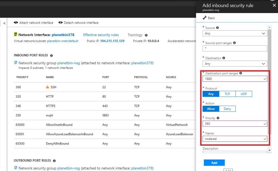
First we need to open port 1880 for Node-RED in auzre , i can done by adding inbound security rule in azure vm Network Settings.
After i installed NodeJS and NPM (Node Package Manager).it can be done by typing this commands
curl -sL https://deb.nodesource.com/setup_4.x | sudo -E bash -
sudo apt-get install -y nodejs build-essential

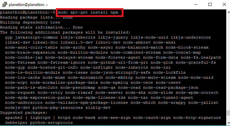
After that we can install Node-RED by typing sudo npm install -g node-red
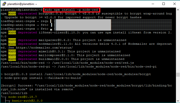
Now we successfully installed Node-RED, let's check it run the node-red by typing node-red after that you can see that node-red running in the shell.
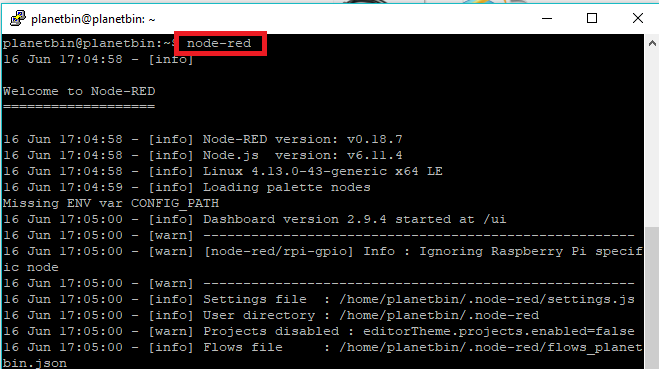
to view the Node-RED dashbord , open browser and go to http://ip-address:1880 , replace the ip address ,
in my case it's http://104.215.155.129:1880/
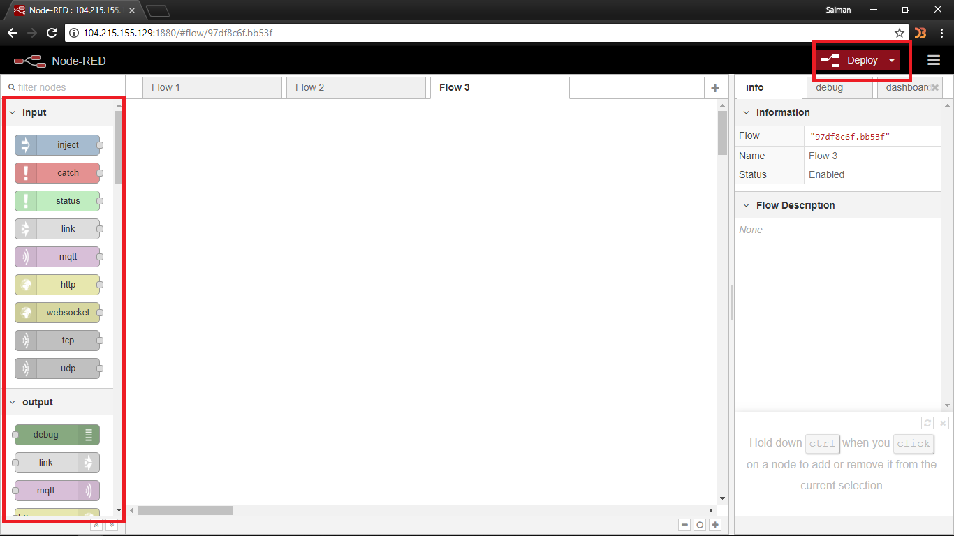
In the left you can see the Nodes section and in the middile is the Flow Screen
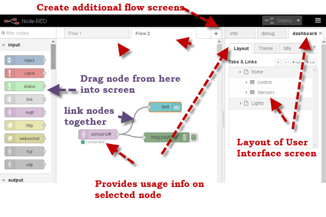
Next we need to setup appropriate nodes based what we need.so here we are using MQTT so first we are going to add , MQTT and after we are setting the appropriate node-pallets
here you can see how i added the pallets into the dashboard .
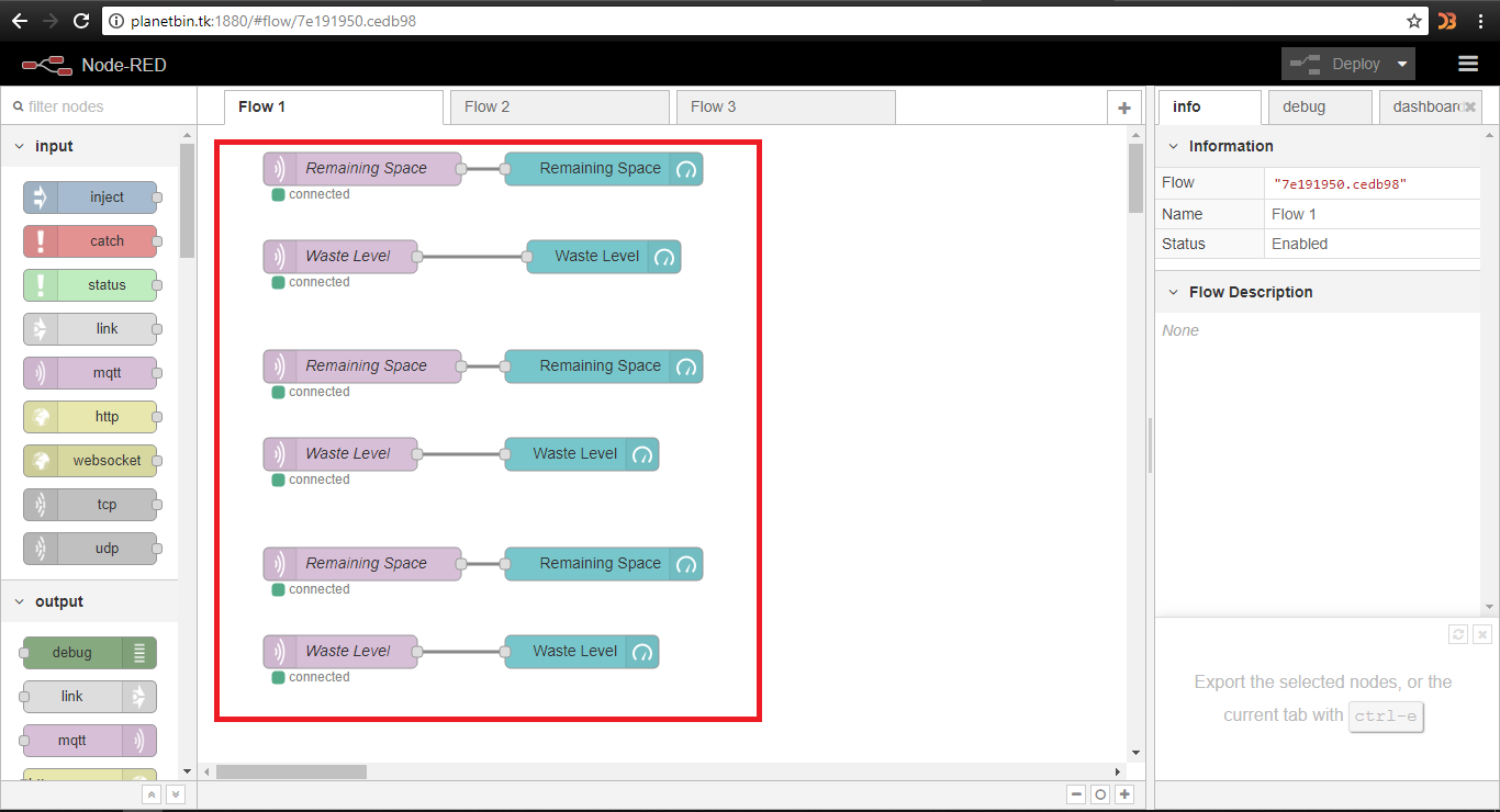
Planetbin.tk domain
I used Server IP address in-order to work with node-red , now i just adding the custom domain in my server.i used Freenomto get my custom domainand DNS , it's free of cost for one year .

Now we can access dashboard using Planetbin.tk from anywhere
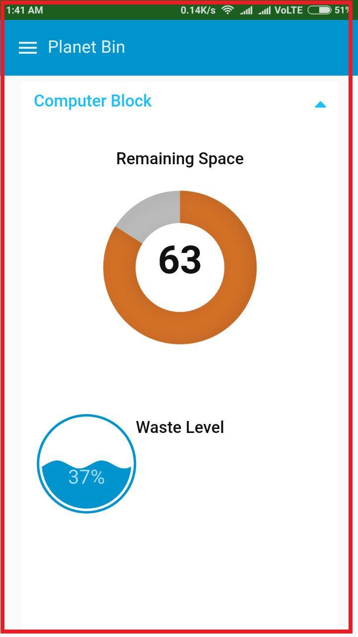
User Interface Design
I just builded a basic UI using Node-RED-Dashbord pallets.

Mobile App
I devloped Android App for clinet users ,it's based on the webview of Node-RED Dashboard.
PlanetBin.tk Project Website
I Devloped a Website for my Final Prject and hosted in the Azure Linux VM.I used simple html and CSS to build this website and I also referred an open source free template to build the site.

3D Enclosure Designing
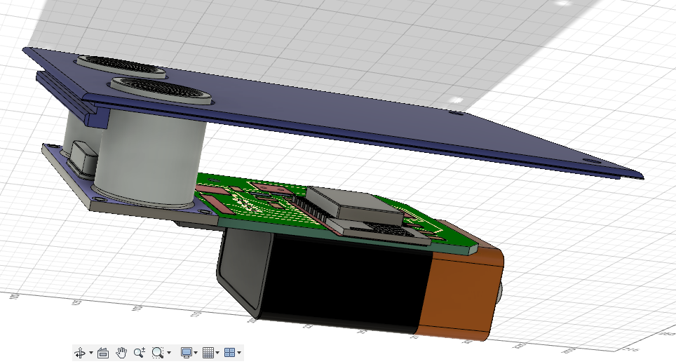
Our Software side is now completed , now we need a Enclosure for the Sensor node. so my plan is to 3D print the case , so i staretd to design Enclosure in Fusion360.First i created a 3D Design of PCB and component using Eagle Fusion Sync .and I also exported the ultrasonic and 9V battery 3D model from GrabCAD.then is joind all the models with my pcb as like the real module.you can refer my 3D SCANNING AND PRINTING week documentation .
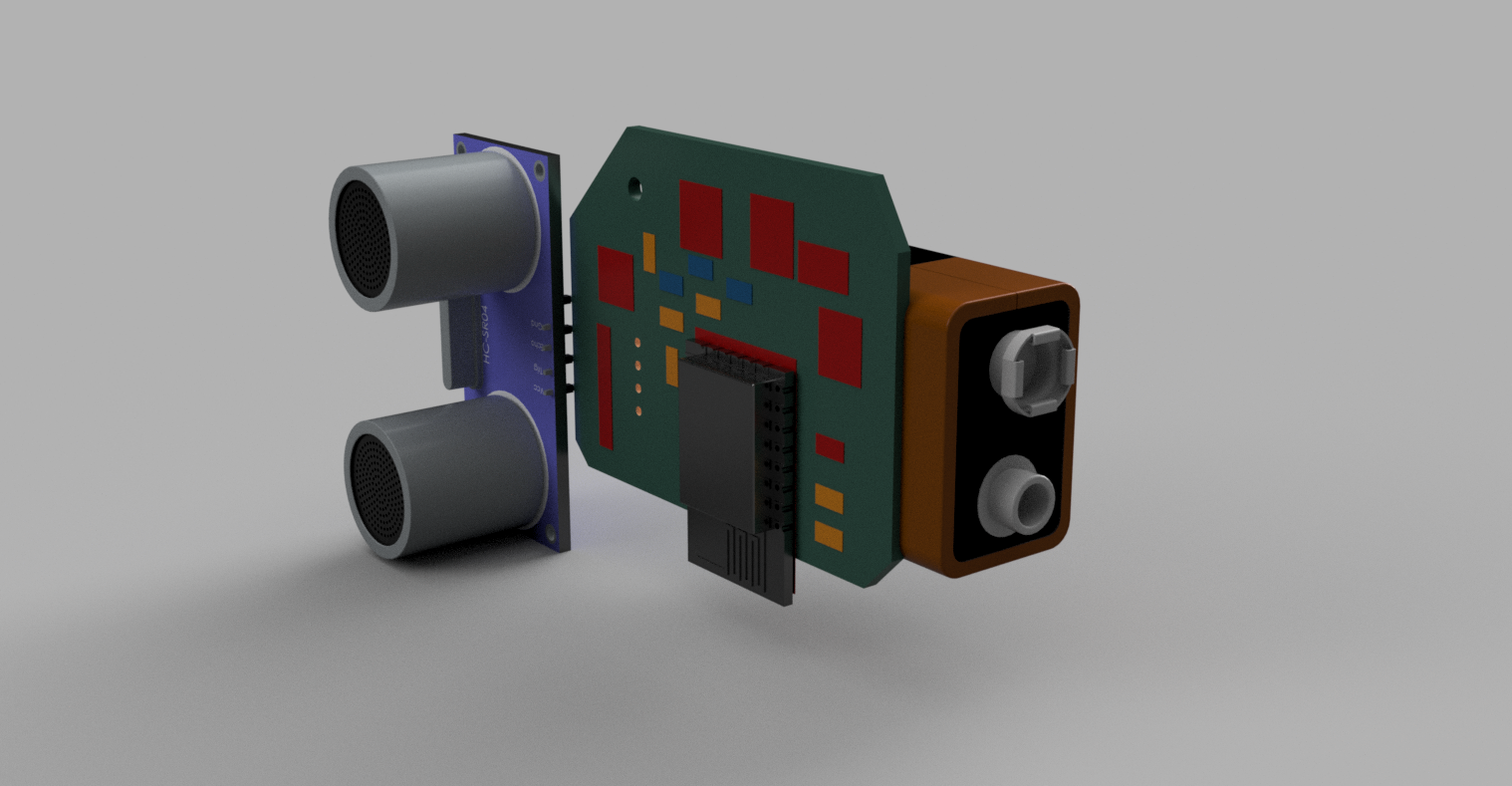
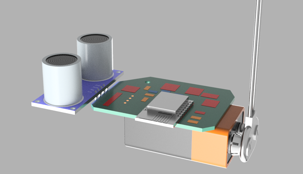
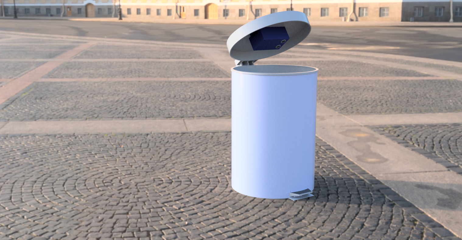
This is a how it's looks after rendering .i used Fusion360 for rendering this. now we have the 3D Design of our Sensor Module , so now we can easly make the enclosure based the module reference.First I imported the 9V Battery holder from GrabCad .

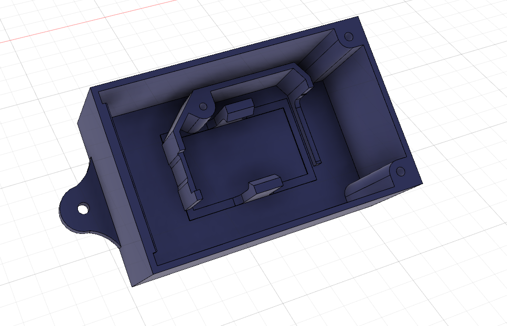
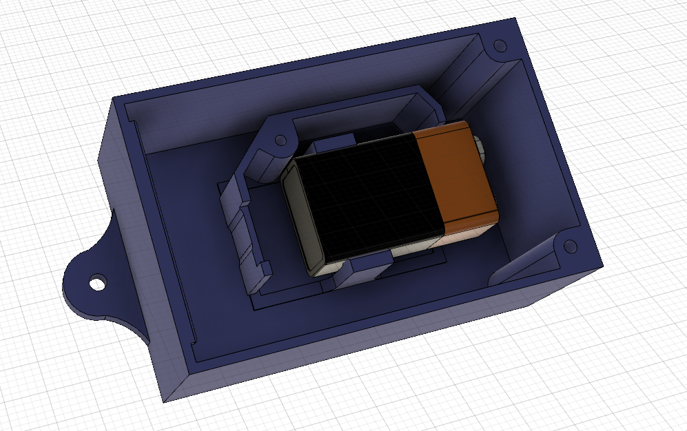
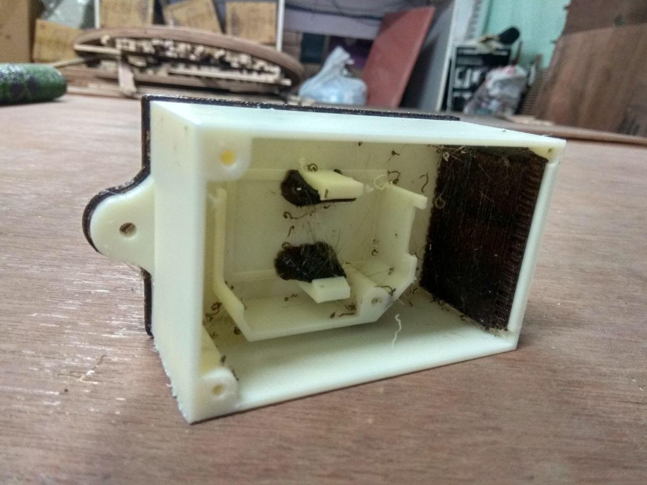
After that I Creatd a Bottom Enclosure based on the battery holder.and also added screw hols at this bottom part so we can mount it on wastebin .I just putted the 9v battery in to the enclosure to make sure everything is working perfect .and I also mounted Sensor Module on the Enclosure , so we can also check the size of the box and holes correctly.
This is acutally help me in give a space for the 9v battery clip , in my first design it not fit becasue of the 9v battery Clip is stuck,so first i added the battery clip 3D Design and expanded the Enclosure a little bit. actually Fusion Sync was very helpfull when it's comes to production like this.
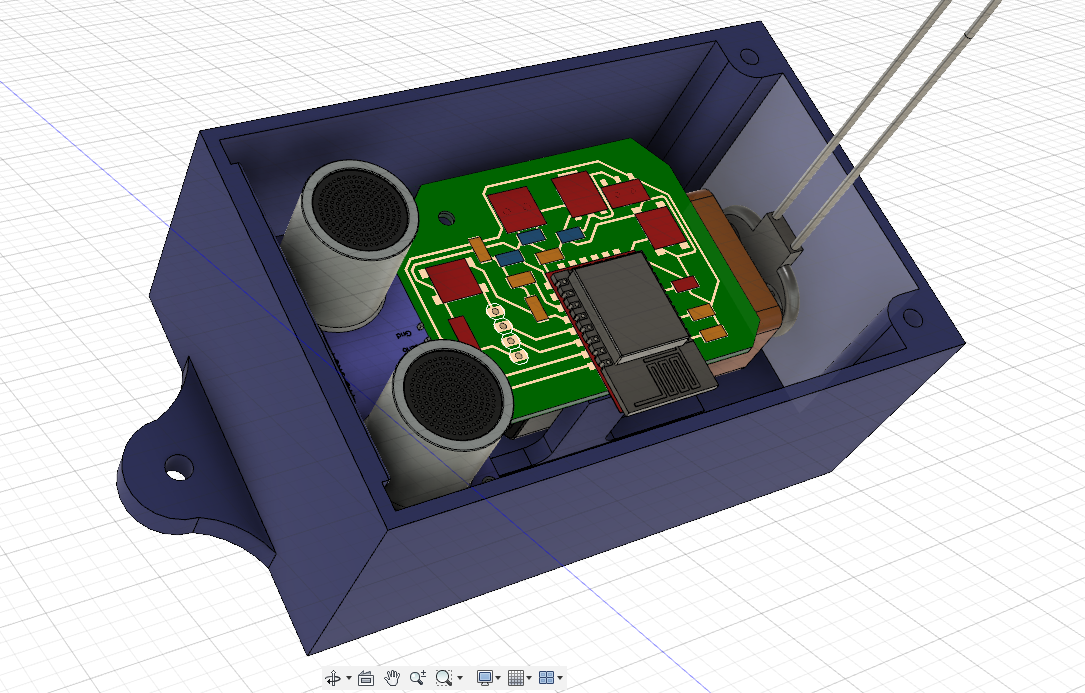
After the main base design , I designed the top part with reference of Ultrasonic sensor .add two hole for the ultrasonic sensor .

I added a mounting part in Top and Base for other side i used screw holes , that means i only need to use two screw to secure the top part and base part.

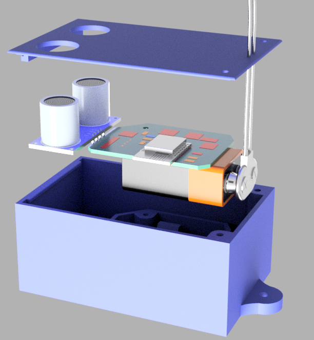
This is my completed Enclosure with PCB added inside.
Exploded View
3D Design Video log
Rendered Image
3D Printing
I exported the 3D designes as STL file for 3D printing .I used Dimension 3D printer , it using ABS Fillament .for slicing i used catalystEX software.
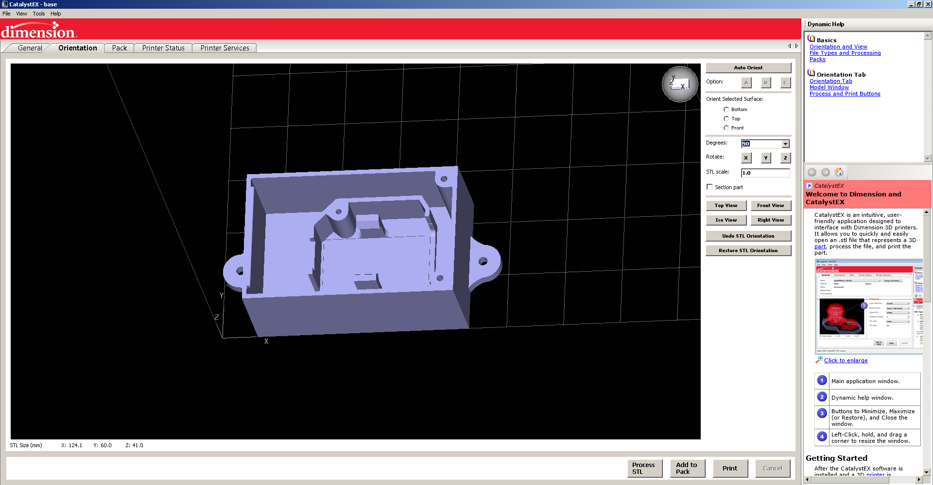
It's took almost 7 hours to print the both parts , after printing we need to remove the support matrial using the support removel solution.

It took 4 hours to melt the support matrial from the model.after that I tested with 9v battery to check everything working great.also tried with the PCB and it's fitted perfectly.


3D Printed Enclosure

vinyl printing
Next I did the vinyl printing on the top of the 3D model .I used Inkscape to draw the Text and Logo.for more details about the Vinyl cutting you can refer my COMPUTER-AIDED DESIGN week documentation .I used Roland CAMM1-Servo Vinaly cutter to do this job.
I cutted PLANETBIN.TK name, due to large font I removed the .tk part , after the sticker cutting I placed it on the 3D Model using a Masking tape.
Vinyl Sticker
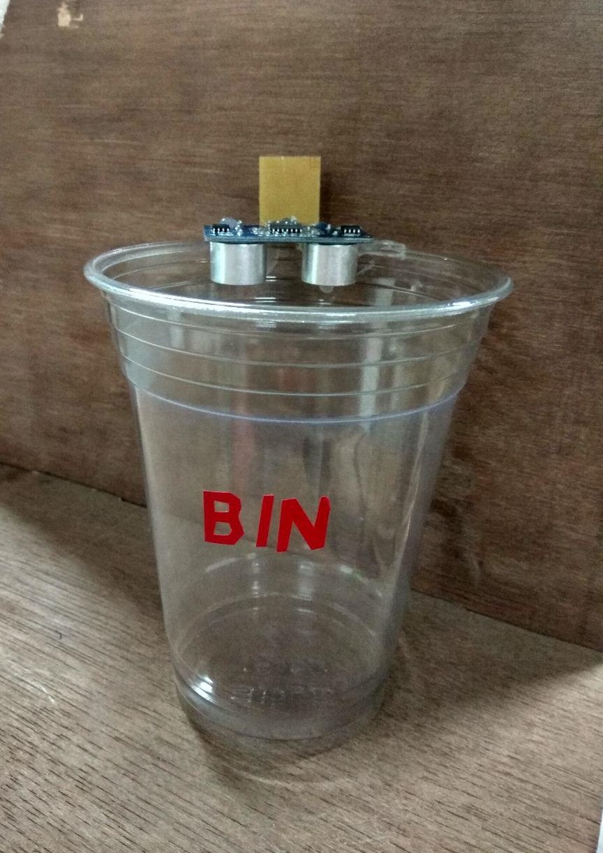
installation
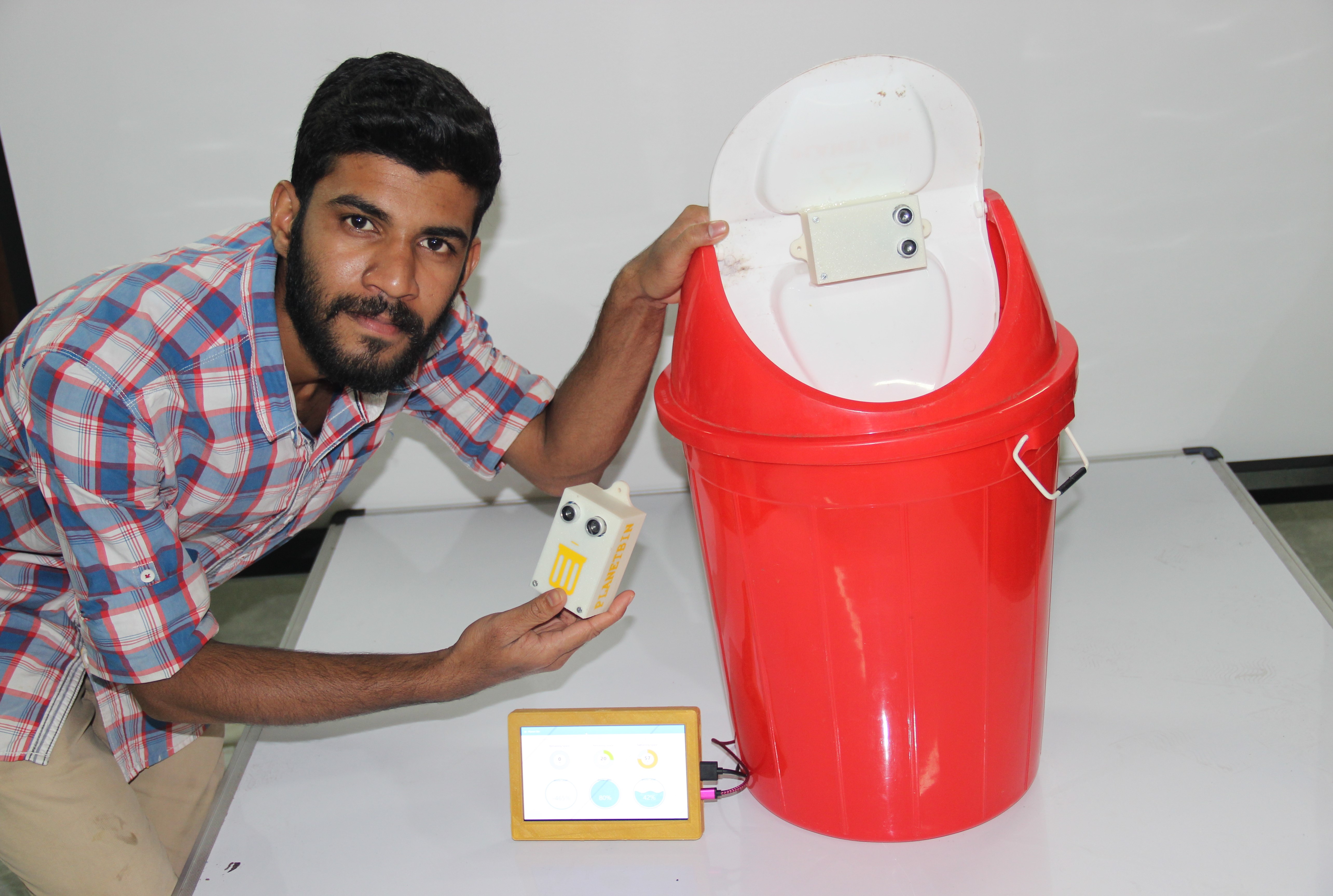
Now we need to install the Smart waste bin module into a waste bin ,I used a normall wastebin that found in top of our lab building .I used hot glue gun to secure the wastebin top and our sensor module .before installing we need to manually turn on the sensor node using the Slide Switch moving esp side .

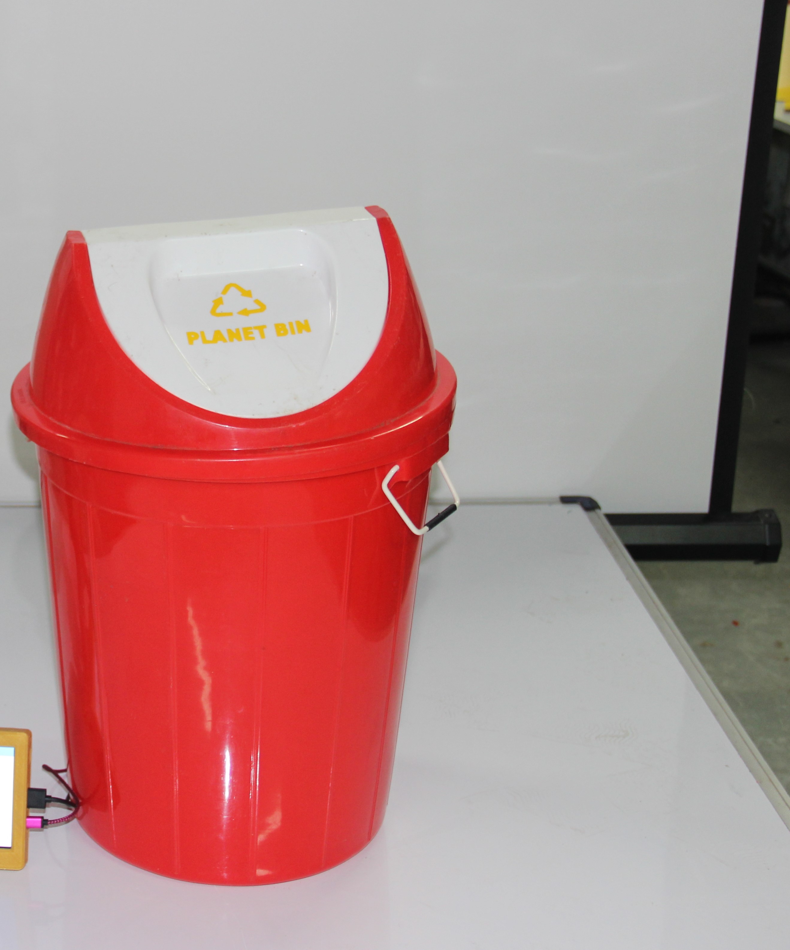
I used vinyl printing to the sticker work on the WasteBin.For the dashboard I also created small Dashboard system for drivers to disply the waste level and optimized path.Here I used a Raspberry Pi with 7-inch LCD Display to do this.

Here i displying the WasteBin Status and WasteBin Location . by using a Rpi , but due to voltage problem I also used my computer video output.
Hero Shot
Presentation Video