Week 9. embedded programming
Assignment
- group project: experiment with other architectures
- individual project: read a microcontroller data sheet program your board to do something, with as many different programming languages and programming environments as possible
group assignment
see FabLab Kamakura's group assignment page.
read datasheet
I read through the ATtiny44 datasheet and picked out sections which interested me and are essential for programming.
First, on the cover, Features. Speed depends on the voltage.

Pin configuration. The number of pin A is bigger than that of pin B.
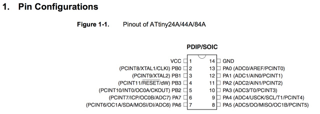
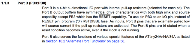
Why the explanation of PORT B come first?
Port B is a 4-bit bi-directional I/O port with internal pull-up resistors.
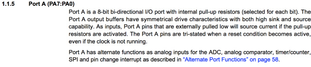
Port A is an 8-bit bi-directional I/O port with internal pull-up resistors. It also has alternate analog inputs, which Port B doesn't
Default Clock Source. CKDIV8 fuse was programmed, which means the system clock was divided by 8. The power consumption is proportional to the internal system clock.

Fuse Low Byte. It is related to the system clock. As I mentioned earlier, CKDIV is programmed (the value is 0).

program my board to do something
I tried to code with two programming languages, avr-gcc(C language) and Arduino.
avr-gcc
blinking LED
I tried to code blinking an LED. I saw through a lot of code and was freaked out because there were various bitwise operation methods. First, I tried a binary method which is familiar to me.
Binary
#include <avr/io.h>
#include <util/delay.h>
#define F_CPU 2500000

int main() {
	DDRB = 0b00000100; //PB2 as output
	while(1) { 				//endless loop
		PORTB = 0b00000100; //LED ON
		_delay_ms(1000);    // wait for 1000 ms
		PORTB = 0b00000000; //LED off
		_delay_ms(1000);    //wait for 1000 ms
	}
	return 0;
}
Folloing bitwise methods works same. I show only code in main function.
hexadecimal
	DDRB = 0x04; //PB2 as output
	while(1) { 				//loop
		PORTB = 0x04;     //LED on
		_delay_ms(1000);    //wait for 1000 ms
		PORTB = 0x00; //LED off
		_delay_ms(1000);    //wait for 1000 ms
	}
macro
	DDRB = _BV(PB2); //PB2 as output
	while(1) { 				//loop
		PORTB  = _BV(PB2); //LED on
		_delay_ms(500);    //wait for 1000 ms
		PORTB ^= _BV(PB2); //LED off
		_delay_ms(500);    //wait for 1000 ms
	}
left shft bit operator
DDRB |= (1 << PB2); PB2 as output
while(1) { 				//loop
		PORTB  |= (1 << PB2); //LED on
		_delay_ms(2000);    //wait for 1000 ms
		PORTB &= ~(1 << PB2); //LED off
		_delay_ms(2000);    //wait for 1000 ms
	}
left shift bit and XOR operator, which can reduce the code lines.
DDRB |= (1 << PB2); //PB2 as output
while(1) { 				//loop
		PORTB  ^= (1 << PB2); //LED on and off
		_delay_ms(1000);    //wait for 1000 ms
		}
problems
As I set the delay time in 1000 ms, I thought a LED would blink like a clock, but it didn't. The time interval of blink was (nearly?) 8 times longer than the period it should be.
As Daisuke mentioned in his assignment, this problem arose from the CKDIV8 fuse. He resolved it using Atmel Studio 7 which was only available for Windows.
So, I tried to avoid this obstacle in another way. I realized that the F_CPU value was defined and its value was 20000000(20 MHz) in original Neil's makefile. It goes like this.
PROJECT=XXXXXX
SOURCES=$(PROJECT).c
MMCU=attiny44
F_CPU = 20000000
I divided the F_CPU value by 8, 2500000 as CKDIV8 remained programmed. And the result was just what I expected!!
Smaller F_CPU value made an LED blinking faster.
I have to write F_CPU definition in both .c and .make file to get a reproducible result. I don't fully understand the reason.
F_CPU = 20,000,000
F_CPU = 2,500,000
F_CPU = 500,000
LED ON with button
I tried to write a program that a LED would on when I push a button.
#include <avr/io.h>
#include <util/delay.h>
#define F_CPU 2500000

int main() {
    DDRB |= (1 << PB2);
    PINA |= (1 << PA7);

	while(1) { 	//loop
		if (PINA&(1 << PA7)) // check PA7 state high or low
        PORTB  |= (1 << PB2); // set bit
        else
		PORTB &= ~(1 << PB2); // clear bit
		//_delay_ms(2000);    //wait for 1000 ms
	}
	return 0;
}
why?
I have believed that I push a button and the pin connected to the button would be high. After writing a program to ATtiny44'S EEPROM, LED became ON state without being pressed the button.
Why?
In the datasheet, a PORT was pulled up. So, when the button was pressed, and PINA7 was grounded, then PINA7 was set to LOW, which means, in my program, PB2 would be set to LOW. When the button was pressed, LED would be off.
I switched commands in if/else statement and I got a reasonable response.
#include <avr/io.h>
#include <util/delay.h>
#define F_CPU 2500000

int main() {
    DDRB |= (1 << PB2);
    PINA |= (1 << PA7);

	while(1) { 	//loop
		if (PINA&(1 << PA7)) // if PA7 is high(button not pressed)
        PORTB  &= ~(1 << PB2); // set bit
        else
		PORTB |= (1 << PB2); // clear bit
		//_delay_ms(2000);    //wait for 1000 ms
	}
	return 0;
}
arduino
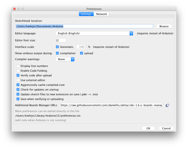
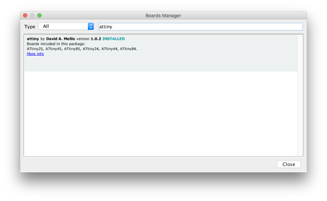
Before using ATtiny from Arduino, I have to install ATtiny board support. I installed it following this instruction.
In Arduino IDE, "Arduino > Preferences..." Add the link, "https://raw.githubusercontent.com/damellis/attiny/ide-1.6.x-boards-manager/package_damellis_attiny_index.json" in Additional Boards Manager URLs box.
press install button.
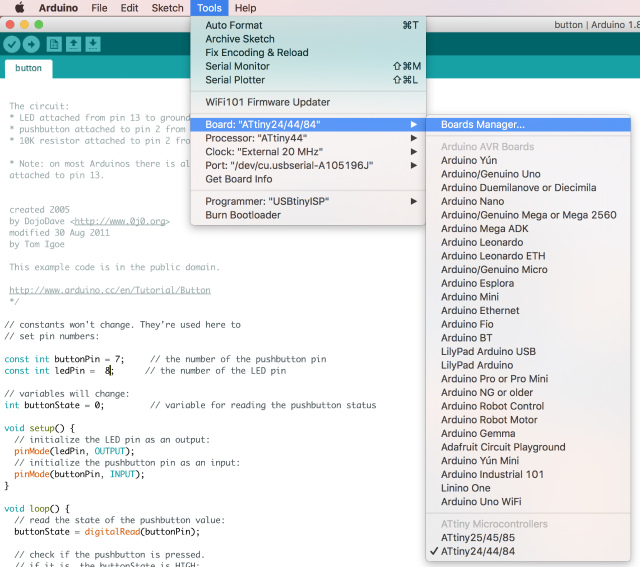
Then, select following settings.
from "Tools > Boards:", select "ATtiny24/44/84"
from "Tools > Processor:", select "ATtiny44"
from "Tools > Clock", select "External 20 MHz"
from "Tools > Port", select a proper option depending on your device
then, "Tools > Burn Bootloader"
Now, I'm ready for using ATtiny from Arduino.
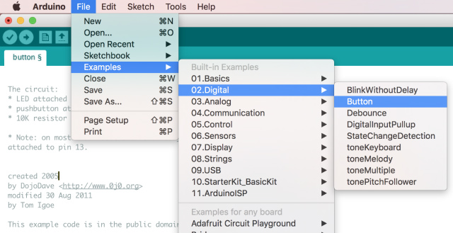
Open a sketch, "Button" from "File > Examples > 02.Digital > Button."
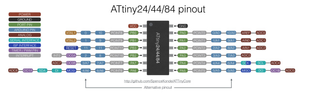
I checked the pin mapping ATtiny PA7(connected to a button) and PB2(connected to an LED) to Arduino. It was pin 7 and 8, respectively.
Then, I compiled and uploaded the sketch. The result was following.