Week9 : Embedded Programming
Embedded Programming
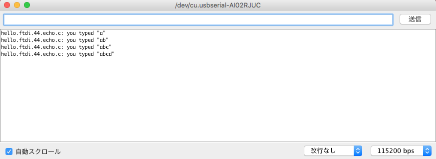
Check Serial Communication
To check Echo Hello-World Board, I tried with Arduino IDE. (actually I tried with python file term.py in week07)
-

Step1:
Open Preferences [Arduino]->[Preferences] -
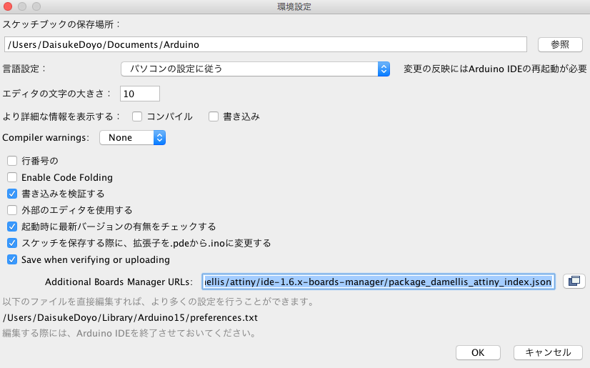
Step2:
Input "https://raw.githubusercontent.com/damellis/attiny/ide-1.6.x-boards-manager/package_damellis_attiny_index.json" to [Additional Boards Manager URLs] -

Step3:
[Tool]->[Board Manager]
-
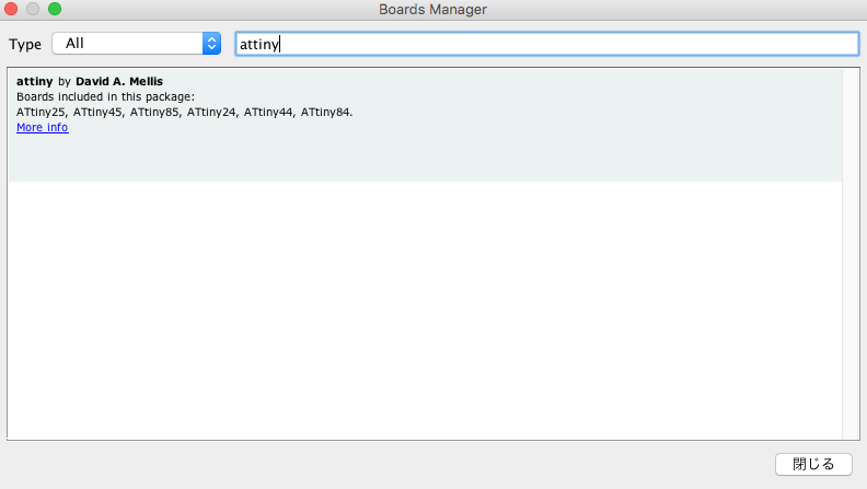
Step4:
Input "attiny" to search attiny -

Step5:
Select attiny by "David A. Mellis" and [install] -
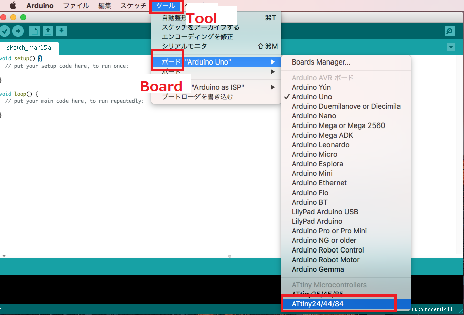
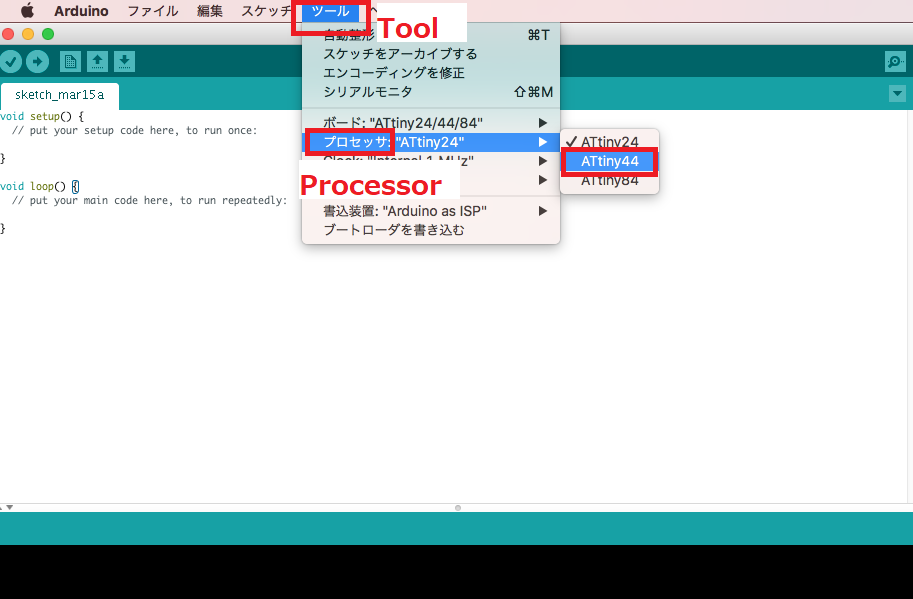
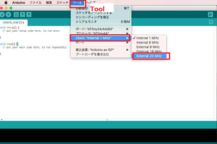
Step6:
[Tools]->[ATtiny24/44/84]

Programming & Datasheet
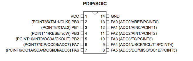
I learned roles of each pins and fuse settings from datasheet as below. Datasheet is too long to understand. I feel that I should learn more about electrical characteristics and setting of fuse.
LED with C
【LED blink】
I made LED blink program with C. I read Neil's program. Programs using hexadecimal numbers were difficult for me, so I first write a program using binary numbers.
burn to boad
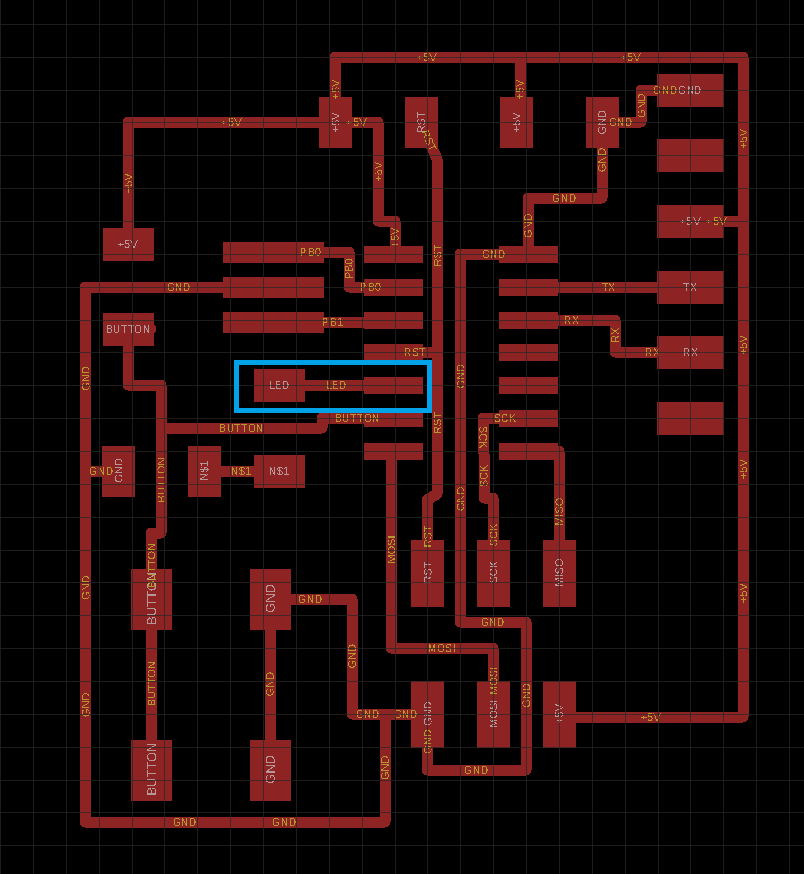
As datasheet shows, I connected LED to PB2 pin.
【Problem: 8 times longer】
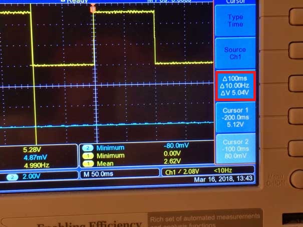
I set delaytime to 100ms. But as the movie shows, the interval looks like 1000ms(1s). Then, I set delaytime to 1000ms and measured the interval time with stopwatch. It was about 8 seconds. (About 16 seconds in the case of 2000ms)
In other words, it took eight times longer.
Just to be sure, measuring with an oscilloscope, it took exactly 8 times longer.
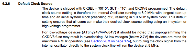
When I checked with the instructor and Fab Lab staff, we found that the data sheet has the following description.Initial timer clock is set to divided by 8. It means timer counter will be 8 times longer. So, I had to rewite fuse.
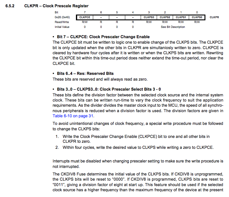
When rewriting fuse, I use Atmel Studio.Uncheck LOW.CKDIV8, CLKPS had been rewritten.
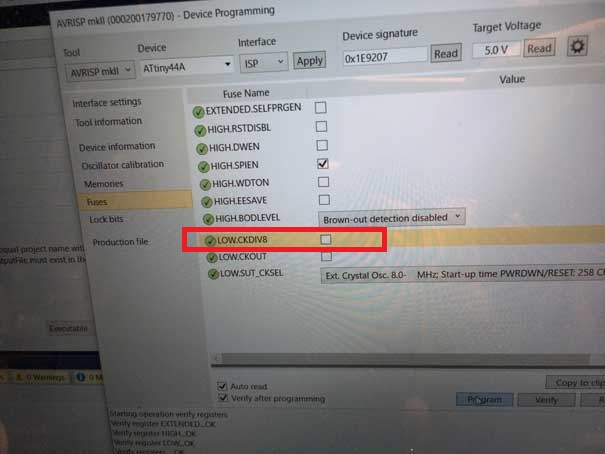
Finally, interval had become 100ms !
【button & LED】
Next, I tried to make LED ON-OFF button program using hexadecimal.
In this circuit, if the button is pushed, PA7 receive LOW(0) signal.

if the button is not pushed, PA7 receive LOW(1) signal.
It worked well.
I made LED blink program with C. I read Neil's program. Programs using hexadecimal numbers were difficult for me, so I first write a program using binary numbers.
#include <avr/io.h>
#include <util/delay.h>


int main(void) {
    DDRB = 0b0100; //PB2 output(1) PB0,1,3input(0)
    while (1) {
        PORTB = 0b0100; //PB2High
        _delay_ms(100);    //wait 100ms
        PORTB = 0b0000; //PB2Low
        _delay_ms(100);    //wait 100ms
    }
}
$ make -f led.c.make
$ sudo make -f led.c.make program-usbtiny-fuses
$ sudo make -f led.c.make program-usbtiny
$ sudo make -f led.c.make program-usbtiny-fuses
$ sudo make -f led.c.make program-usbtiny
As datasheet shows, I connected LED to PB2 pin.
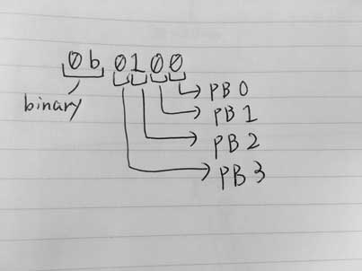
DDRB , PORTB
B of the last character of DDRB,PORTB corresponds to P"B". (If you use PA pin you have to wirte DDRA, PORTA)
DDRB = 0b0100;
This sentense means PB2 set as output(1) pin and PB0,PB1,PB3 as input(0) pin.
【Problem: 8 times longer】
I set delaytime to 100ms. But as the movie shows, the interval looks like 1000ms(1s). Then, I set delaytime to 1000ms and measured the interval time with stopwatch. It was about 8 seconds. (About 16 seconds in the case of 2000ms)
In other words, it took eight times longer.
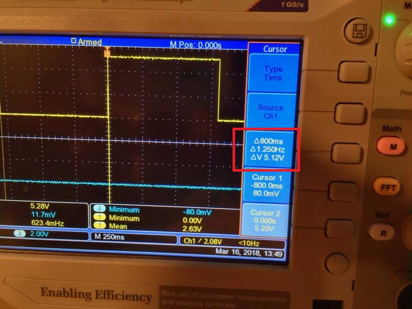
Just to be sure, measuring with an oscilloscope, it took exactly 8 times longer.
When I checked with the instructor and Fab Lab staff, we found that the data sheet has the following description.Initial timer clock is set to divided by 8. It means timer counter will be 8 times longer. So, I had to rewite fuse.
When rewriting fuse, I use Atmel Studio.Uncheck LOW.CKDIV8, CLKPS had been rewritten.
Finally, interval had become 100ms !
【button & LED】
Next, I tried to make LED ON-OFF button program using hexadecimal.
#include <avr/io.h>
#include <util/delay.h>
#include <avr/io.h>

int main(void) {
    DDRB = (1<<PB2);//0b0100; //PB2 output(1) PB0,1,3input(0)
    DDRA = 0x0;//0b00000000; //PA7 input(0) PB0-6 input(0)too
    while (1) {
        if ((~PINA & (1<<PA7)) ==  (1<<PA7))// if (!(PINA & (1<<PA7))) is same meaning
        {
            PORTB = (1<<PB2);//0b0100; //PB2High
        } else {
            PORTB = ~(1<<PB2);//0b0000; //PB2Low
        }
    }
}
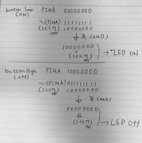
PINA is 00000000
if the button is not pushed, PA7 receive LOW(1) signal.
PINA is 10000000
I intend to the LED to shine when I pressed the button.It means
if PINA is 00000000 then LED will be shine
~(tilde) is a bit invert operator.
~(1000) means 0111
<< is an operator that shifts bits to the left. x << n means shifting x left by n bits.
1<<3 means 1000
Following portion is complex.
if ((~PINA & (1<< PA7)) == (1<< PA7))
The following picture shows the above conditions.It worked well.
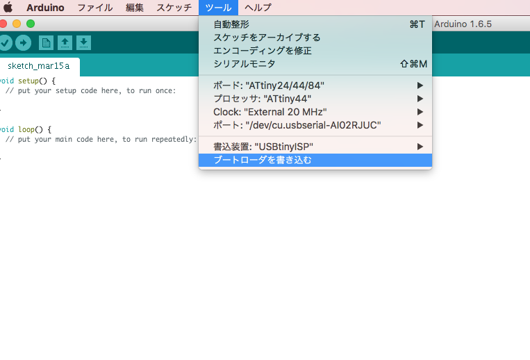
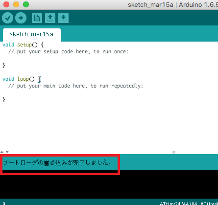
LED with Arduino
Next, I tried Arduino environment. To use Attiny44A as arduino, we have to write the boot loader first.
Acording to following correspondence tabel, PB2 is pin8, PA7 is pin7 in Arduino.
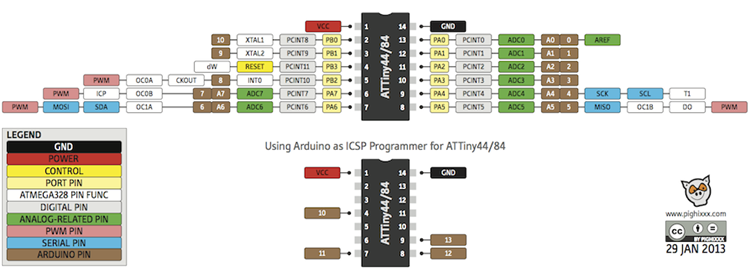
http://42bots.com/tutorials/programming-attiny84-attiny44-with-arduino-uno/
I wrote following program with Arduino. It is simple and more easier to understand than C.

http://42bots.com/tutorials/programming-attiny84-attiny44-with-arduino-uno/
I wrote following program with Arduino. It is simple and more easier to understand than C.
const int ledPin=8;
const int buttonPin=7;

void setup() {
  // put your setup code here, to run once:
  pinMode(ledPin,OUTPUT);
  pinMode(buttonPin,INPUT);

}

void loop() {
  // put your main code here, to run repeatedly:
  int button;

  button=digitalRead(buttonPin);

  if(button==LOW){
    digitalWrite(ledPin,HIGH);
  }else{
    digitalWrite(ledPin,LOW);
  }
}
Files
Programming file is here.
Group assignment
We triedd RaspberryPi(ARM) and micro:bit(nRF51822). Group assignment is here.