1.Making My WIFI
I started this week by my WiFi module ESP8266mod
The ESP8266 WiFi Module is a self contained system-on-a-chip (SOC) with integrated TCP/IP protocol stack that can give any microcontroller access to your WiFi network. The ESP8266 is capable of either hosting an application or offloading all Wi-Fi networking functions from another application processor. Each ESP8266 module comes pre-programmed with an AT command set firmware, meaning, you can simply hook this up to my Atmega board or Arduino device and get about as much WiFi-ability as a WiFi Shield offers
To make my WiFi board I needed this components:
1. ESP8266mod
2. The LM1117 which is a series of low dropout voltage regulators with a dropout of 1.2V at 800mA of load current. It has the same pin-out as National Semiconductor's industry standard LM317. The LM1117 is available in an adjustable version, which can set the output voltage from 1.25V to 13.8V with only two external resistors.
3. One capacitor 1mf
4. One capacitor 10mf
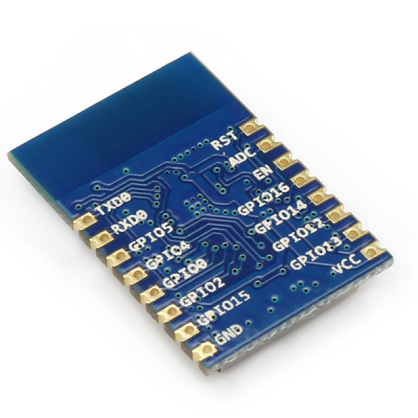
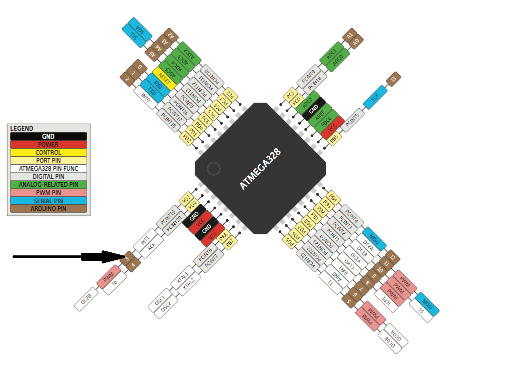
Here is the pin out
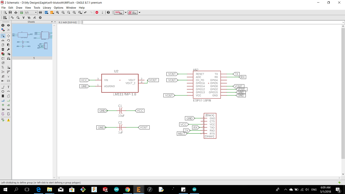
And this is the schematics of my board
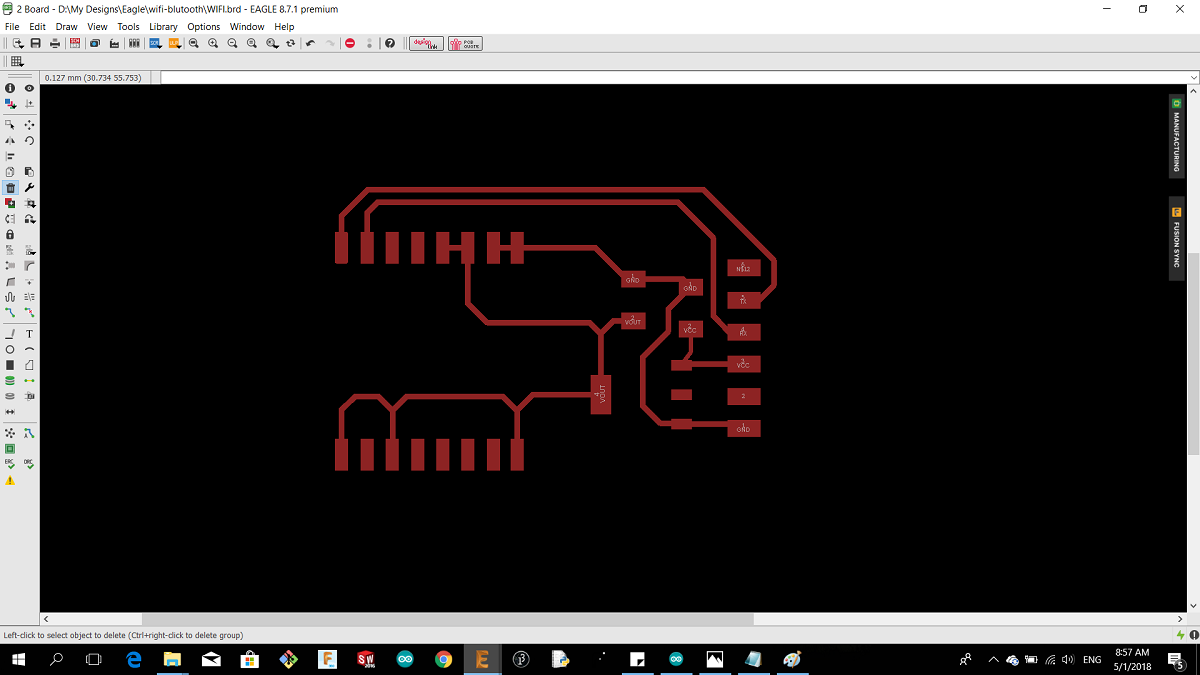
and the board layout
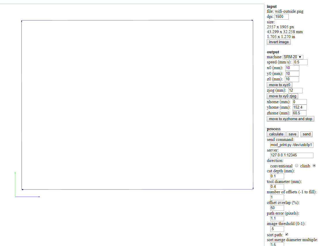
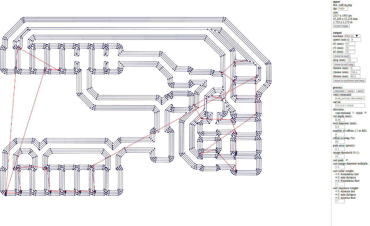
I used Fabmodules to generate the tool bath, I used roland srm-20
this is the outside cut
and this is for the inside cut
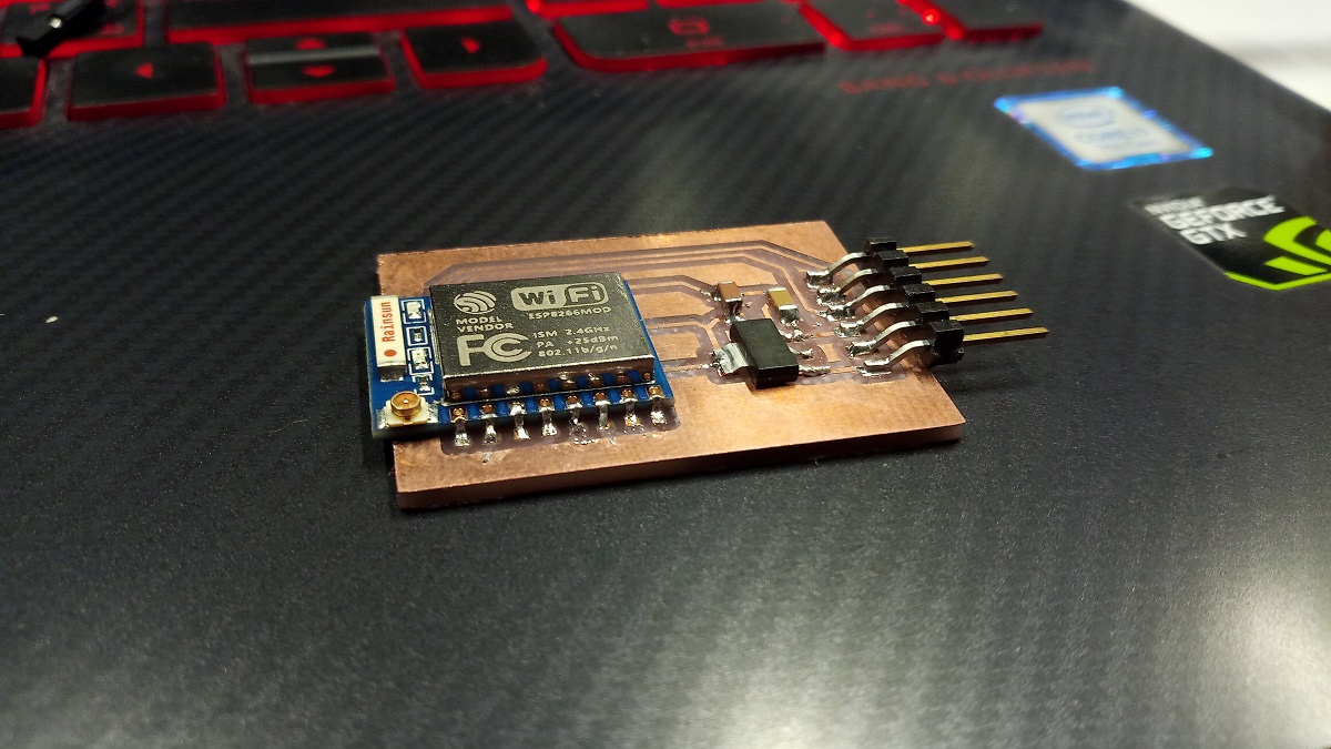
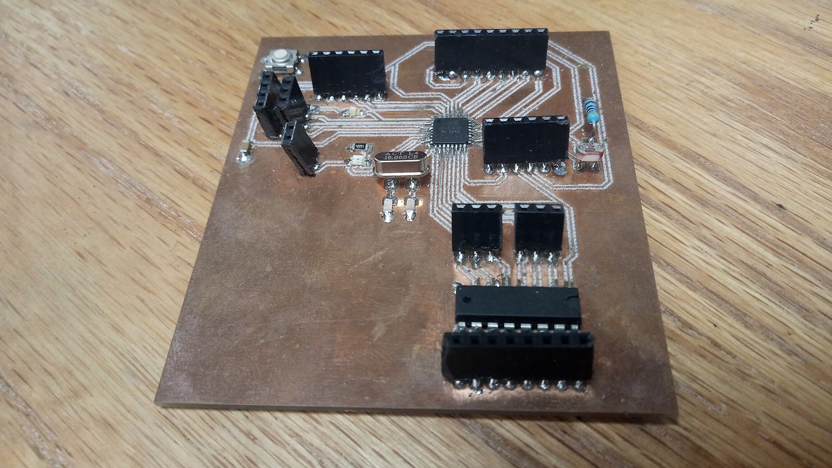
and this is my board after soldering
I read more about the ESP from this Link so I knew that the votage of the wifi chip 3.3 volt
I installedthe FTDI drive from this LINK to connect the the ESP whith the FTDI cable
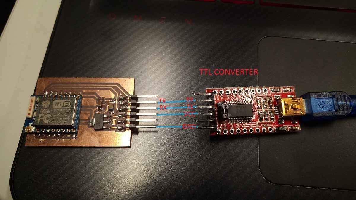
And I used the TTL converter because the ESP should working in 3.3 volt and the pc has 5 volt .
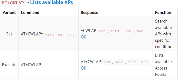
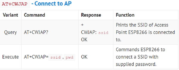
I start reading and playing with AT commands and this is a link for good Tutorial for AT commands
Now I connected the TTL converter with the ESP
3.3V FTDI cable connects to the GND and VCC of the board
FTDI cable TX ESP8266 board TX
FTDI cable RX ESP8266 board RX
Then I used Arduino serial monitor for AT commands

AT


OK
AT+CWLAP

+CWLAP:(3,"Moto M",-52,"66:db:43:93:d3:68",1,10,0)
+CWLAP:(3,"Luminus Incepto",-73,"d4:2c:44:dd:3e:20",1,6,0)
+CWLAP:(3,"Luminus_Guests",-72,"d4:2c:44:dd:3e:21",1,6,0)
+CWLAP:(3,"Luminus Incepto",-79,"d4:2c:44:dd:54:20",1,-7,0)
+CWLAP:(3,"Luminus_Guests",-79,"d4:2c:44:dd:54:21",1,-7,0)
+CWLAP:(3,"Luminus Incepto",-72,"d4:2c:44:dd:59:20",6,10,0)
+CWLAP:(3,"Luminus_Guests",-66,"d4:2c:44:dd:59:21",6,10,0)
+CWLAP:(3,"Luminus Incepto",-71,"d4:2c:44:dd:4f:a0",11,16,0)
+CWLAP:(3,"Luminus_Guests",-72,"d4:2c:44:dd:4f:a1",11,16,0)
+CWLAP:(0,"ZAIN-ZINC",-80,"70:3a:0e:d9:0d:e0",11,-12,0)
+CWLAP:(3,"Luminus Incepto",-76,"d4:2c:44:dd:52:80",11,11,0)
+CWLAP:(3,"Luminus_Guests",-78,"d4:2c:44:dd:52:81",11,10,0)

OK
AT+CWJAP="Moto M","sogusogu"

WIFI CONNECTED
WIFI GOT IP

OK

}
Commands Description

2.Serial Communication Between Arduino And My Pc
I want to integrate my atmega boarduino with arduino uno and I will not use the FTDI cable beacause It did not worked in my board so I am going to use a second arduino instade of FTDI cable.
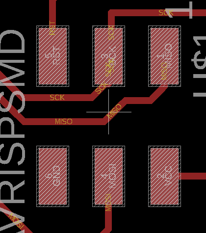
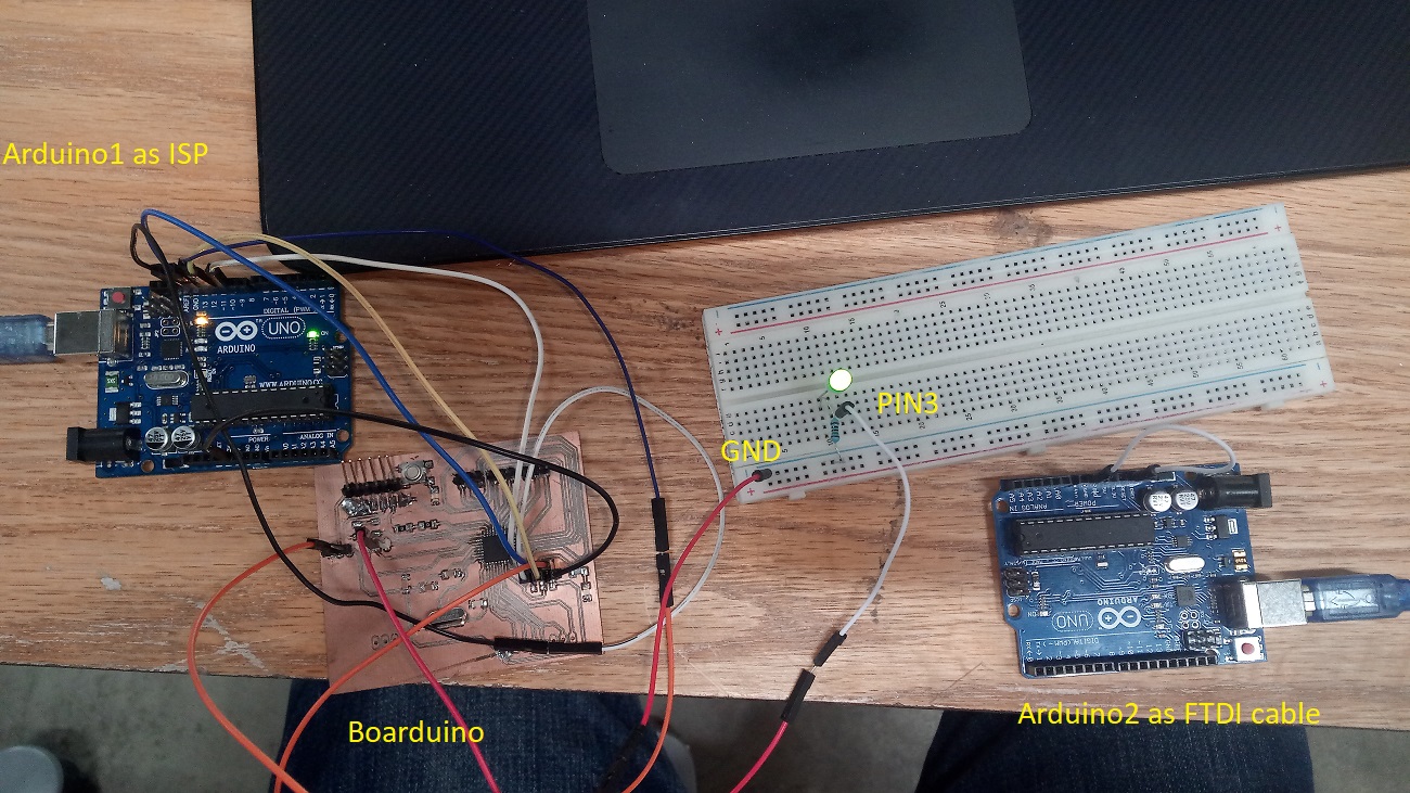
What Im going to do is just to make a serial communication between my board and the pc because I need to make a new board and fix the FTDI connection The first step is to connect the firs arduino as ISP with atmega boarduino to upload the code by the following connections:
SCLK: Serial Clock ------------------------> Arduino Pin 13
MISO: Master Input Slave Output ------> Arduino Pin 12
MOSI: Master Output Slave Input ------> Arduino Pin 11
RST: --------------------------------------------> Arduino Pin 10
VCC: Positive supply voltage -------------> Arduino VCC
GND: ---------------------------------------------> Arduino GND
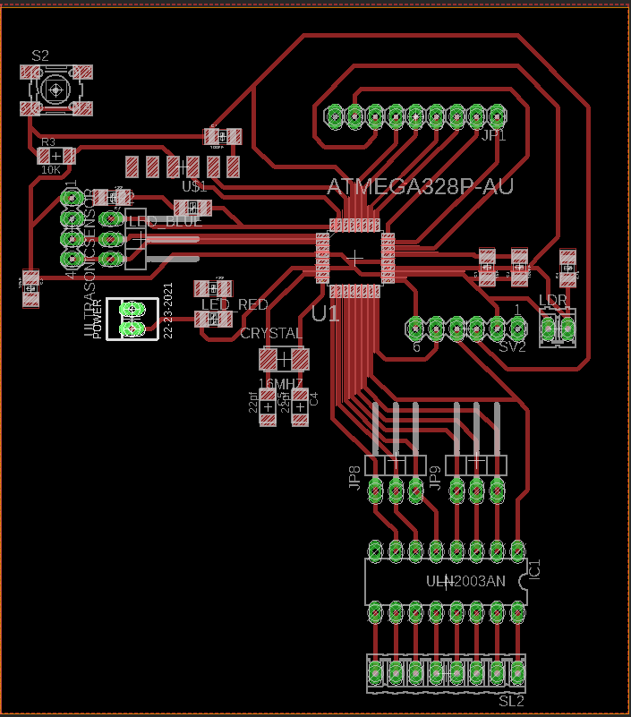
This is the board layout of my boarduino.
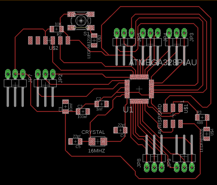
for more details about my boarduino you can see the output devices week decomentation
And this is the pin header
I have also breadboard with LED, and its connected with boarduino pin 3
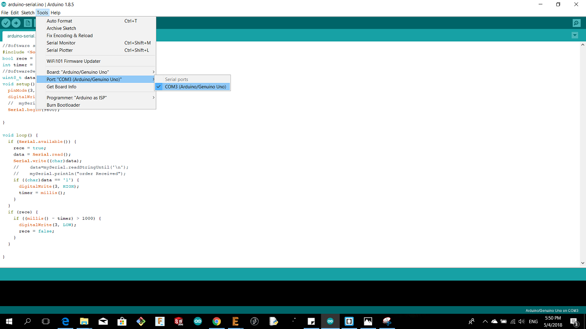
Now Im going to upload the code before that I checked the port COM as shown
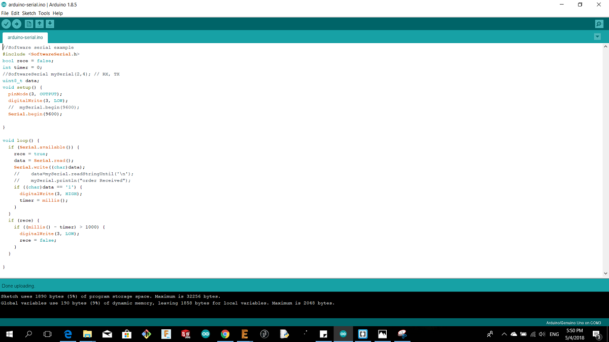
The upload using a programmer
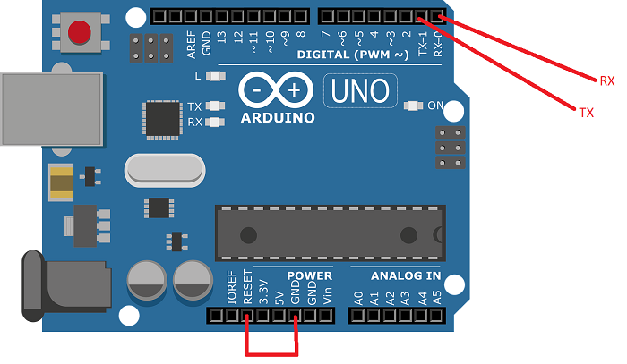
The second step after I uploaded the code I will connect the second Arduino as FTDI cable by the followin connictons :
Arduino TX------------->Atmega Boarduino TX
Arduino RX------------->Atmega Boarduino RX
Arduino RST------------->The same Arduino GND
After I connected the second Arduino with my pc I have to change the port for arduino 2 in order to open the serial monitor
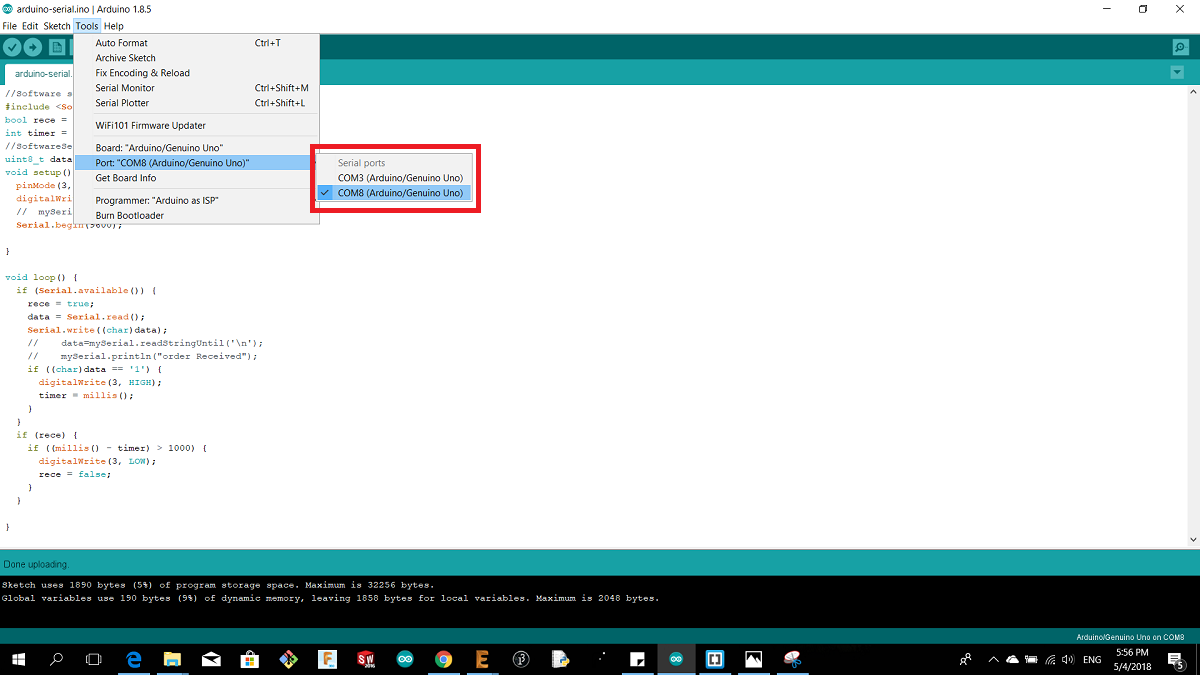
As shown I chose port 8 the I opened the serial monitor
PROOF
3.Serial Communication Between Two Boards
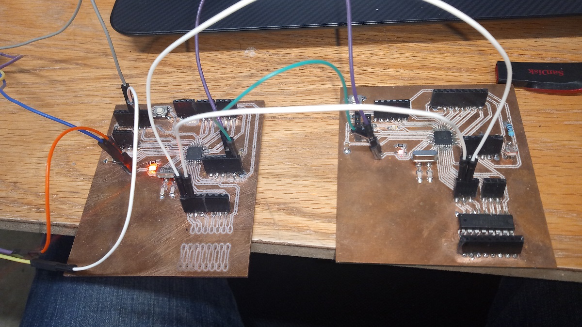
After I made a new boards and I fixed the problem by adding 100uf capacitor and 10k resistor in RST trace I connected two simmilar boards as shown
To communicate between my boards I want to use something called SoftwareSerial library, it allows serial communication on other digital pins, using software, so by using this library we can have two serials, one is hardware, and the second one is software.
This is the Arduino code that I used
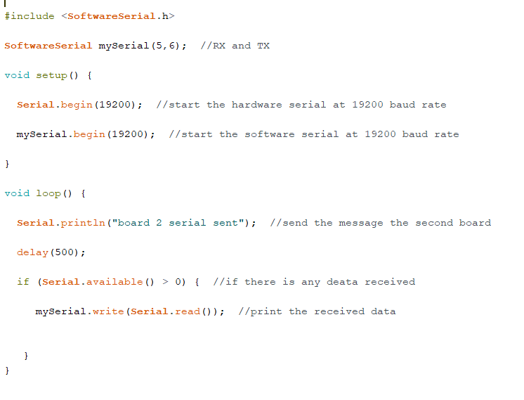
I have uploaded this code to the slave board and for the master board I just changed ("board 2 serial sent") to ("board 1 serial sent")
So I chose pin 5 and 6 to be the software serial so using the FTDI cable I connected it with the left board in the above picture and I connected the following
FTDI RX,RX with master board TX.RX
FTDI VCC and GND with the master VCC and GND
Master board software serial pins 5 RX and 6 TX with the slave board pin 6TX and 5 RX also the VCC and GND And here is the proov
4.Problems
When I connected my board via FTDI cable there was no serial comunication and I couldnt upload the code I thought the problem was just because I added a led and resistor to the rx and tx so I made another board and this is the schematics of it
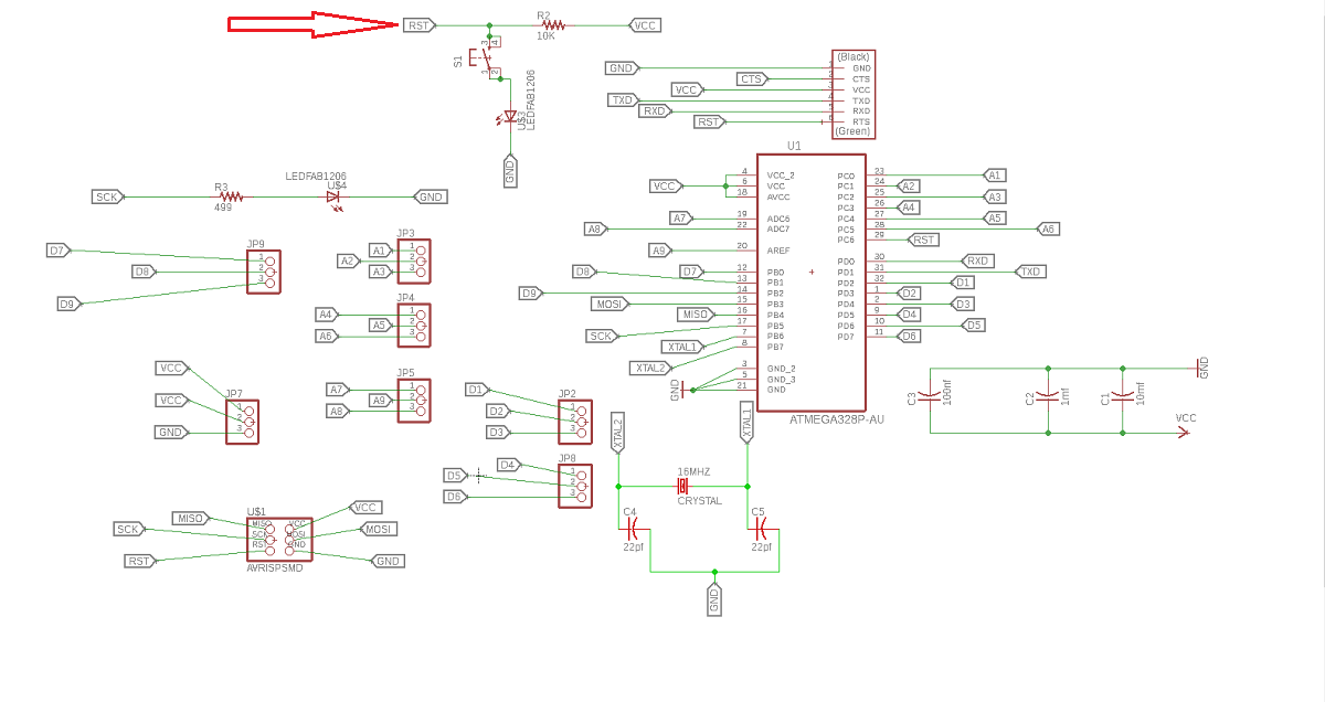
Unfortunately it did not work so I asked Daniel about it and he gave me the answer, for FTDI cable I should put 100nf and 10k resistor befor the RST pin in order to make it work so I did the same using autodesk Eagle and here is the designes

and here is the board after milling
Download WIFI Schematic and Board layout
Download the Code Of The Board and Pc communication
Download the Code Between The Two Boards
Download atmage328p Board schematic and Board layout