Week 7 | Electronics Design
Fab Academy 2018 | Archive
Designing ATtiny45
This week is of designing your own circuit board. In our lab all the components of ATtinty 45 were available so I decided to redesign the same. I made the design in Autodesk Eagle software. You can download the software from here
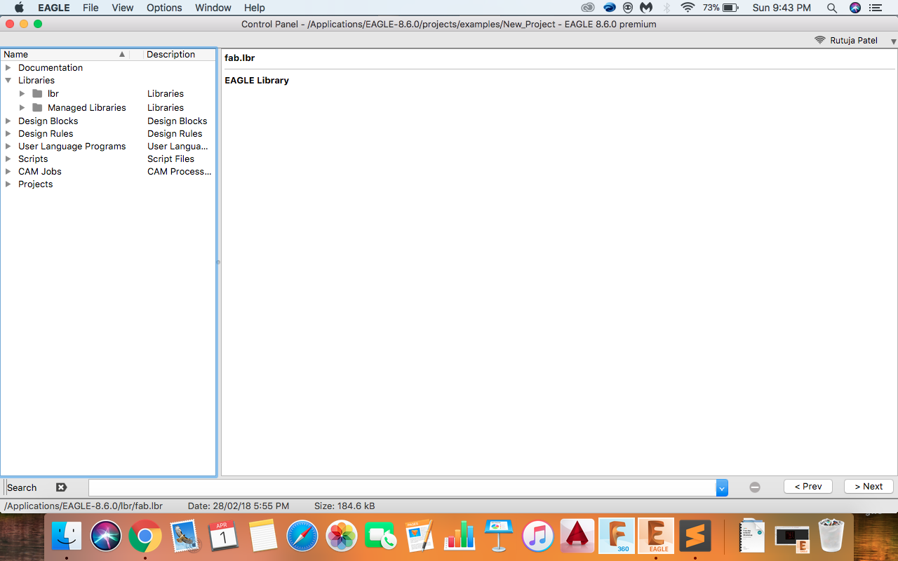
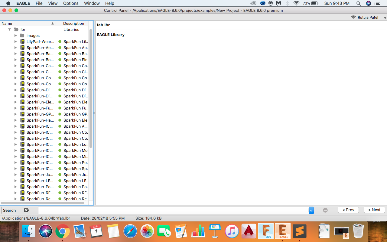
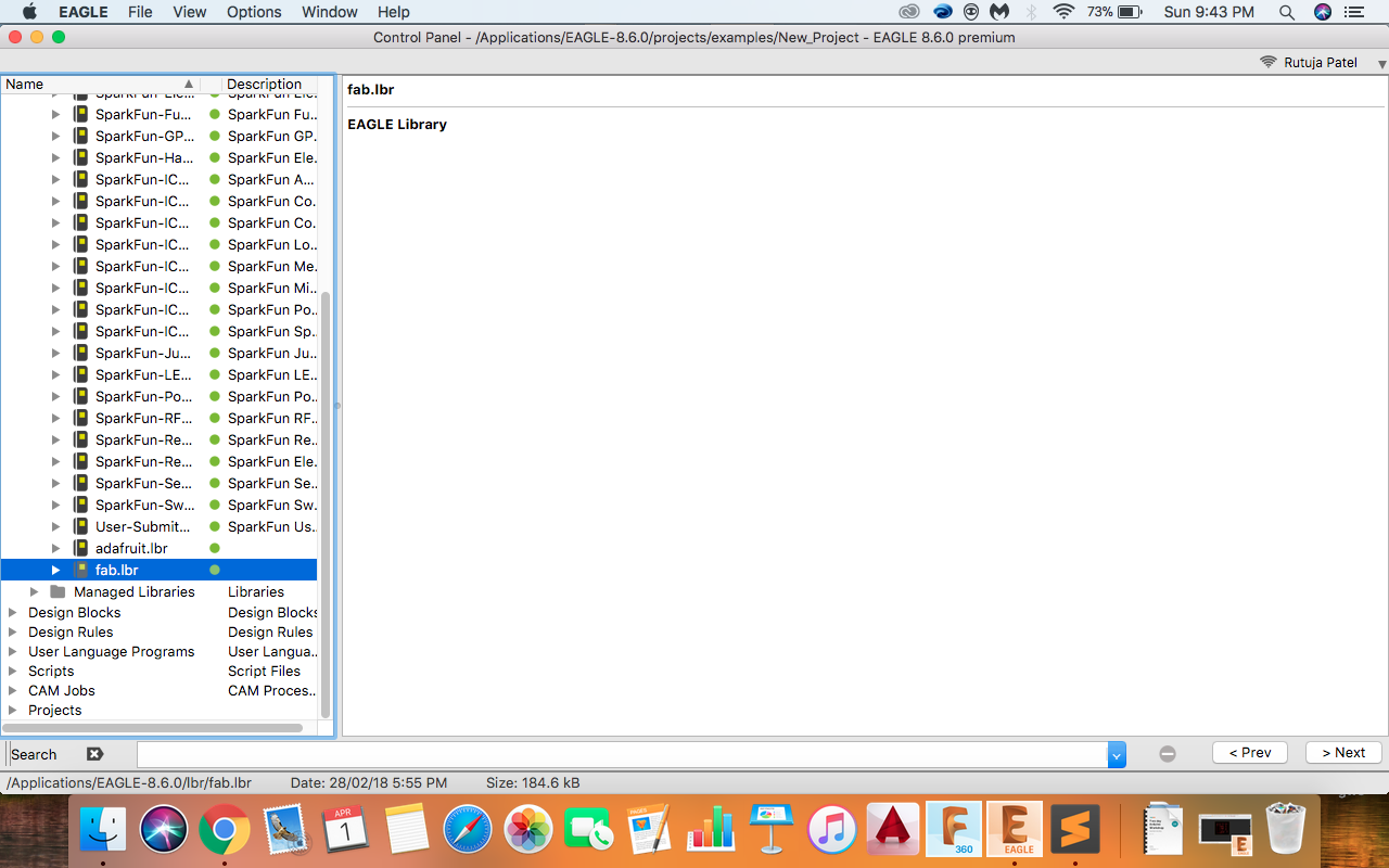
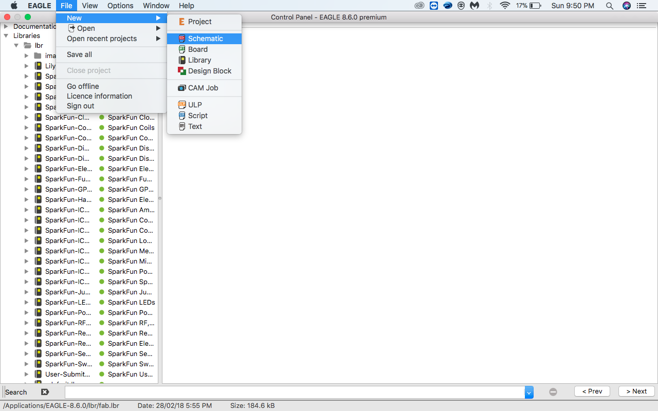
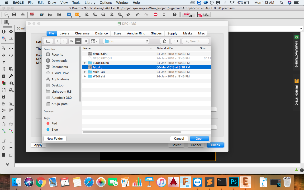
First step was to download fab.lbr and add it to Eagle Library. The process of openoing the library is shown below.
Steps :
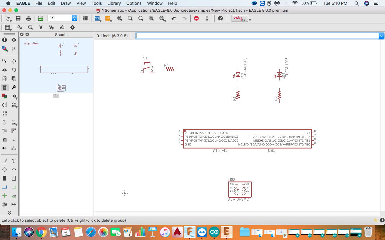
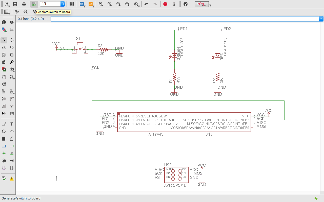
Next step is to make a schematic of the board we want to make. I decided to add two led's and one button and program it. I listed all the components that I will use so at the end I doon't get confused. Kishan Chavda who is an intern at our lab helped me to understand the eagle software and making schematic.
Components used:
- ATtiny45 IC
- AVRISP
- RED LED
- GREEN LED
- BUTTON
To open the schematic view rom Fille << New << Schematic. Now the schematic view opens and you can start making the schematic.
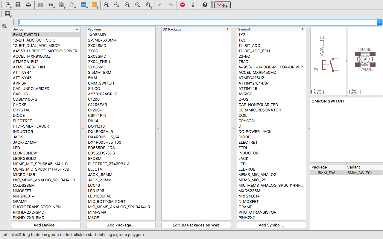
To add the components click the add icon in the schematic view and start adding the cmponents.
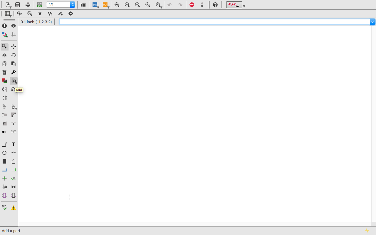
I took all the components from the fab library. It has almost all the components available.
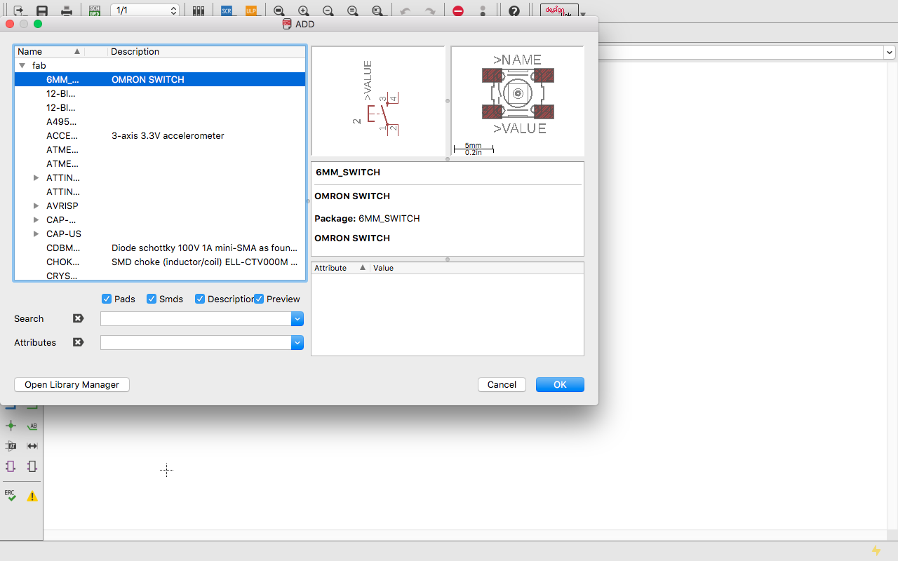
I found all the components and added it to the schematic.
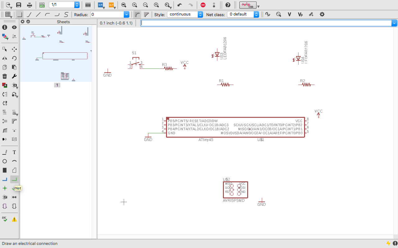
Now for connecting the components together we use "Net" icon from the control pannel. This command gives individual connections for each components.
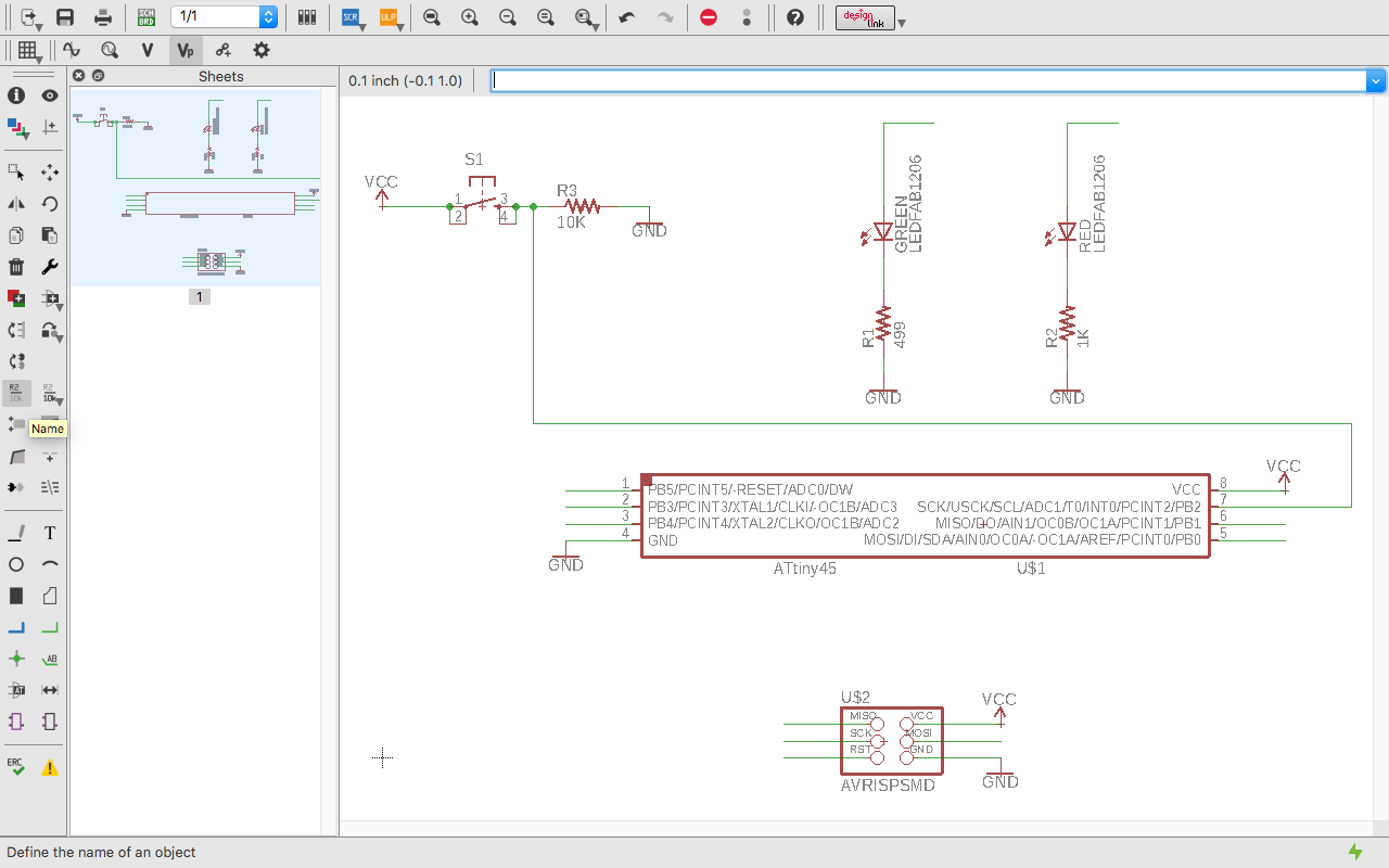
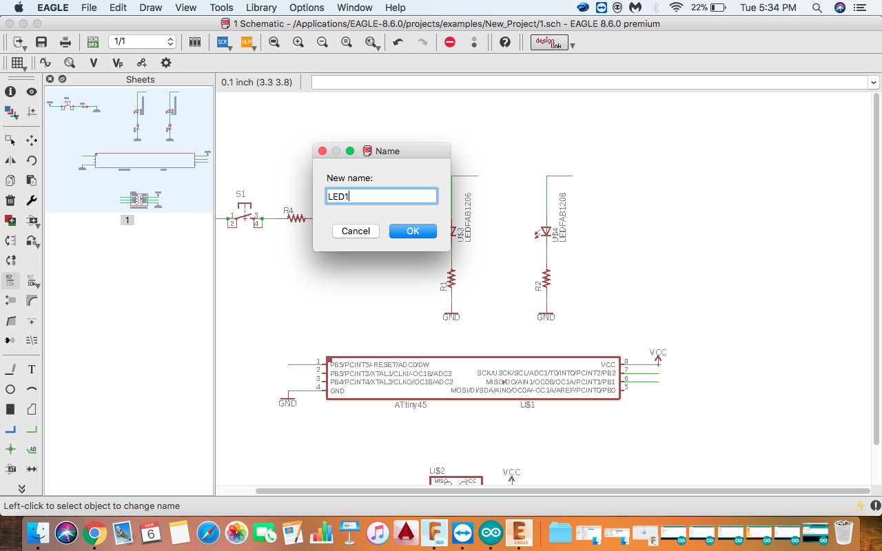
Use "Name" icon for naming the component. By naming the components, it becomes easy to differentiate the components and also easy to recognize the component easily.
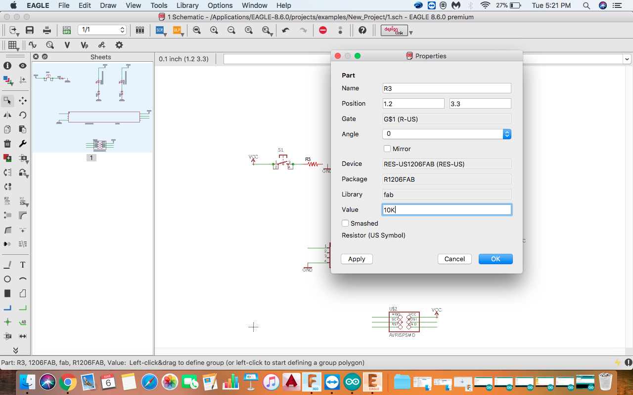
Giving value of the component. By giving the value, it is easy to diffierentiat the comonent and it becomes easy to recognise where the component is to be placed.
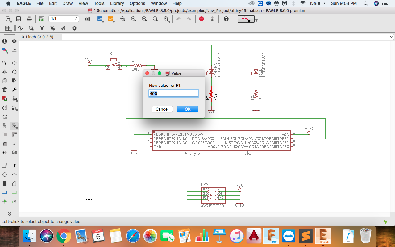
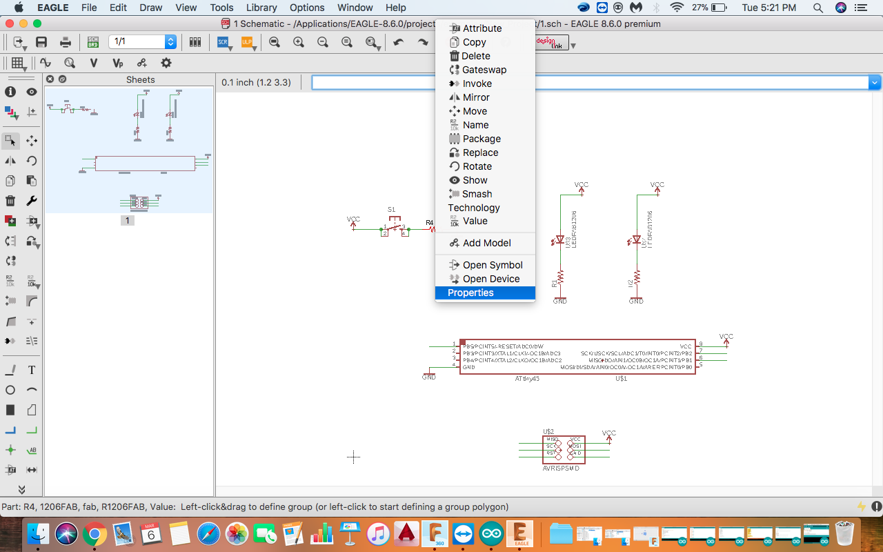
"Name" and "Value" of the component can also be changed by Right clicking on the component and changing the properties.
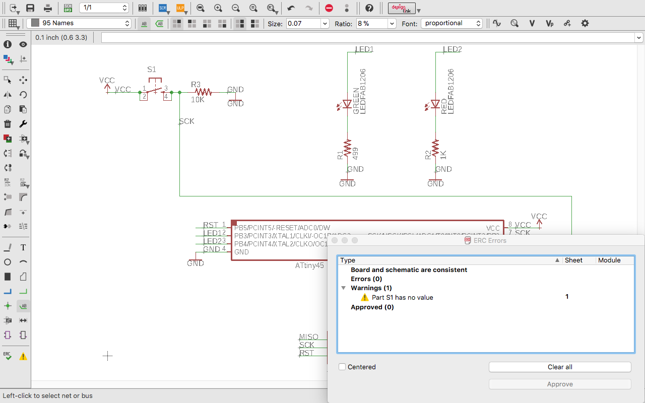
The "ERC" command shows the error in the Schematic. I got one 0 error nad 1 warning for not giving the value of switch. After correction there were no errors and no warning
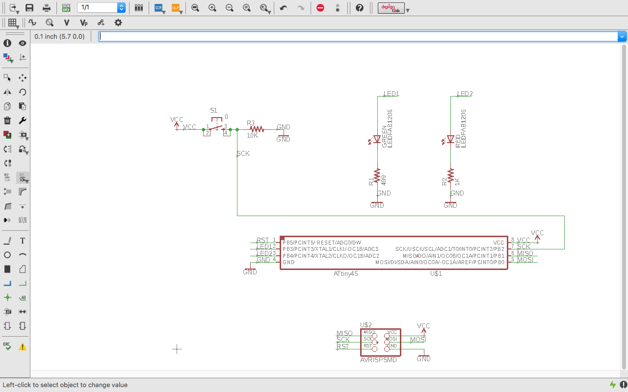
FINAL SCHEMATIC
After completing the schematic next step is to switch on the board view. From board view we can make export the image of the board we want to make and load it to the fabmodules.
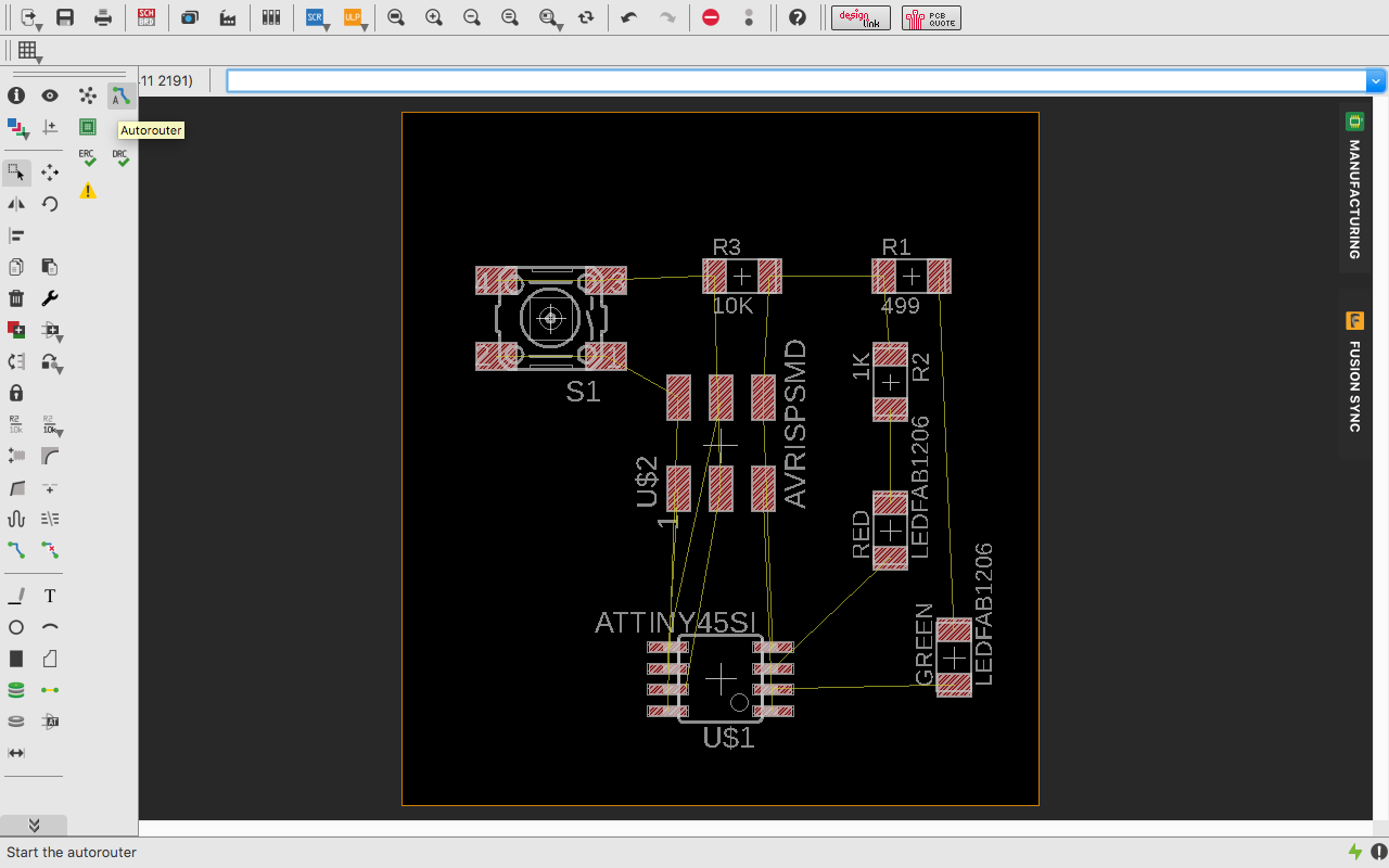
You can switch to board using the Switch to Board icon in the above pannel. In the board view you will have components unarranged and a big box becide it.
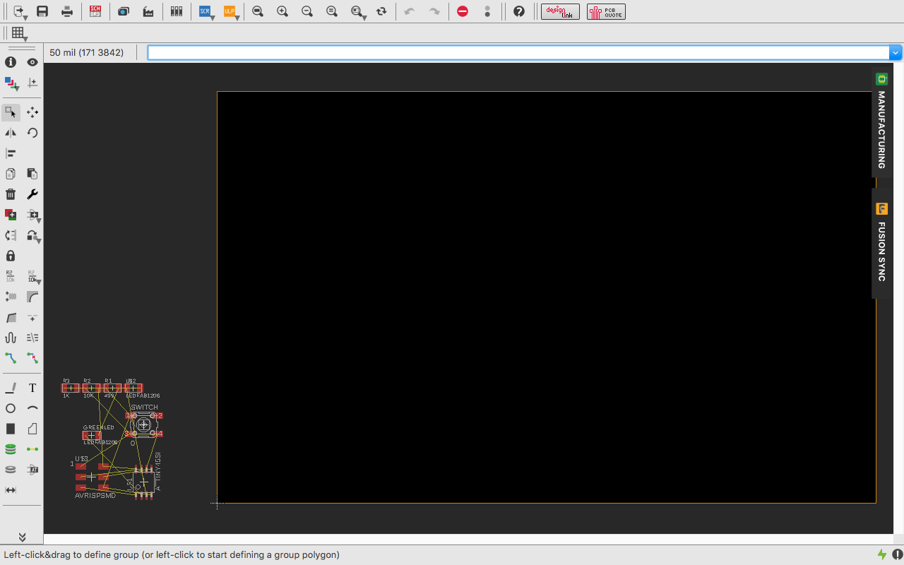
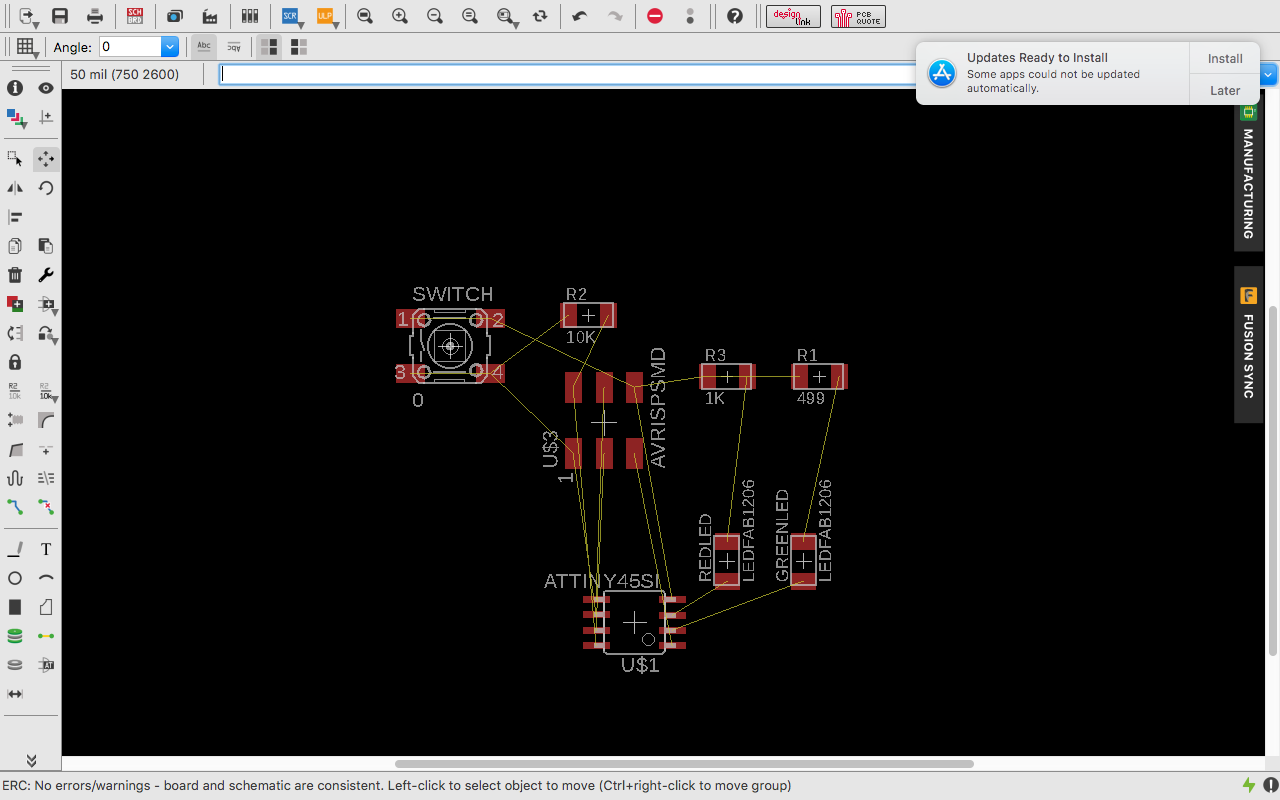
Drag all the components into the box and arrange them in a best possible way.
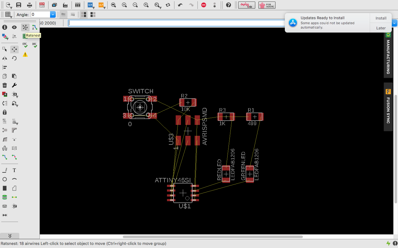
 For achieving the shortest connection path, there is a command Ratsnest in the left pannel. It makes all the airwire to connect to the shortest path.
I came to know about fab.dru from Arpi Maheshwari's website who was the last year fab graduate. The fab.dru has all the modella settings and rules. So I loaded it from DRC icon in the left pannel and loaded it.
I used Autorout command to make connection routs.
Steps :
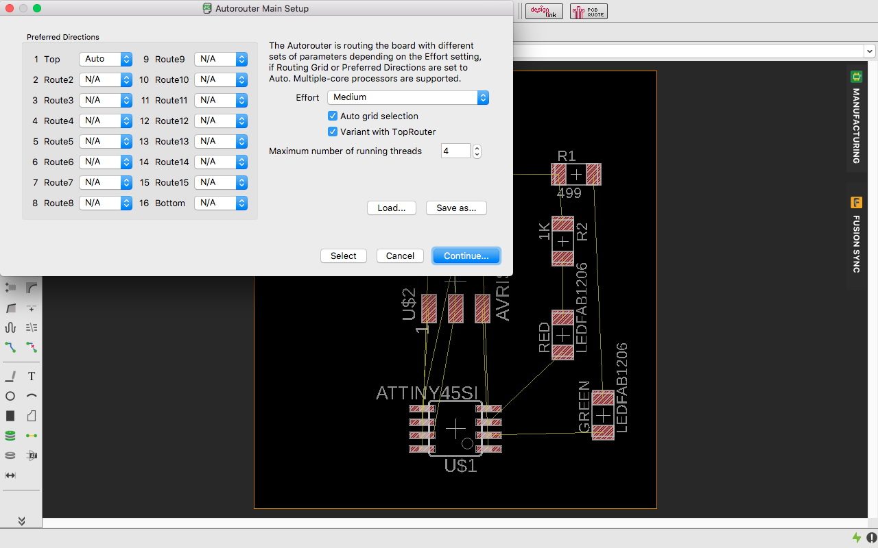
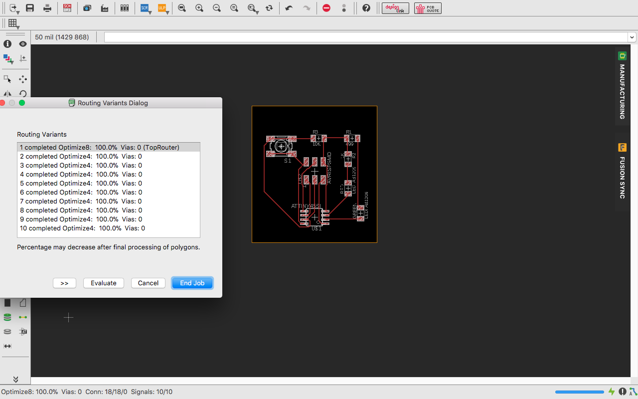
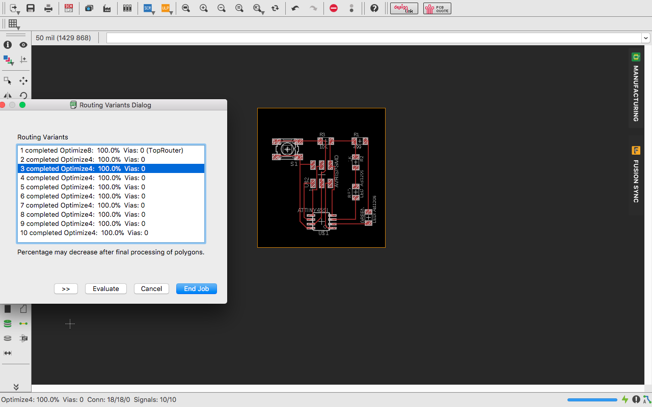
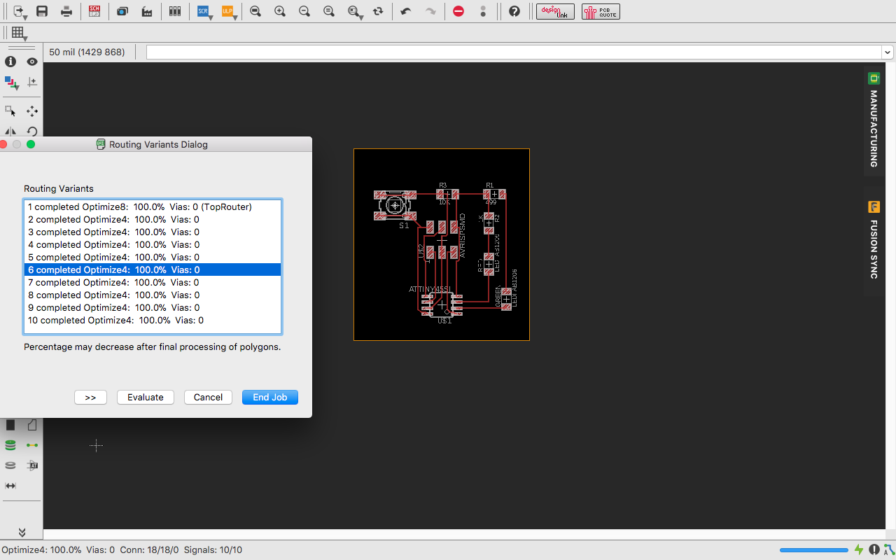
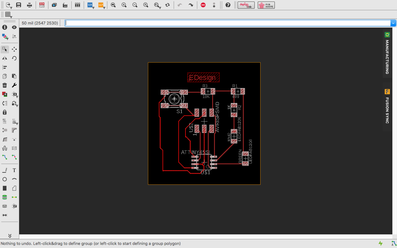
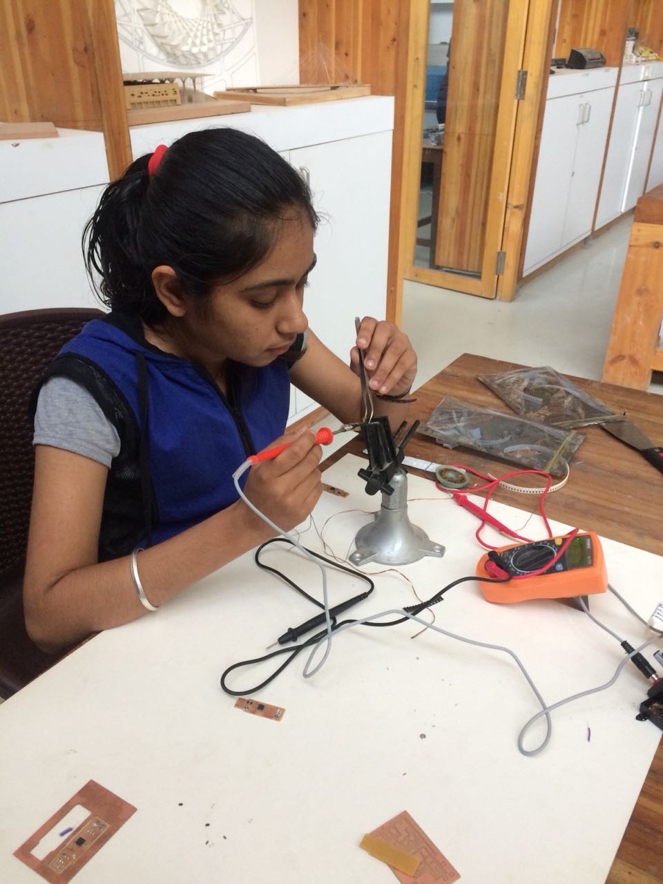
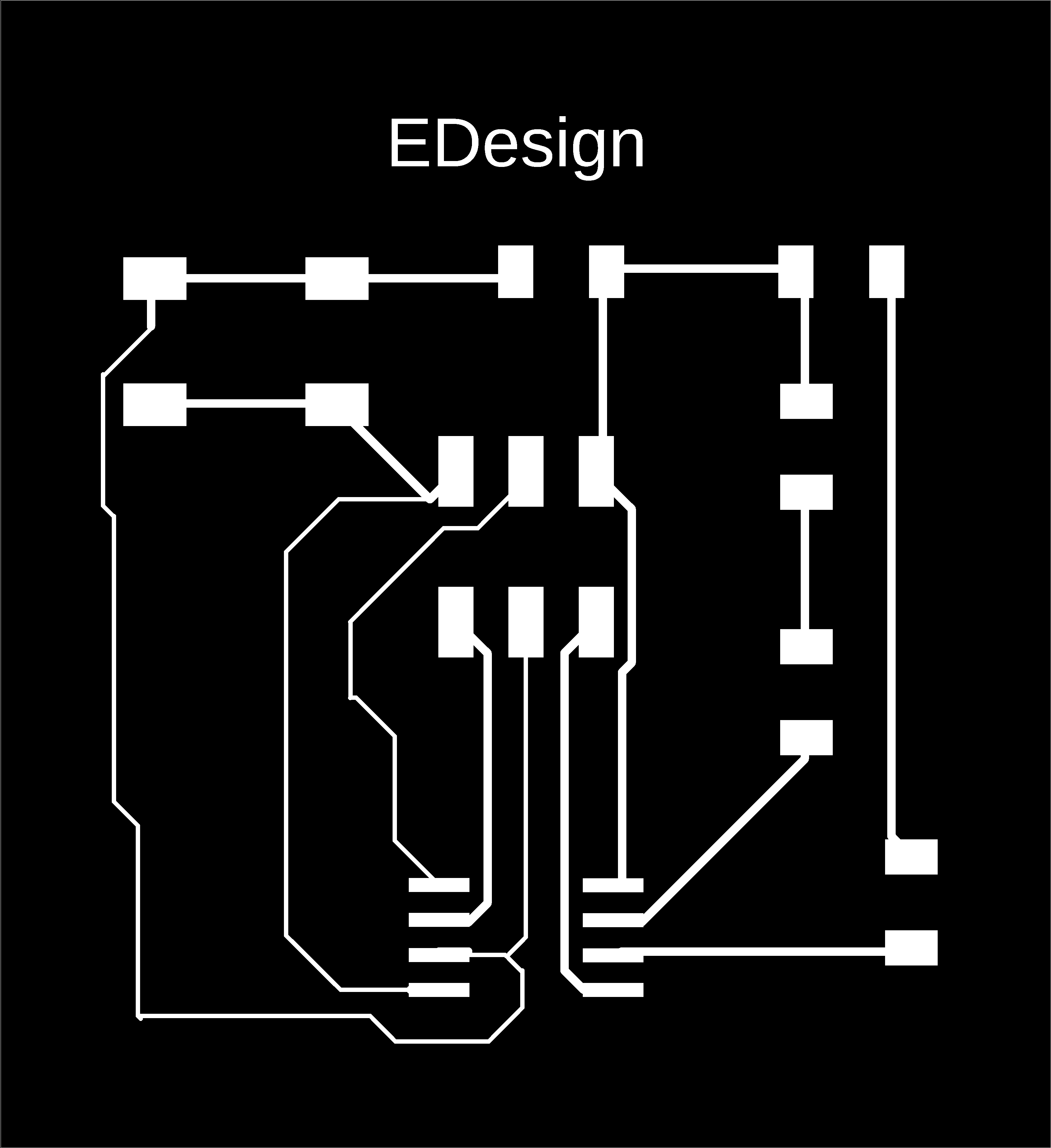
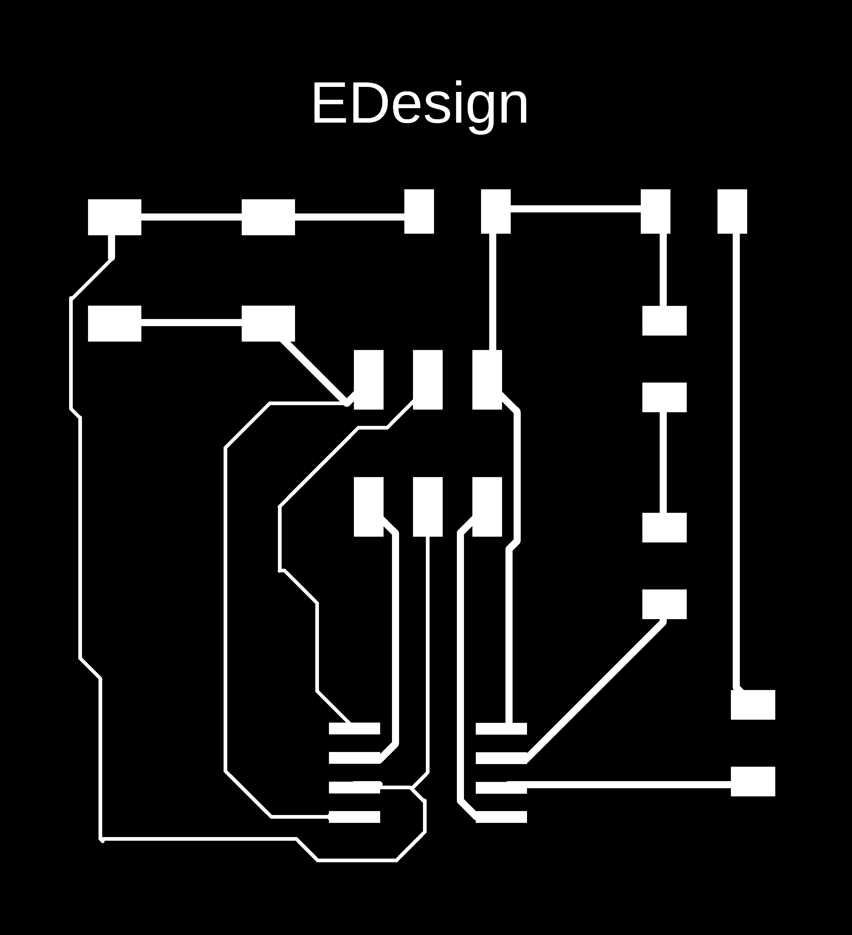
I choosed the design and modified it a bit because the traces were near to each other. When the traces are near to each other the either they will merge or there is a possibility that there is a chort circuit. My Final Board Design.
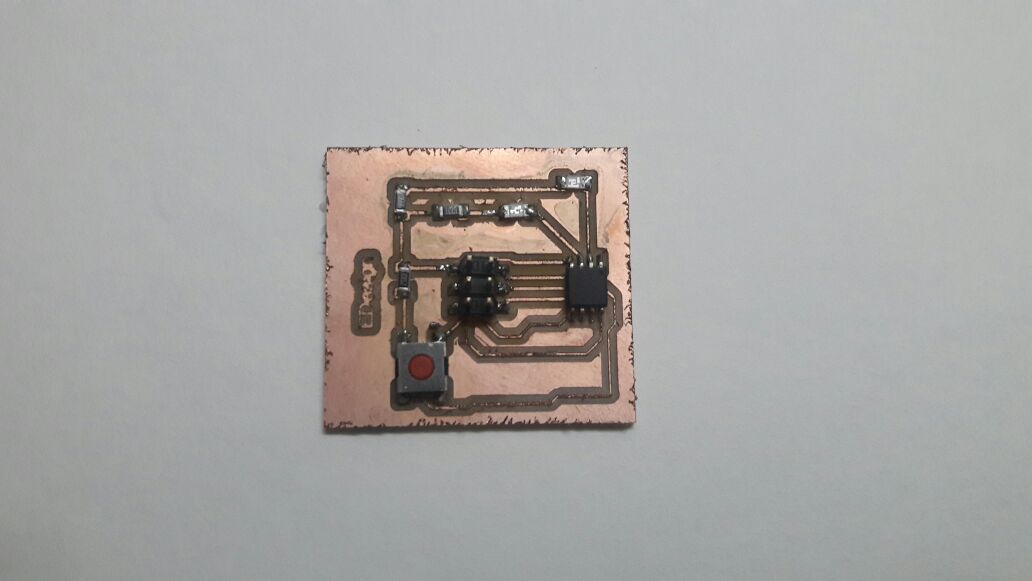
I milled the board in the new fab modules which got milled properly.
 You can check the group work from here.