

Week 7
Electronics Design
CHECKLIST
Shown your process using words/images/screenshots
Explained problems and how you fixed them, including how you worked with design rules for milling
Included original design files (Eagle, KiCad, Inkscape, .cad - whatever)
My contribution in group work is to understanding oscilloscope so we can take readings
Task to be done in this week
1 Understand electronics components function and read their data sheet
2 Learn circuit designing software and design your own circuit
3 Make circuit to glow led using button
Original files of this week
Electronics design
The important part of this week is to understand components used in circuit and understanding electronics circuit design as learning from this week will be carry forward to coming weeks so i decide to start this week by focusing more on electronics components and their use and design basic circuit to understand concept of circuit design
Important source for studying about electronics which i find relevant
Learning from this week
1 Use of component in circuit
2 Designing circuit on eagle
3 Testing circuit using arduino
About basic electronics components
here i am writing use of components in circuit which is very important for understaning and using them
1 resistors
we use resistors in circuit to regulate current ,ex if you have led and you connect it directely with 3v battery it blow out as 3v battery supply more current than which is required to glow led so you need to place resistor to regulate current in fabacadmy we are going to use 1206 size smd resistor , rule for finding resistace is V=Ir
2 capcitors
we use capacitor as filter for blocking dc signal in circuit ,micro farade range capacitor are generally used in this application , they are also use for storing charge as much easier to charge and discharge large size capacitor are used for this
3 button
button are components which are use for circuit break in four pin button one side pin are connected and other two pin are also conneted
4 resonator
Resonators are used to either generate waves of specific frequencies or to select specific frequencies from a signal
this are connected to clock pin in circuit as they are crystal used when we need to communicate with other device
5 inductor
it stores electrical energy in a magnetic field it is use for signal filtering
in congriguration 1 the inductor blocks AC current, while allowing DC current
In configuration 2 , the inductor decouples DC current, while allowing AC current to pass
6 DIODE
it conduct current one side and restrict opposite flow of current so prevent current flow in wrong direction
A voltage regulator circuit can be designed using a zener diode to maintain a constant DC output voltage across the load in spite of variations in the input voltage or changes in the load current.
7 TRANSISTOR
A transistor is a semiconductor device used to amplify or switch electronic signals and electrical power
how to connect them in circuit
To connect the transistor as a switch in a circuit, we connect the output of the device that will switch on the transistor to the base of the transistor. The emitter will connect to ground of the circuit. And the collector will connect to the load that the transistor will turn on and the supply voltage of the circuit
8 micro controller
this are brain of your circuit it contains one or more CPUs (processor cores) along with memory and programmable input/output peripherals) when you want to built your circuit by using any logic of controlling you may use micro-controller
ex atmega 44, atmega 45 , atmega 328
atmega 328 have more input output pins than 44 which have more than 45 for getting more details of this components you have to refer there data sheet
9 circuit design
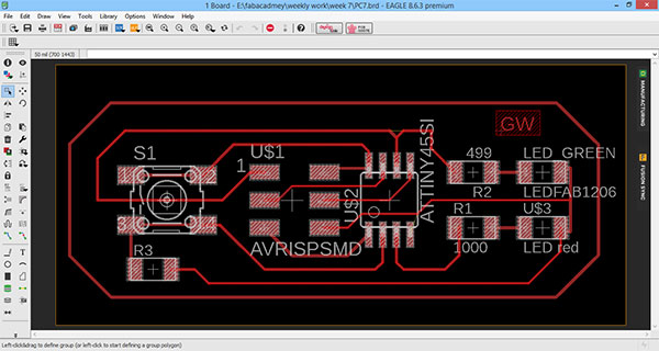
the term "circuit design" often refers to the step of designing the schematics of the integrated circuit , for starting with circuit design here our ilocal nstructor asked me to first use attiny 45 to design simple circuit than to design hello echo board
Steps to be followed for circuit designing
1 write problem statement / act to be performed (What the board will do)
here we are taking application of glowing different led with same button as when we press button once one colour red led will glow and on pressing second time green led will glow
2 Identify the components required in the board
for this i need
1 smd red led
2 smd green led
3 resistor for red led
4 resistor for green led
5 button
6 avr isp 6 pin header
7 atmega 45 micro-controller
About eagle
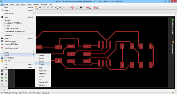
EAGLE is a scriptable electronic design automation application with schematic capture, printed circuit board layout, auto-router and computer-aided manufacturing features you can download this software from here
this is easy to use i followed tutorial of Jeremy Blum for a very hands on experience with Eagle through a video series of 3 videos.i watched first two video as in he is making schematic for two layer pcb but you may learn basic steps for this from it
to start with making circuit
Getting start with eagle
Step 1 Making new project to draw schematic
this is start screen of eagle

here you will get option to start new project and assign a name to your projects
project->examples->new projects
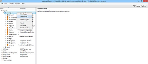
here click on your project to select new schematic

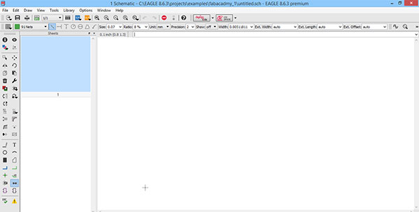
Step 2 - Add library and import component
Here on this page you can draw the schematic i.e connection diagram of what to connect
now download the fab library and other library also as this library have components
footprint which we will use in making circuit
i get this library from gautam's page of fabacadmy 2017 student
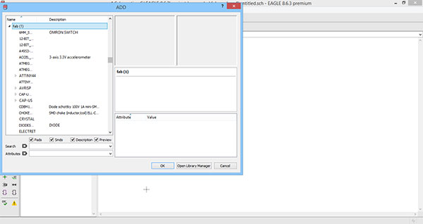
Import component first from fab library if not available than import from other library but in this you have to check its footprint from its data-sheet

This is AT tiny 45 IC which i use in my board

3 Draw circuit sketch and make schematic
As per the sketch i import all component from library , for linking component you can use net tool or link by giving same name to stretch net on both component as shown in next step
Here i assign MISO name to first pin by double clicking stretch net of MISO pin
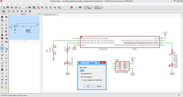
Now at pin 6 of MISO assign name as MISO on its stretch net

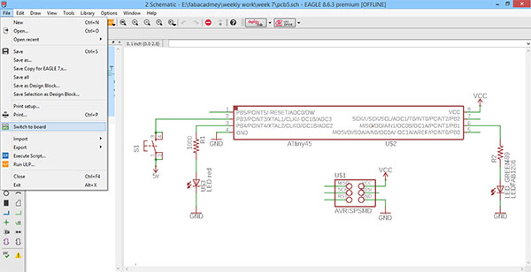
Step 4 Make board which is design layout which you are going to trace
Once all connection are done now go to file menu and select switch to board for getting pcb connections layout
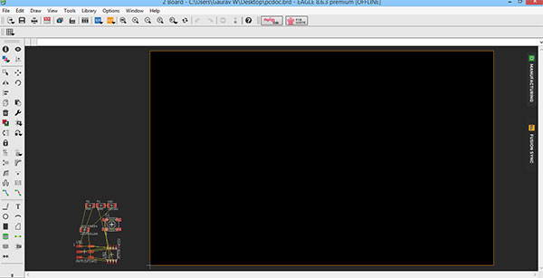
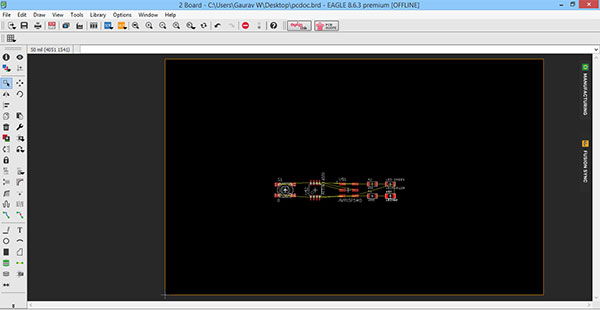
Drag all this component into board by simply click and drag
Arrange the component such that minimum airlines (yellow lines) cross each other and as per design which you want to give to your circuit
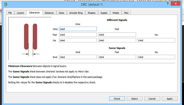
Now click on DRC ( Desgn rule check) here you can specify clearance between your component

here i have specified 14 mil which is 0.355 mm for clearance
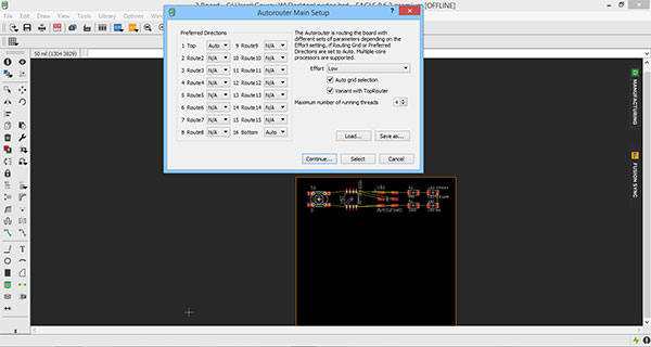
Step 5 Auto route your board which will give you trace path of your schematic
now go to tool and select auto-routing
this will convert all airlines into net lines which will be on your final board and also make optimized track
here after auto routing i find error in my board that ground of At Tiny and isp are not connected indicated by blue line and green dot between them you can also click on erc in tool to see this error

Step 6 Go back to airline view and rearrange component and again do auto routing till all erc error not removed
In this circuit you can find no two lines are intersecting and have sufficient spacing

Mistake i did in writing signature on board
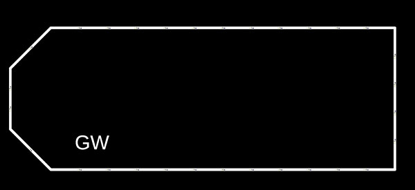
Now we draw the outer lines of circuit for cutting lines and use text tool if you want to write your signature write in same layer here
i draw this on another layer which is cutting layer by selecting from top but this is wrong as this name is cut out

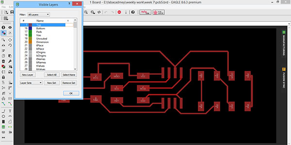
Now Go into all layers view to see different layer
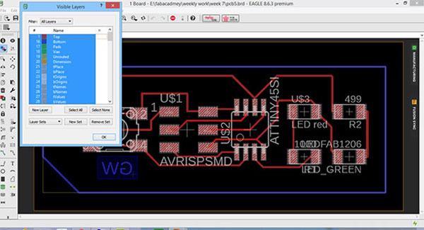
Now select the top layer only to get trace
Select bottom layer to select outer boundary as here i have draw boundary on bottom layer you can select any layer for this
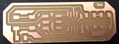
This is trace for milling
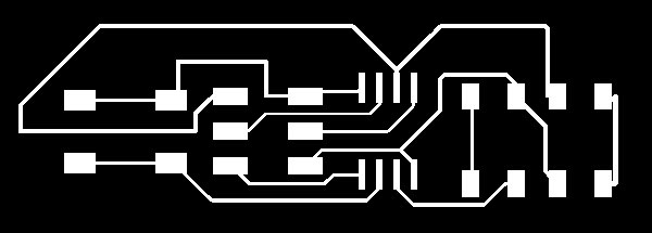
Follow similar steps above to get cutting schematic
This is the final pcb which i get and i solder component over it ,
mistakes i did in this are
i put my signature in cutting layer so its cut out completely also found my button is not working later i found the reason for this is that i have not attach resistance with button connecting to ground so i add a resistance and also changed the position of led
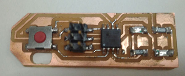
All the connection in this circuit are ok so i solder this to check it functionality
Redesigning the circuit
Redesigned circuit ,this is the final circuit which works with switch ,in final circuit i also changed position of led
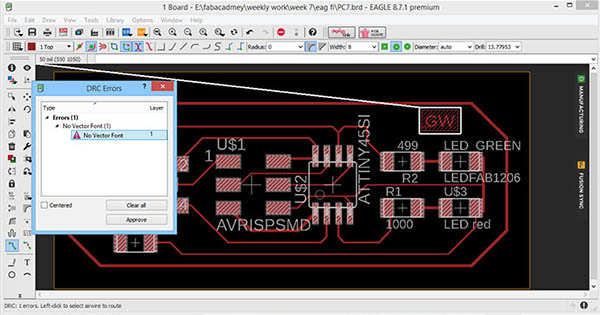
Drc Check
DRC check means design rule check for final circuit must check drc for which go 9o to tools and click on drc
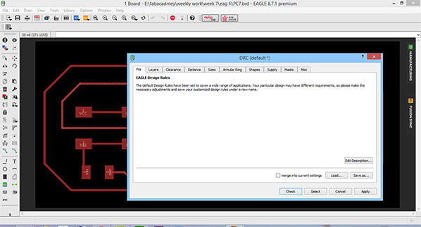
click on load and insert the default drc check file i.e i download this from link fab drc check

it ios showing only one error which is no vector found for text which we can ignore too proceed as there is no error in our board considering to milling
Milling Board
In week 5 i mill board using offline version of fabmodule so here i am milling my board using online version of fabmodules and all the steps regarding the setting tool and board will be same which i followed in week 5
Go to milling page for steps i fellowed in milling
this contain steps of setting milling board using online version of fabmodule
Adding component over circuit
The steps i followed for soldering this board is same what i did in week 5 so refer week 5 for more details of soldering board

This is the final pcb which i get after adding component


Another view of above pcb
Component Required
Programming board using Arduino
here i am programming using arduino and i also programed the same board using fabisp in week 9
this is start window of arduino

for making arduino as programer we need to first select board as arduino genuino uno

now go to file -> example->Arduino ISP ->Arduino ISP

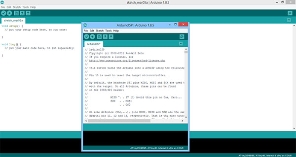
Run the command in this window ,thiis will make your arduino as programmer for this click on -> on top
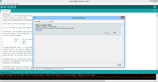
now go to preferences in file menu as we need to download At-tiny library


here is a link( get link) which you need to paste there and click ok
Select board in tools -->board manager

in board manager search AT tiny 45

install the board library from here
now go to tools and set
processor as AT tiny 45,
clock 8MHZ,
port COM5 (arduino genuino uno )

select programmer as arduino as ISP
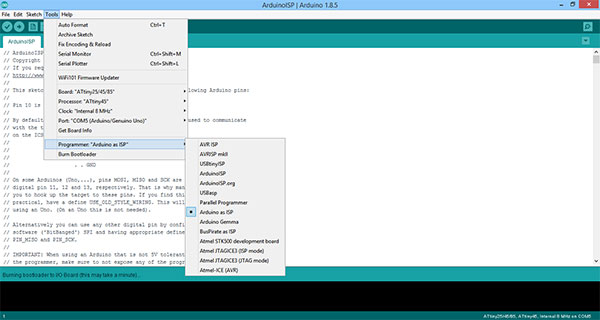
now go to tools and board arduino guneino uno >AT tiny 45

now go to tools and burn bootloader

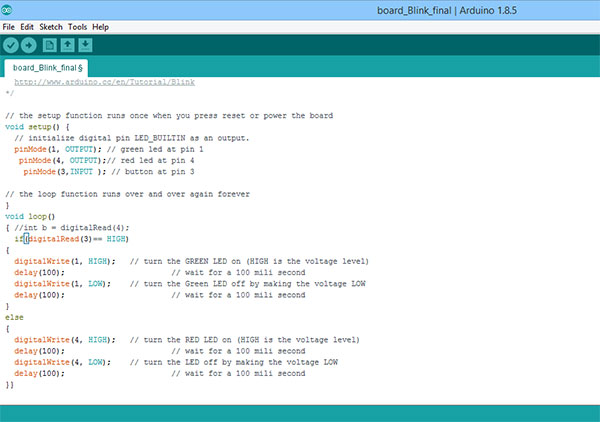
now attach the board to arduino board and go to blink example code and modified that

this is working video
i also programmed the same board using fabisp in week 9 for which you may refer my week 9 assignment
Conclusion
The task of this week is to design electronics board using eagle software which is done successfully and i also tested the board and programed ,

This work by Gaurav wadhwa is licensed under a Creative Commons Attribution-NonCommercial 4.0 International License.