Electronics Design
![]()
Introduction
This week is all about electronics designs, that means getting to know the whole process from designing a schematic and a board, milling the PCB, soldering and programming. I have no previous experience with soldering (except for helping my dad do the soldering when I was around 10 years old). That is why, this was a really long week for me and it seems like I did mistakes everywhere I could. What is more, we did group assignment this week is to try out the test equipment in our lab.
Schematic and Board Design
So, the first step is to Design schematic and board files in EAGLE. Here is a tutorial, which I used for working on this phase. For this week we had to prepare a Hello World Chematic and, additionally, we were asked to add at least one button and one LED (including a current-limiting resistor) into our board design.

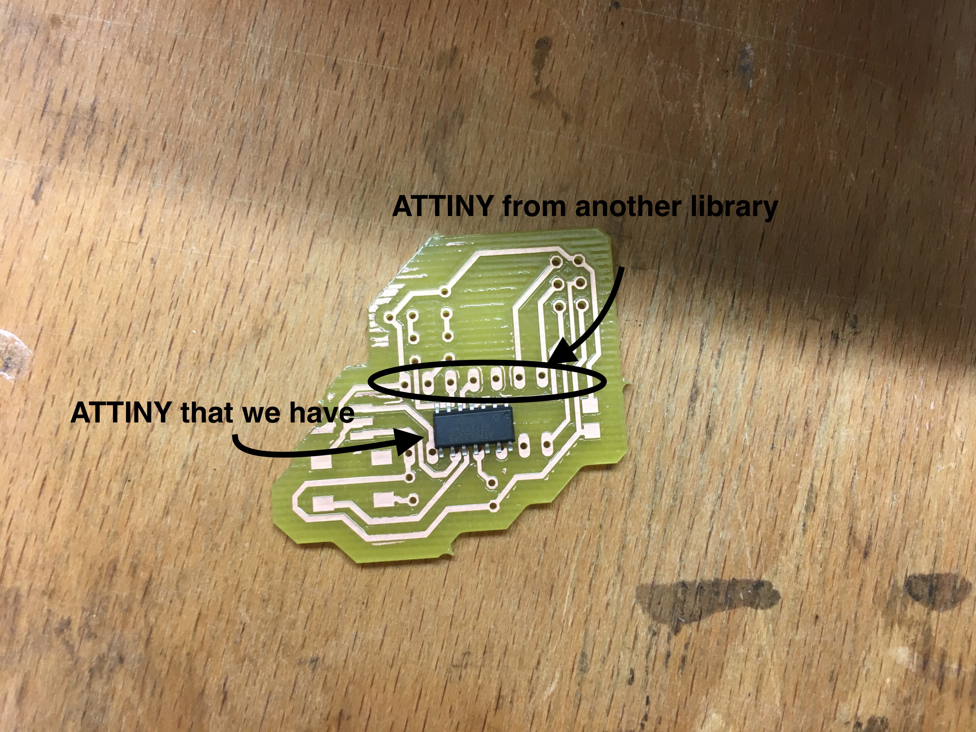
The most challenging part during the design was finding the correct digital components that represent the desired components on the real world. As I told already, I did a lot of mistakes. I choose a wrong ATTINY, so that after milling I got this:
Step-by-step design of schematic:
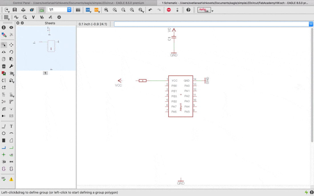
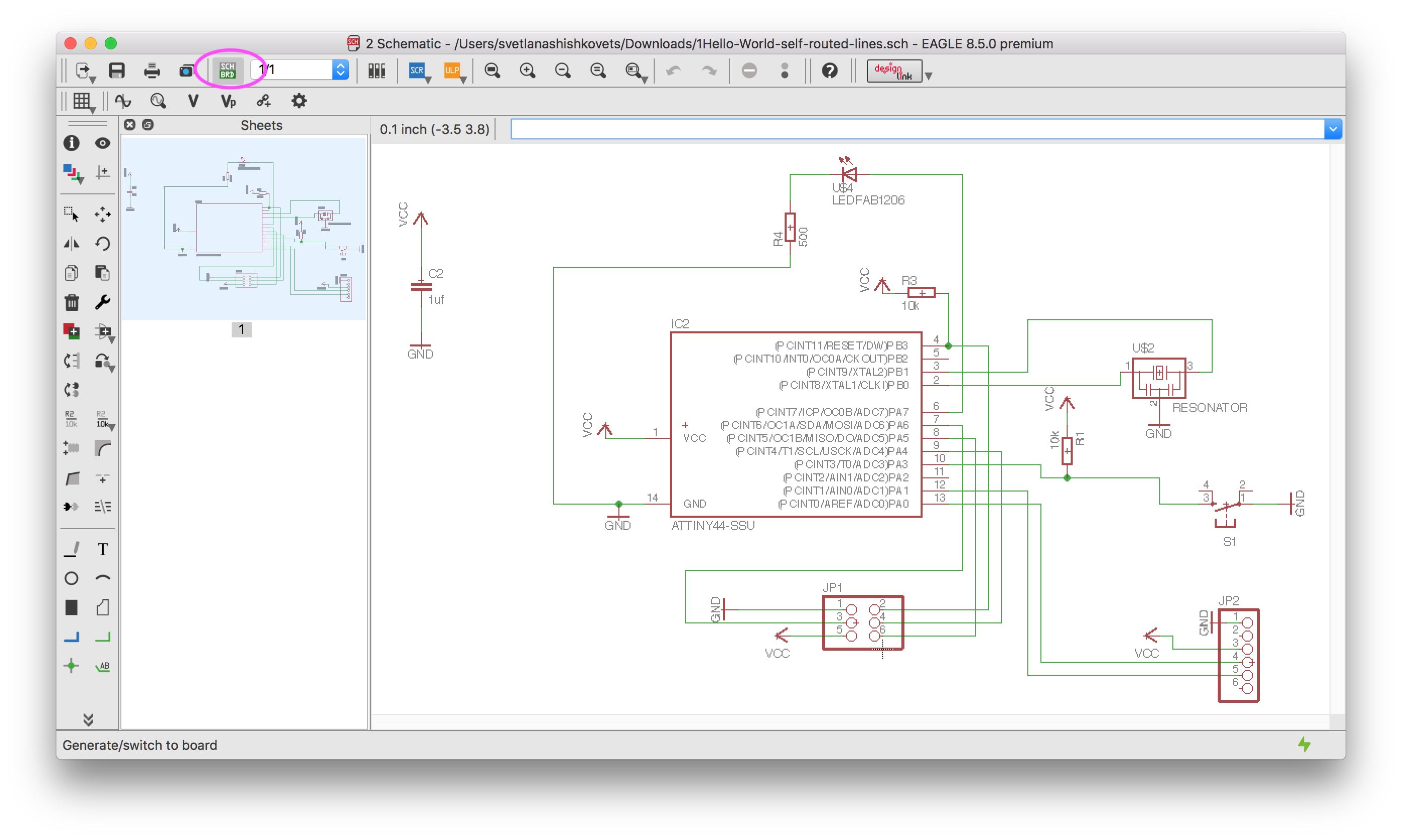
But then, after changing to a proper ITTINY, my schematic looks like this:
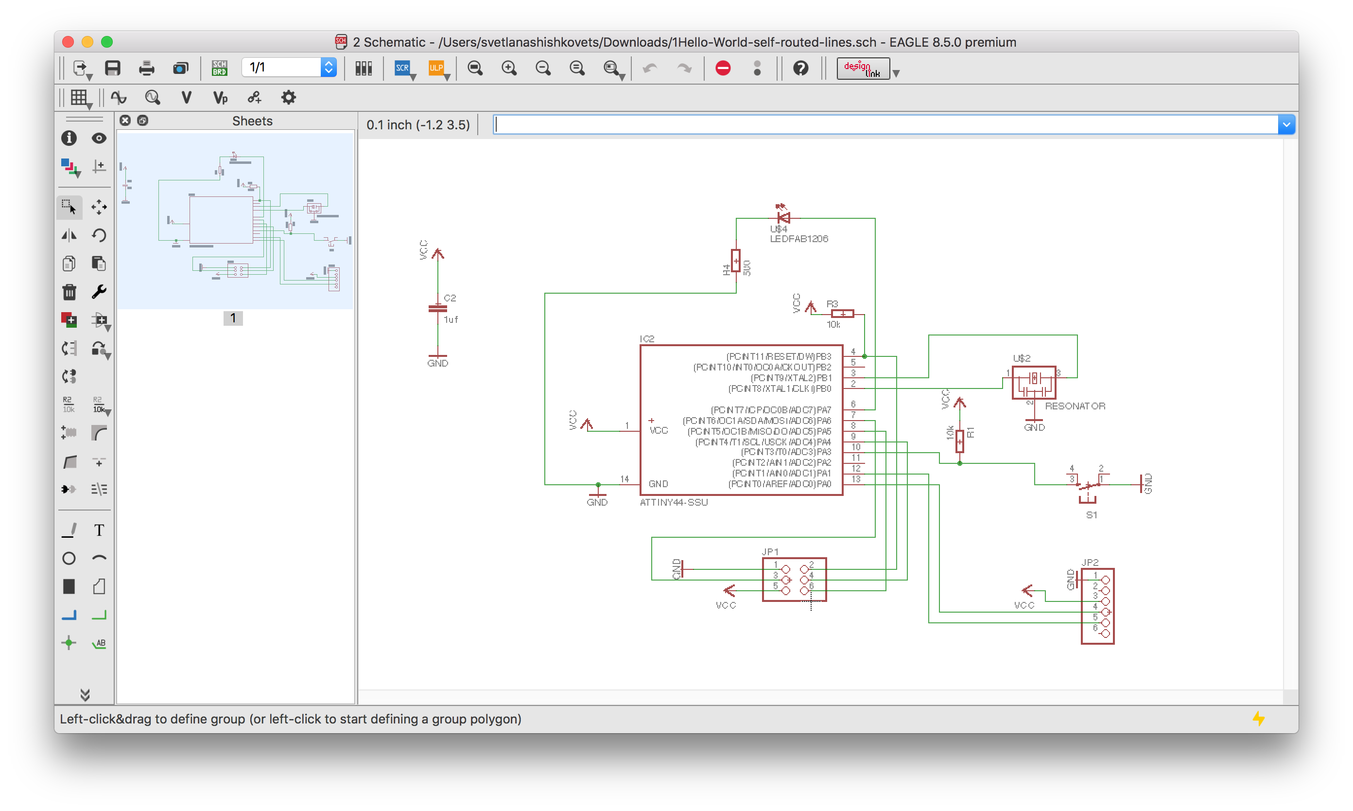
Next step is to do a board from schematic.

Next step is to move all details of board, so that crossing of yellow lines was minimum.

Eagle provides an autoroute option. But it is not always ideal, so here I got some "Bottom" connections. That is why I did it manually. What is more, I wanted the routes to have a bigger width than with the autoroute tool(16 instead of 8). Anyway, sometimes autoroute gives really good solutions.

At the end I wanted to make as less lines inside ATTINY, as possible. So, this is my final board:

All the schematic and board files can be found at the very end of this documentation.
ERC and DRC check
One more nice feature of the eagle is electronic rule checker(ERC) and design rule checker(DRC). ERC basically checks for k for the following issues:
- Are all of your nets properly connected and labeled on your schematic?
- Do you have any conflicting outputs/inputs on your schematic?
- Are there any open or overlapping pins and ports on your schematic?

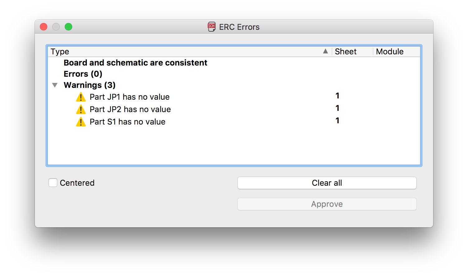
The command DRC checks a board against the current set of Design Rules.
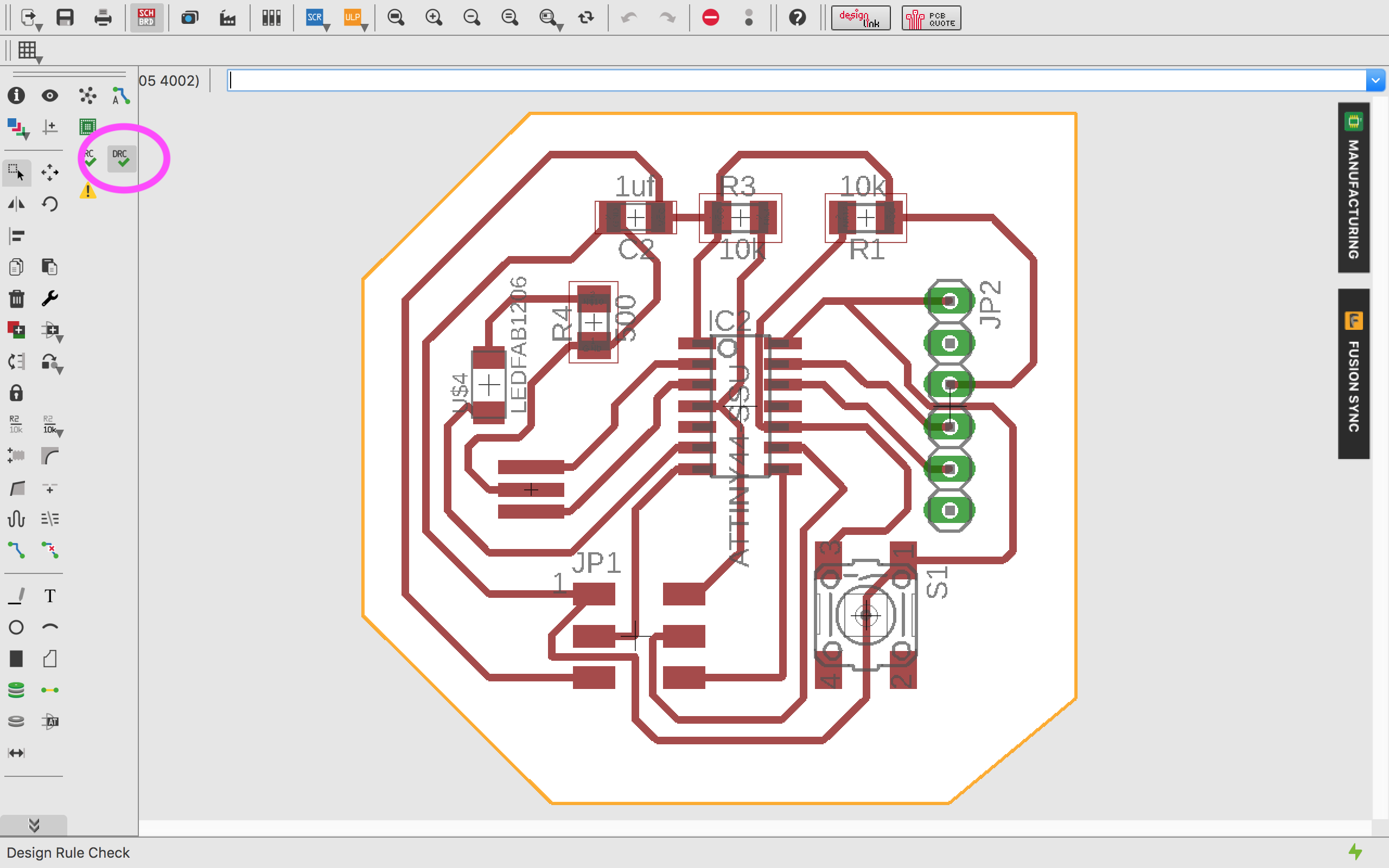


As you can see above, I had no design problems and just a small warning about the values of components, which is not important. So, I am ready for the next step.
Cam Processor
Quick instruction and files(.CAM and .drl), that would be needed during this phase could be found here. The instruction how to make a Cam Processor and how to use the CircuitCAM Software it is basically the same as in Electronics Production assignment .
Board Master Software & Milling
Our Fab Lab has a LPFK milling machine. With the software "boardmaster" you can control the milling machine.
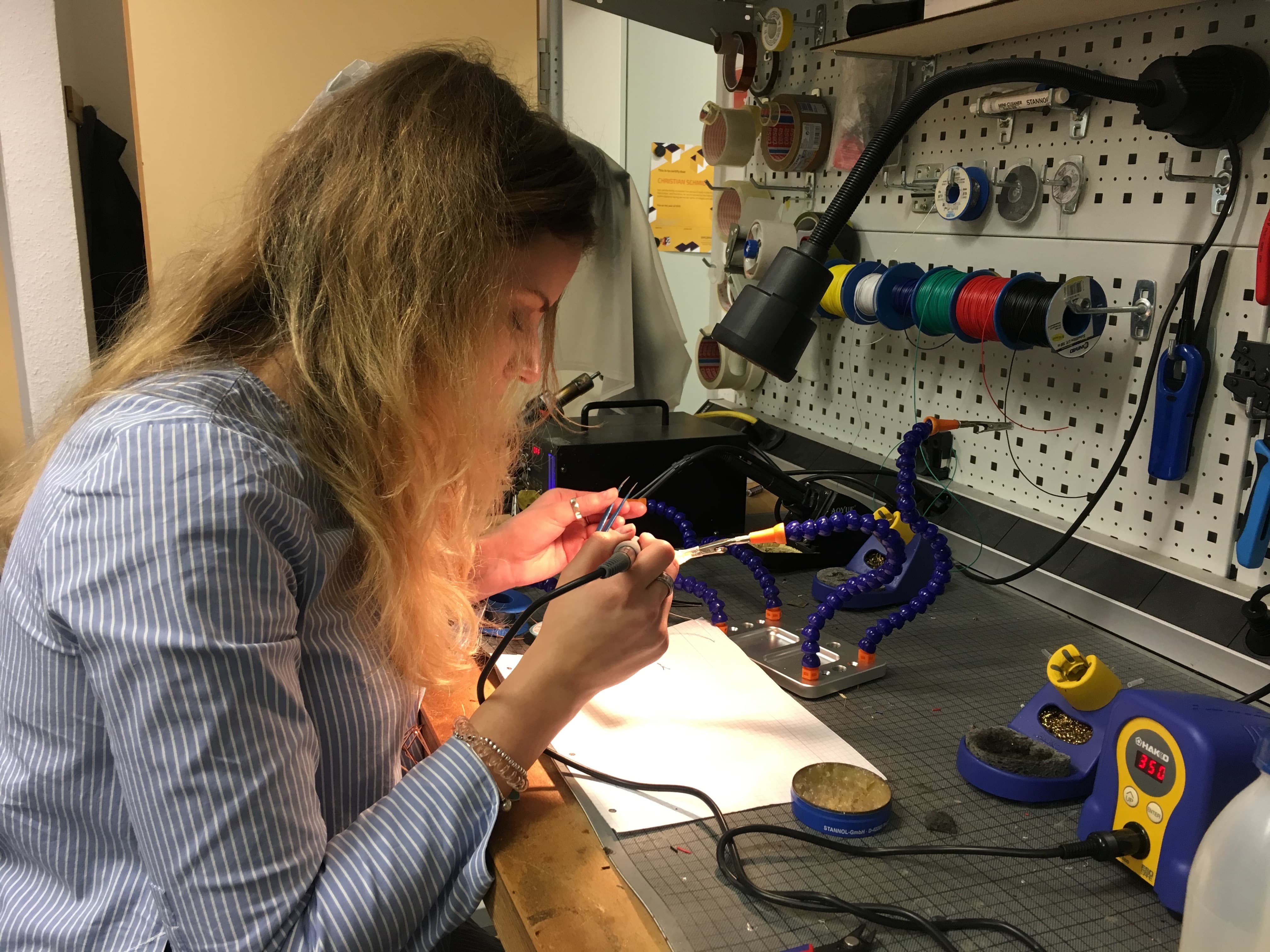
Soldering
I collected all the needed components from the FabLab drawers:- 1 x Attiny 44
- 1 x 10mF SMD Capacitor
- 2 x 10kΩ SMD Resistor
- 1 x 470Ω SMD Resistor
- 1 x blue SMD LED
- 2 x 3 SMD Pinheader
- 1 x 6 THT Pinheader
- 1 x SMD button
So, I did the soldering:
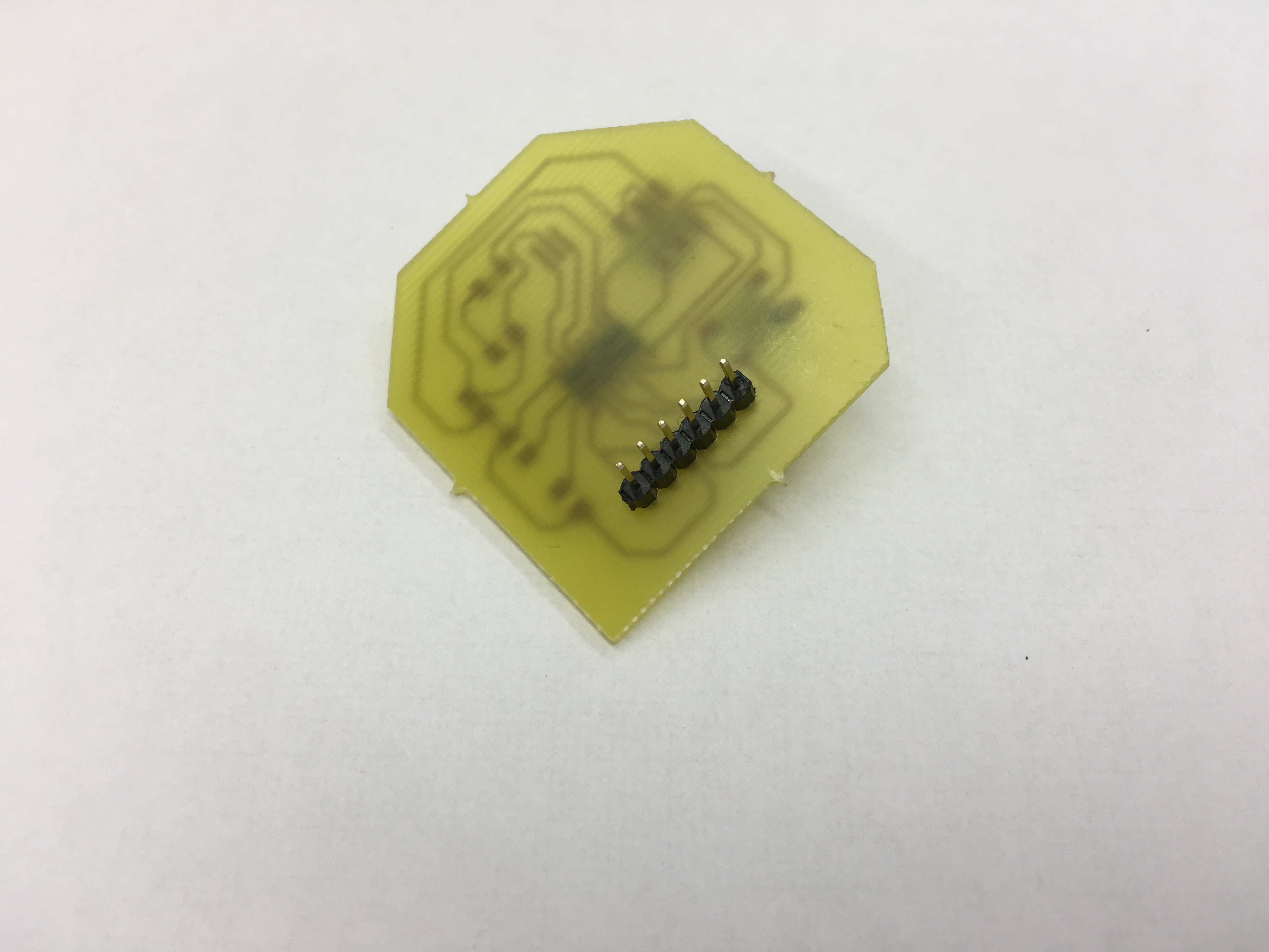
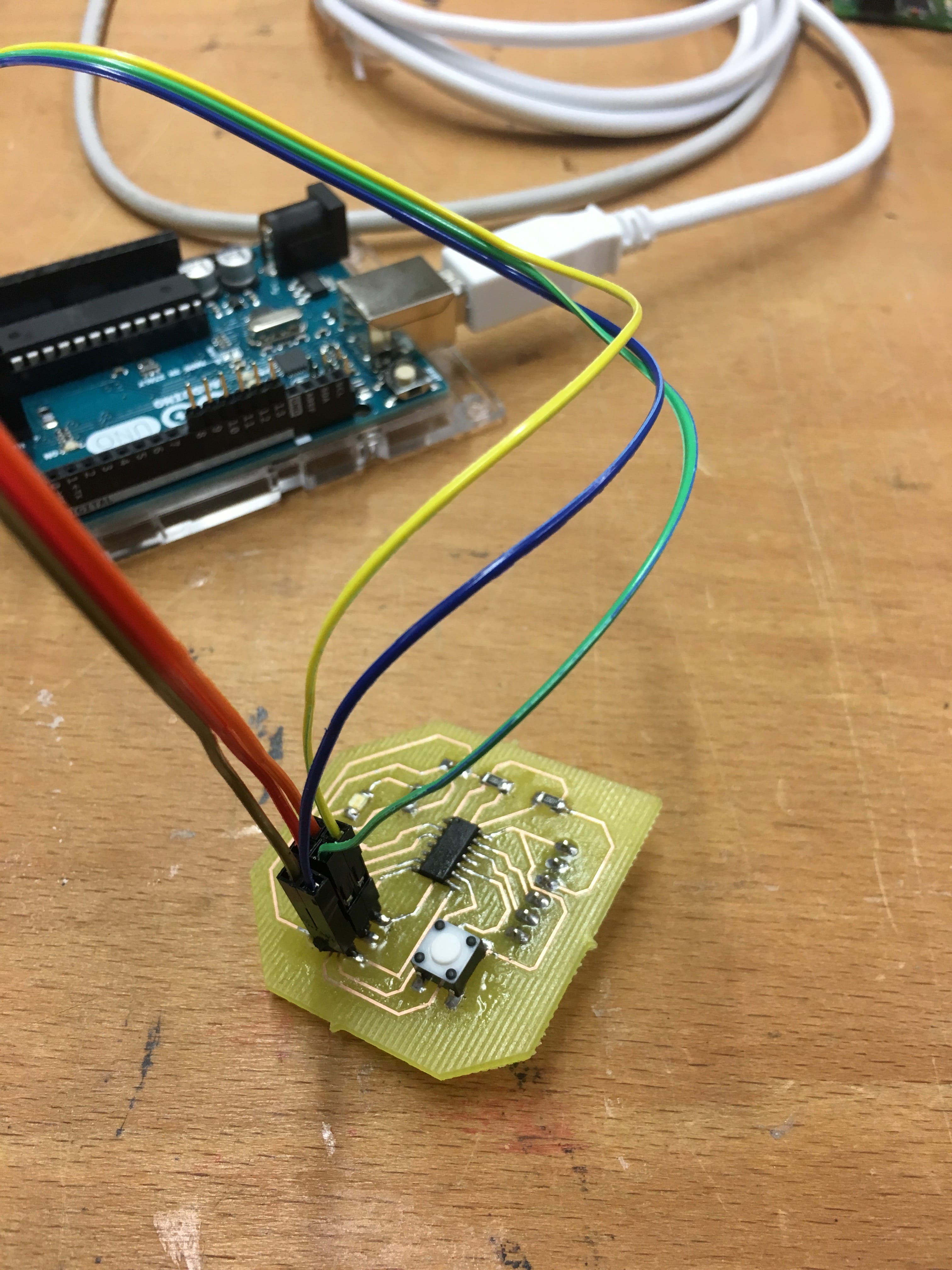
After Soldering all parts together I got this:

At that moment our FabLab ran out from 20Mhz Resonator (which I should use for hello world board). That is why for programming I used Internal Clock of Attiny44. But still, I will have experience with external resonator. For more details about that please check my Final project documentation.
And then connected it to the computer via ArduinoUno to check, if it works:
P.S. I also connected it using FabIsp from Electronics production week. For more details about that please check Embedded Programming week.