Setup
| Softwares | Fonction |
|---|---|
| Silhouette | Communication with Silhouette Vinyl-cutter |
| Corel Draw | Communication with Laser-cutter |
Skills acquired
Asssesment validation
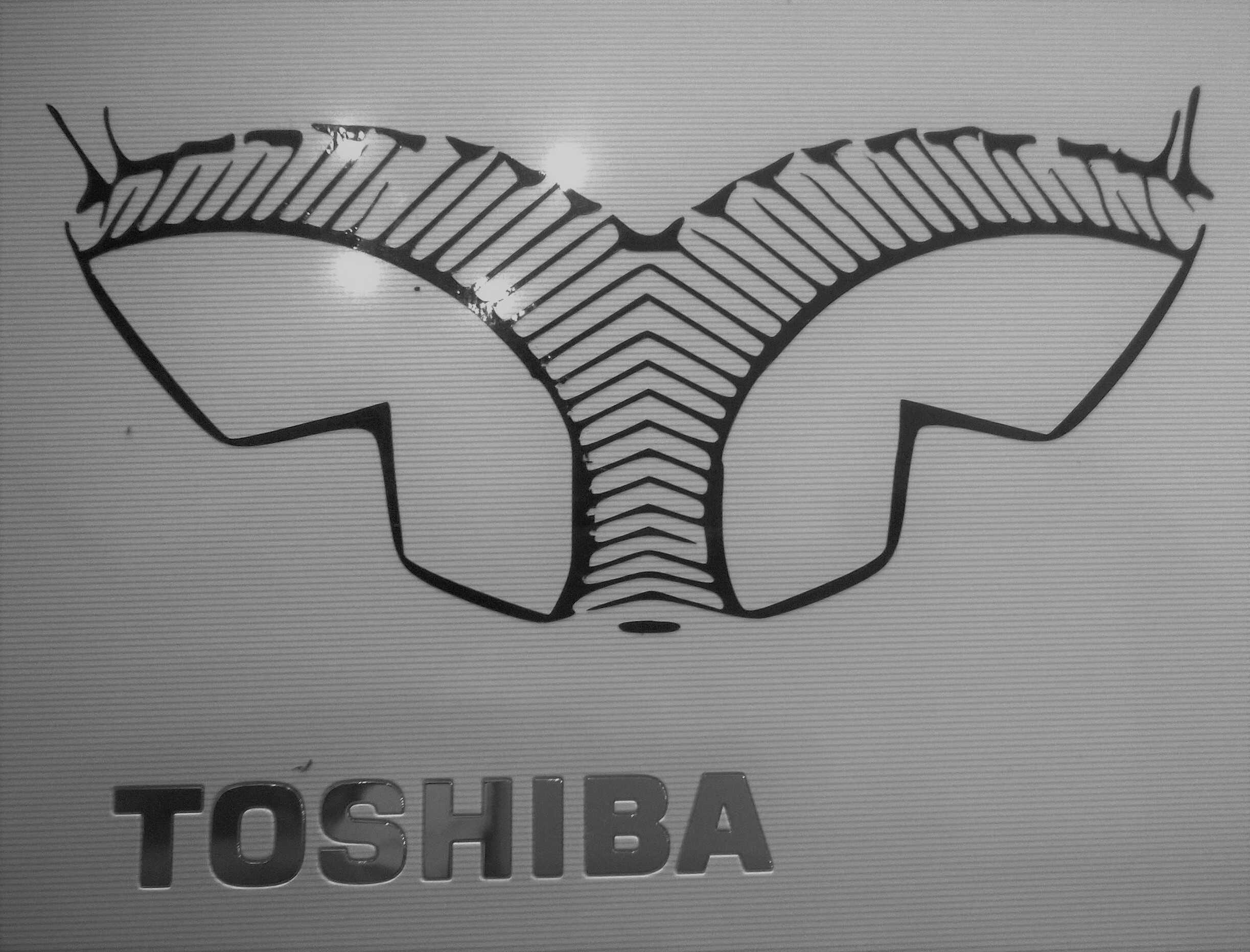
The first assignement was to create a sticker with a vinyl cutter. Its design should be tailored and not copy-pasted from the Internet. I thought about doing a stencil based on a photograph. A dedicated website, Stencilgram provides this computation. It is also possible to do it on Gimp as shown on this video . I tried with several pictures but they are often too many contours. The ideal pic would have a lot of contrast and clear shapes. The best would be to create a picture for this purpose. A kind of photogram in a way. My first try was with a contrasted picture of stairs. I vectorised a part of its stencil on Silhouette. I then tested different parameters to cut it, varying speed and thickness. The results were uneven, either the vinyl wasn't cut through or some parts were ripped off. The fine details could be to blame. After inspection the blade showed signs of blunt. Future tries will hopefully lead to a nice sticking stencil.
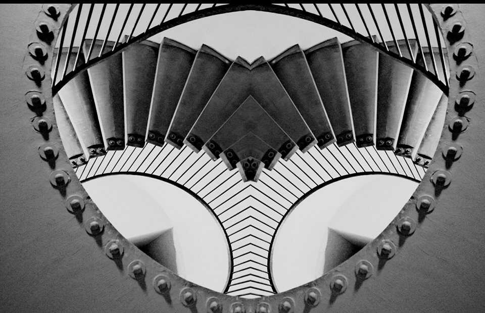
original image
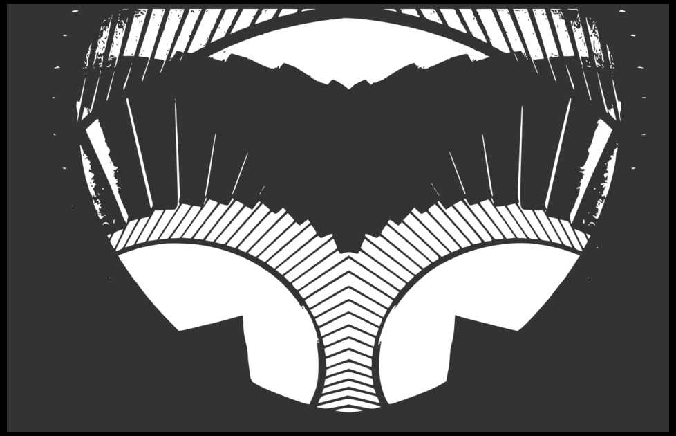
stencil made with Stencilgram
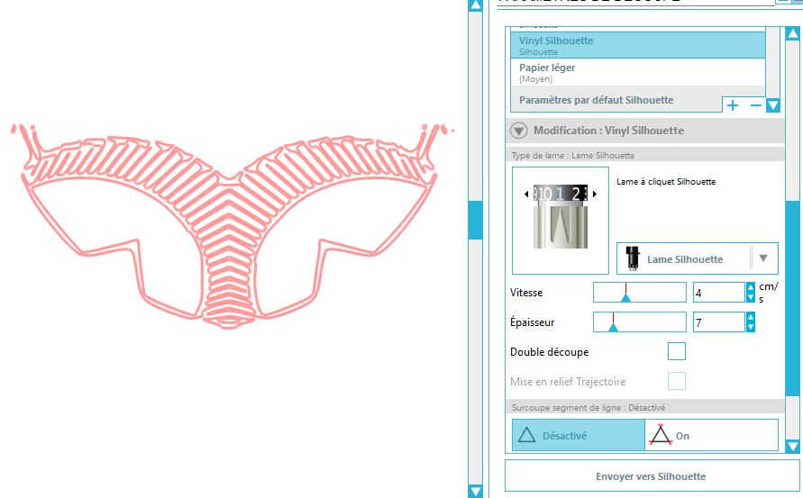
vectorized stencil with Silhouette
WoMa bought us a brand new blade and a brand new cutting mat for the vinyl machine. And a lot of issues vanished.
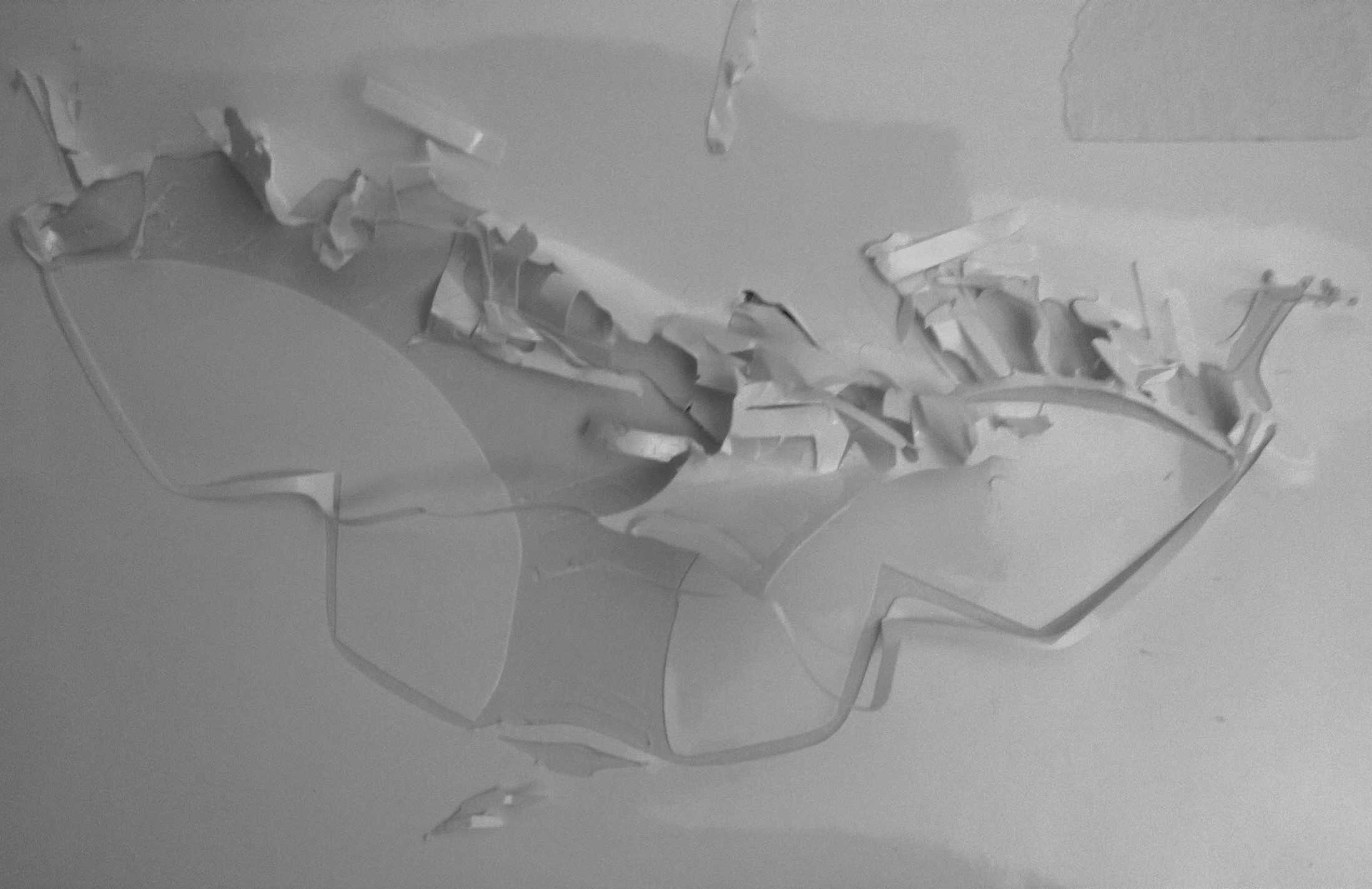
first try
final vinyl
I then redid the same workflow but, this time, with a stencil made with Gimp
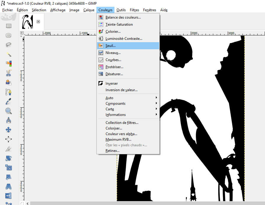
in Gimp stencil can be made playing with Thresholds
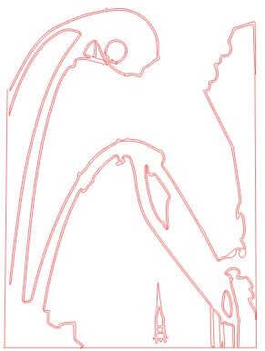
vectorized -notice the double lines
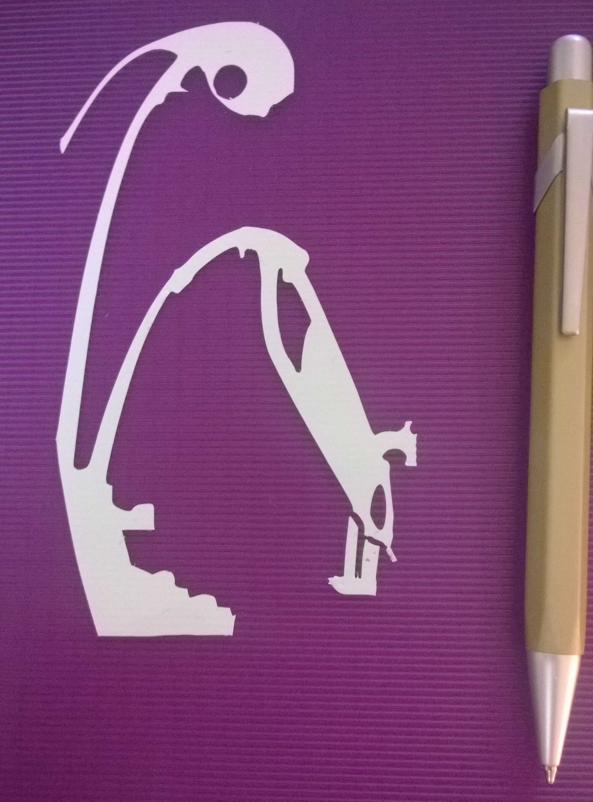
sticker derived from a picture via Gimp
I noticed that the vector had double contours and on some sides it did not get closure. That why I closed it manually on 3 sides (visible at the single lines). This double lining can be prevented when vectorising the picture by playing with the parameter Scale.
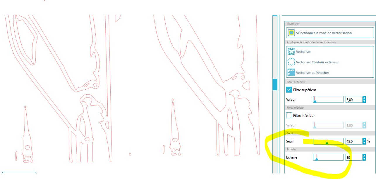
Playing with the Scale parameters (10 on the left vs. 21 on the right)
I then made a sticker out of a quick Inkscape drawing. This design can relate to my final project, a collector of footsteps energy.
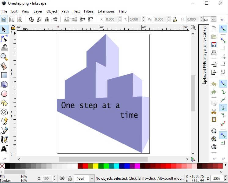
Inkscape design
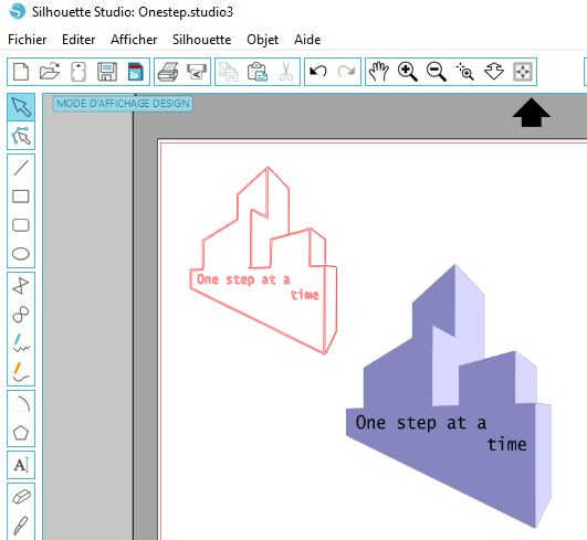
Silhouette vectorizing
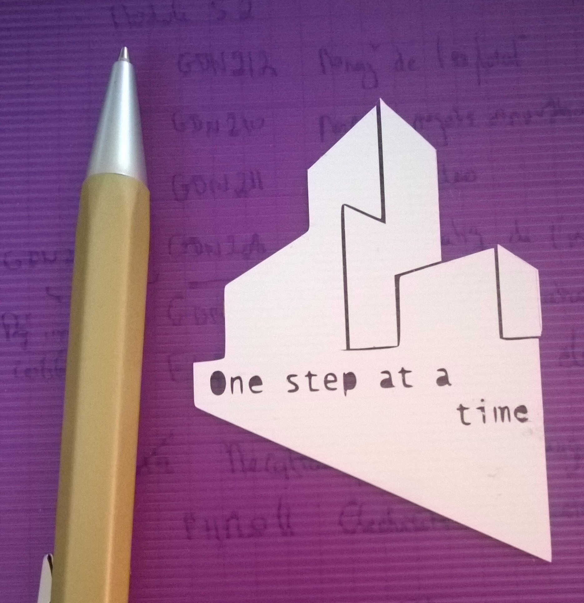
sticker derived from an Inkscape sketch
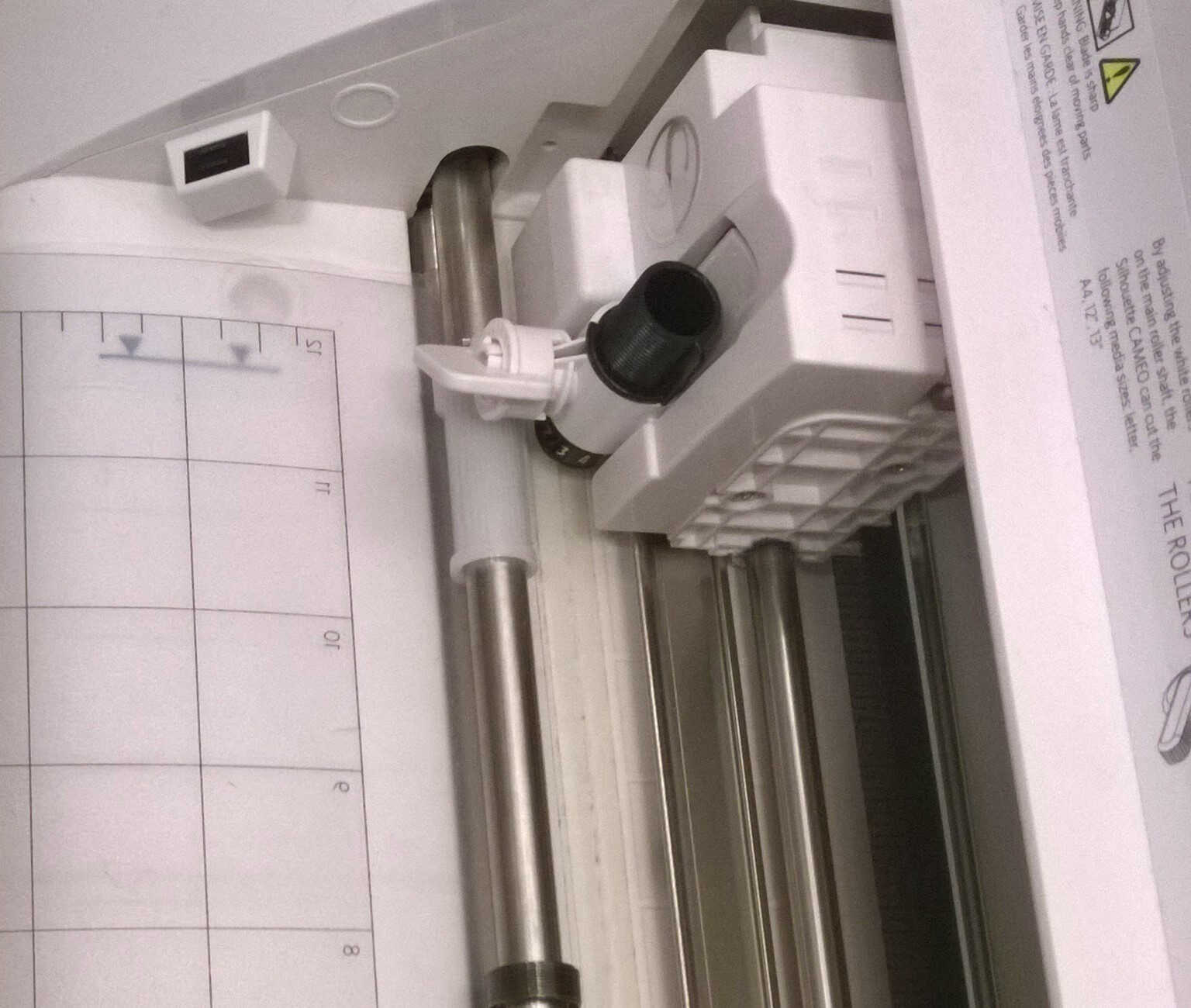
The cutting was made with a Cameo Silhouette.
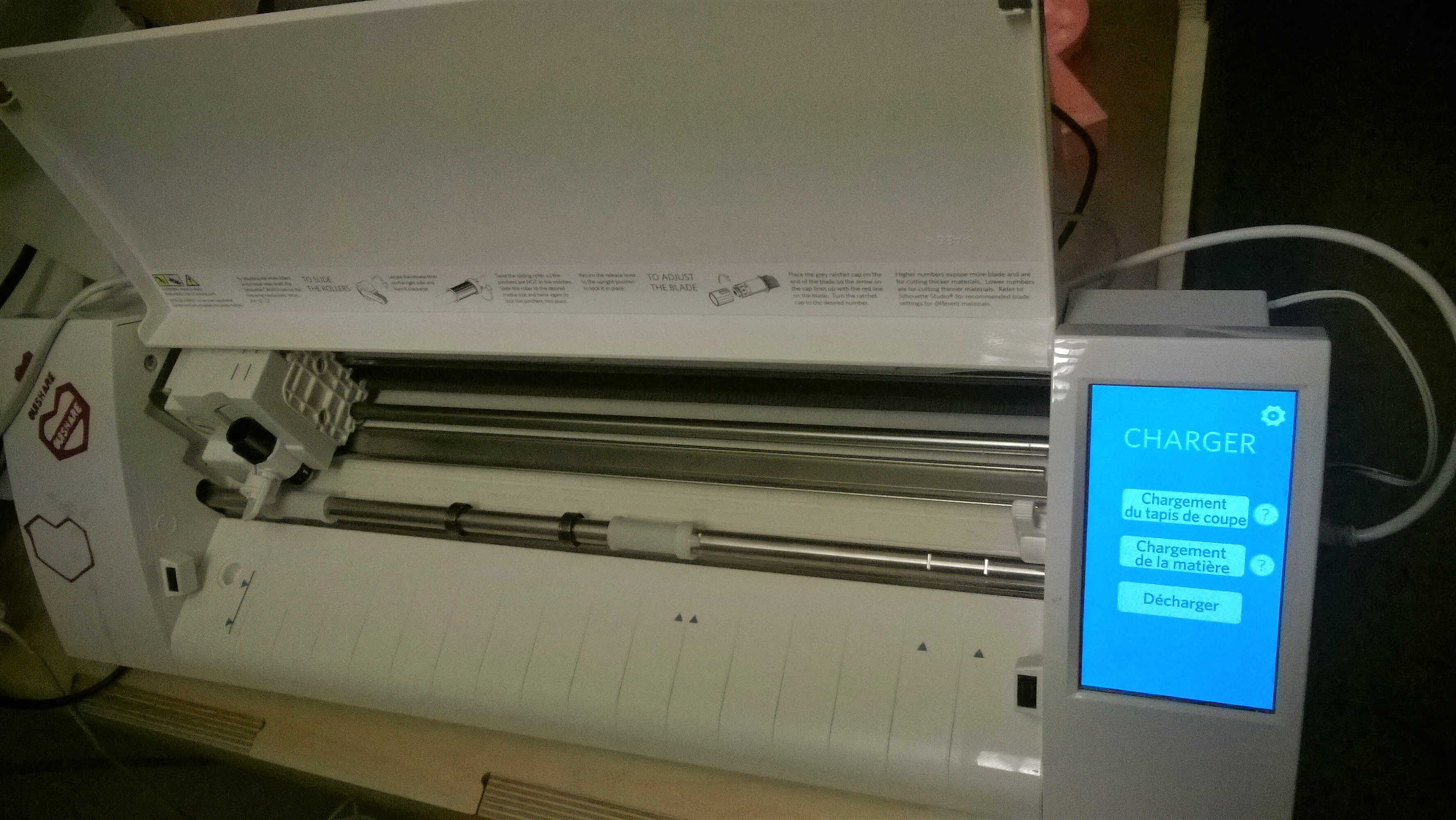
Cameo's belly
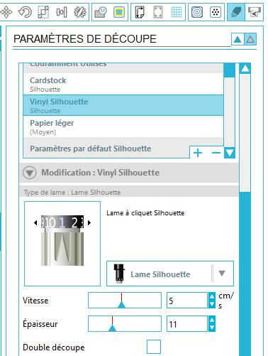
Cutting parameters
The cutting parameters used were the ones advised for Vinyl Silhouette paper (Blade grade 1, speed = 5 cm/s and depth = 11). The blade grade was checked and the mat charged.
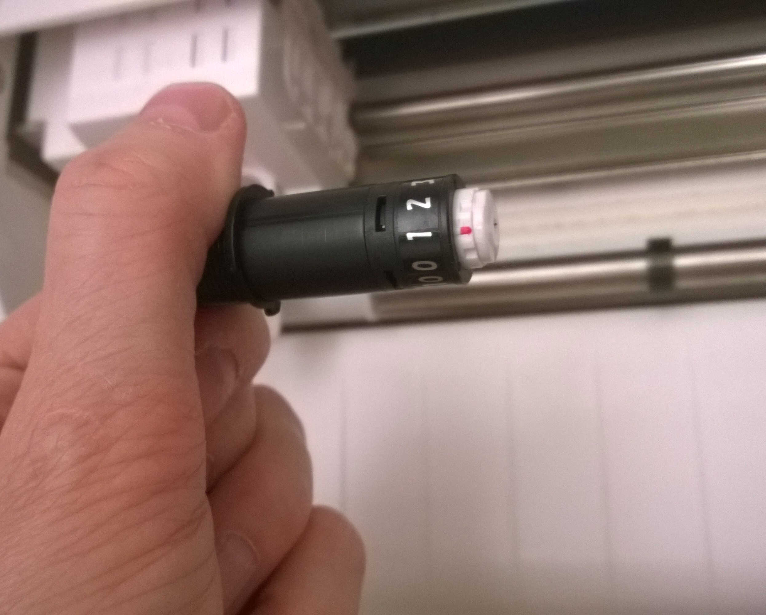
Checking the size length
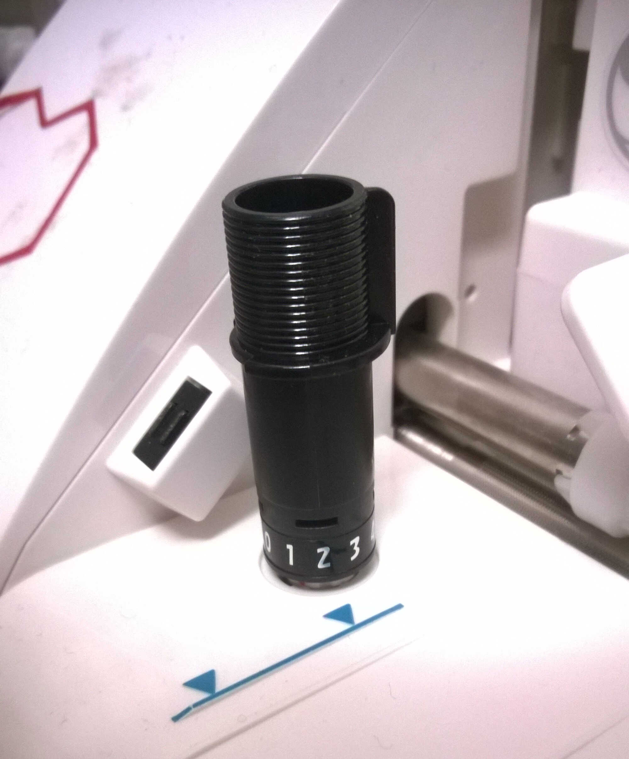
Modifying the blade length
charging the mat -here empty
To place the stickers transfer paper was used. It is a delicate task to remove the tiniest details. A cutter blade can be of great help.
Source file to load here
The design for this week was made with Fusion 360. As a group we looked at Press fit kit on Pinterest for inspiration.
We found an easy-to-make pen holder. We decided to split in 2 subgroups to compare parametric softwares. Yassine and Isabella used the Rhino-Grasshopper combo.
I turned to Fusion 360 as I saw some assembly/simulation/animation possibilities.
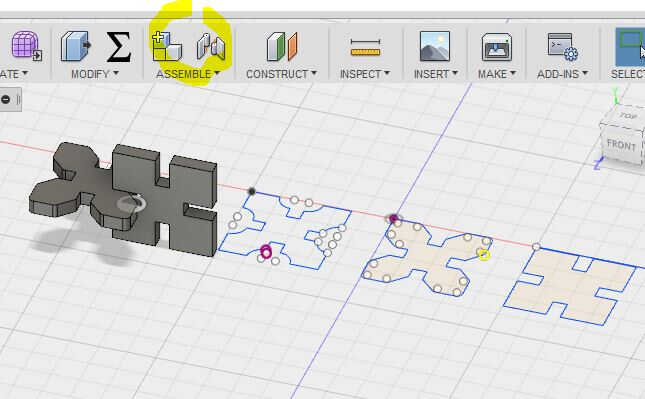
With this design the different layers are mostly variations of the same layer.
I planned to do a sketch, to extrude a layer out of it, to copy it, to place it above the previous one and to modify the last one looking at the composition from above.
It turned out not to be compatible with Fusion's philosophy. The modifications cannot be done on bodies only on sketches.
I did not succeed (I now know how) in stacking the sketches so I ranked them one next to the other. the copy paste routine is not intuitive.
The edit sketch mode need to be on to copy/paste a sketch.
In order to introduce variations, I added angle constraints and played with them.
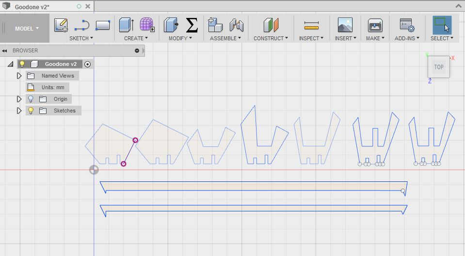
layer by layer sketches
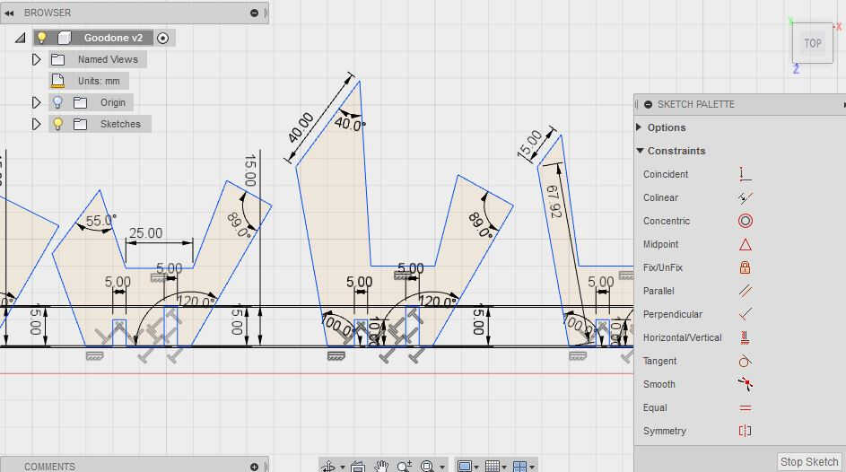
the constraints added (perpendicularity, angles, dimensions)
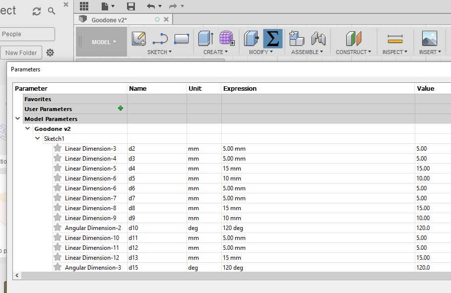
the parameters table -values to be replaced by side name
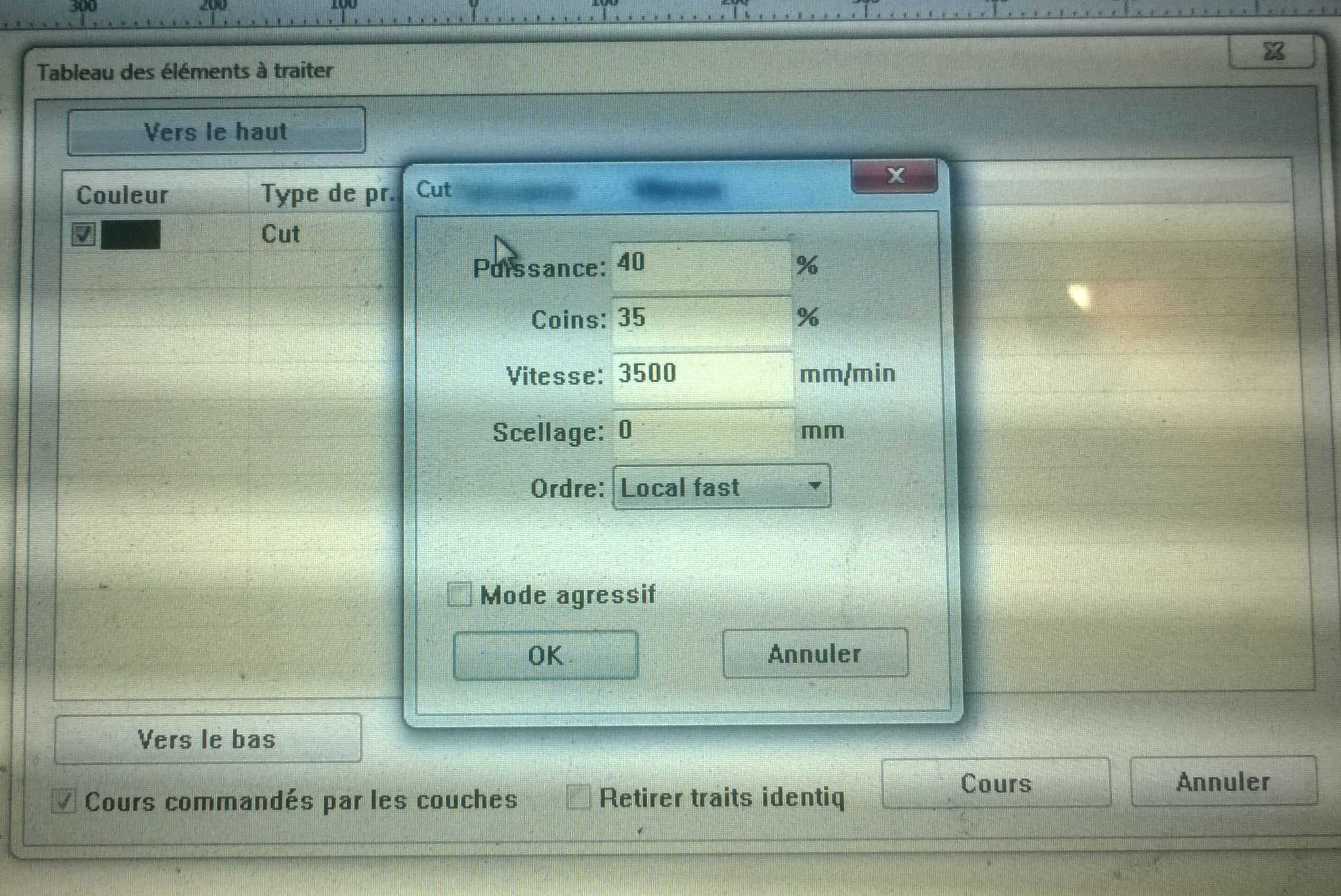
Cutting parameters -as speed is reduced at the angles so should the power
The design was cut from a cardboard lightly thicker than 5mm. With this first laser-cutting test, I was quite satisfised with the result. My design was less elaborated than Yassine's and Isabella's who played with smooth surface and projected intersections in 2D. Nevertheless it took me a third of the time it took them. I also appreciate the compartements I added in mine. As I did not use the same cardboard material-mine was slightly thicker-, my layers fit a bit better. Hence Fusion 360 is a good tool for quick prototyping.
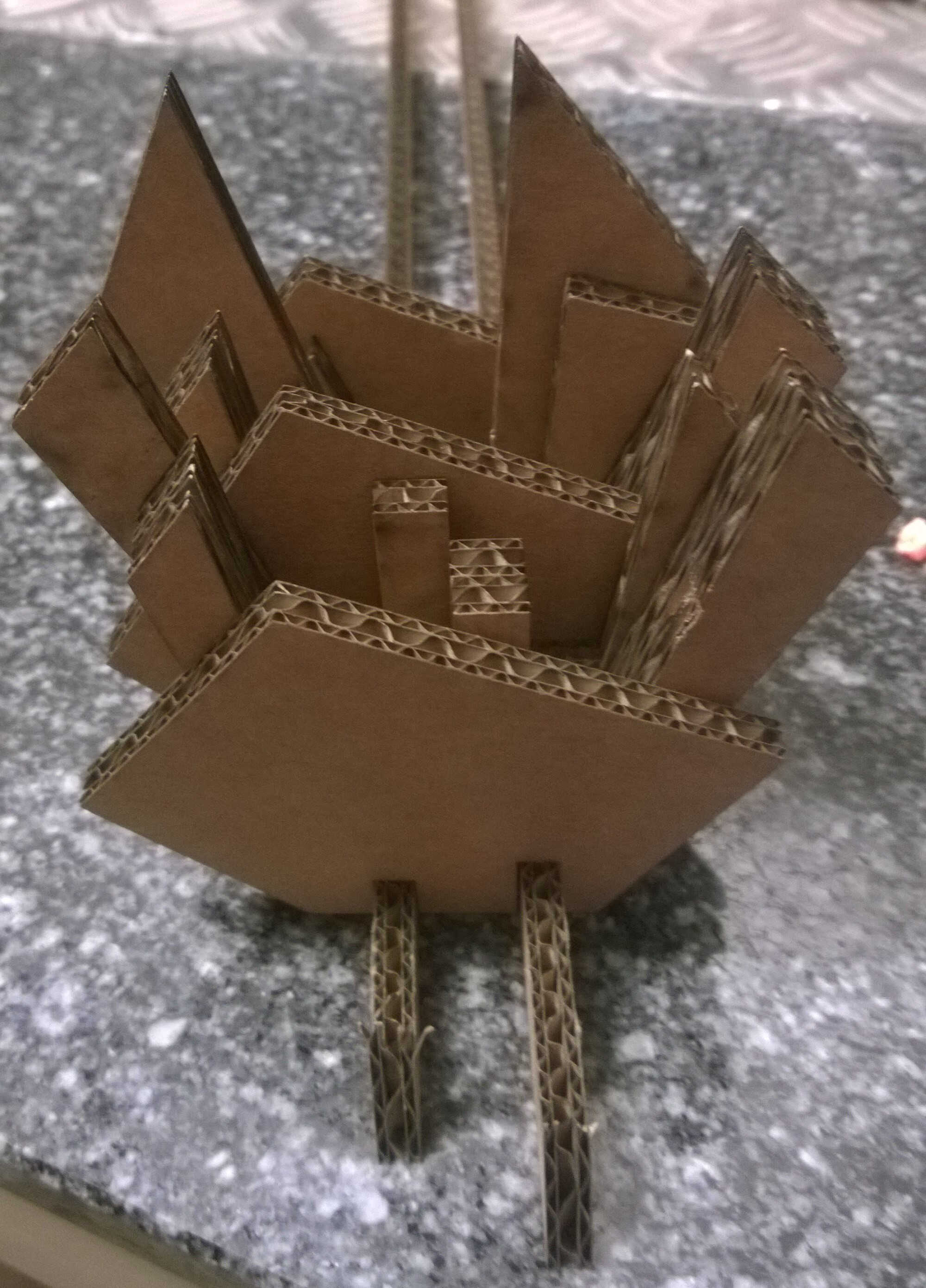
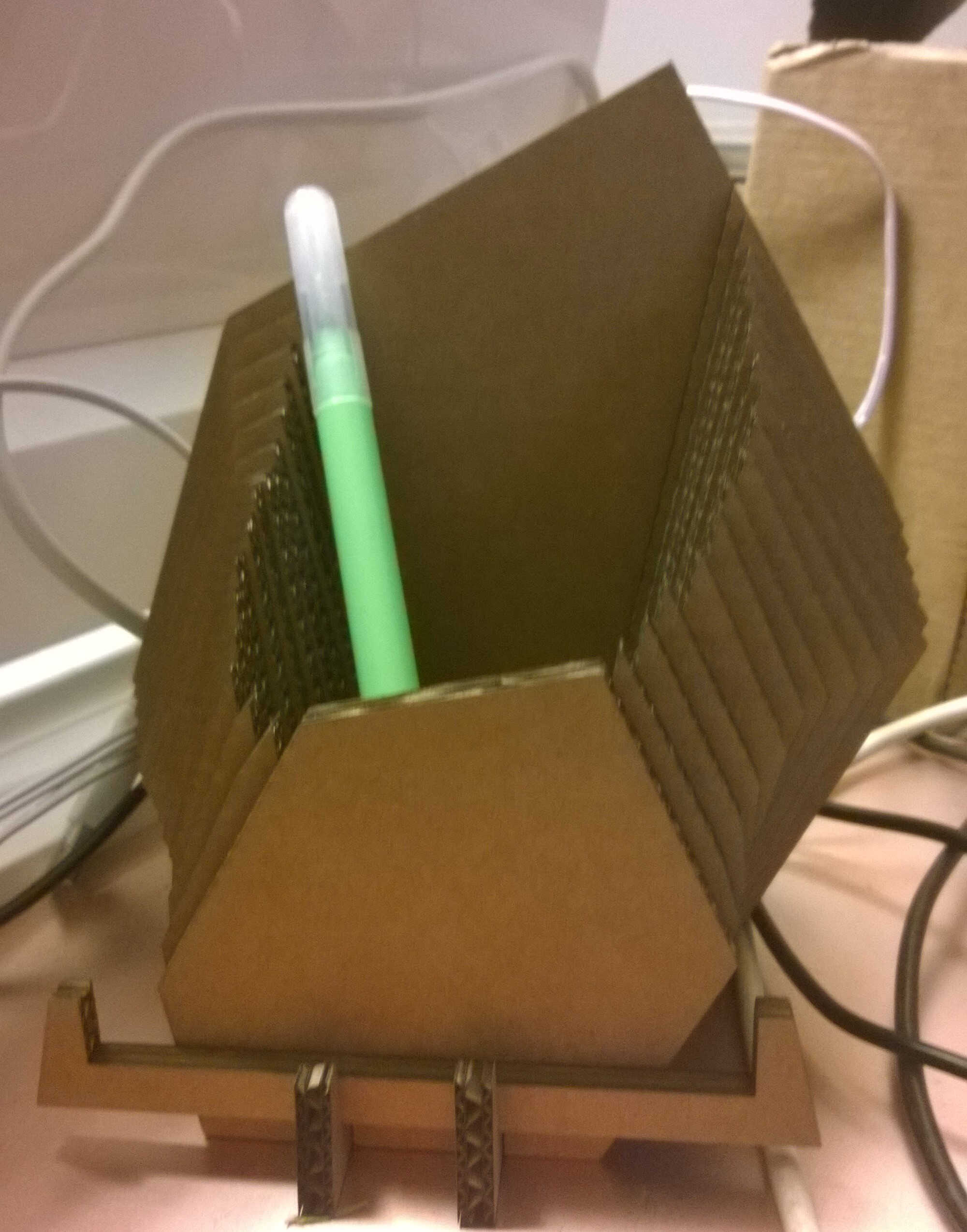
the assembled pen-holder -notice an oversized base
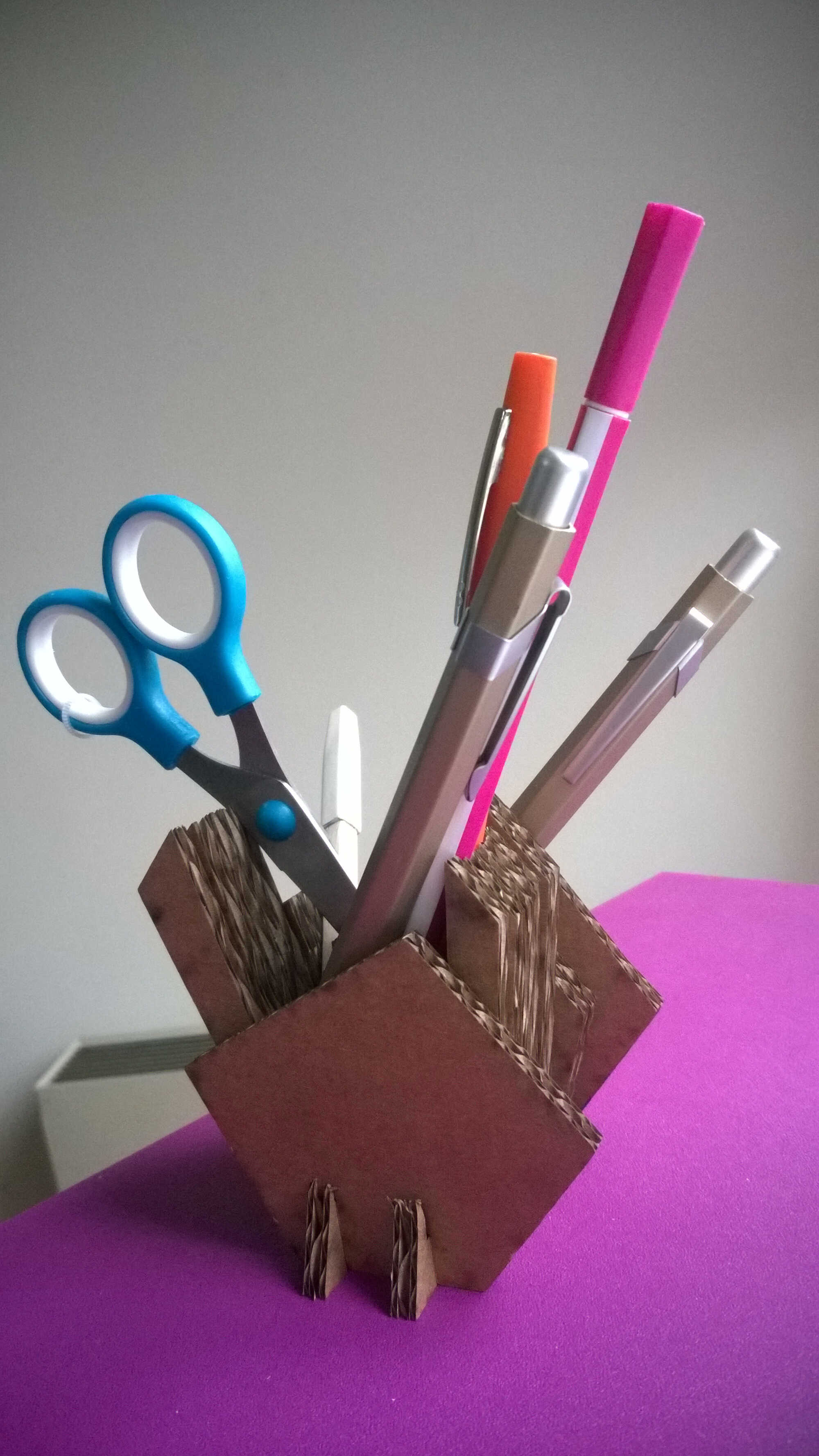
pens actually stick in it -the cavities could have been deeper
Yassine's and Isabella's
Source file to load here
The laser-cutter is a xxx PC 10/80KII, a CO2 laser cutter. The bed dimensions are xxxx. In order to use it, it has to be switched on -switch on the right side. Then the cooling system has to be powered on. Last the venting system has to be activated to filter the fumes with actived coal. As it makes a lot of noise we wait until the last moment to do that.
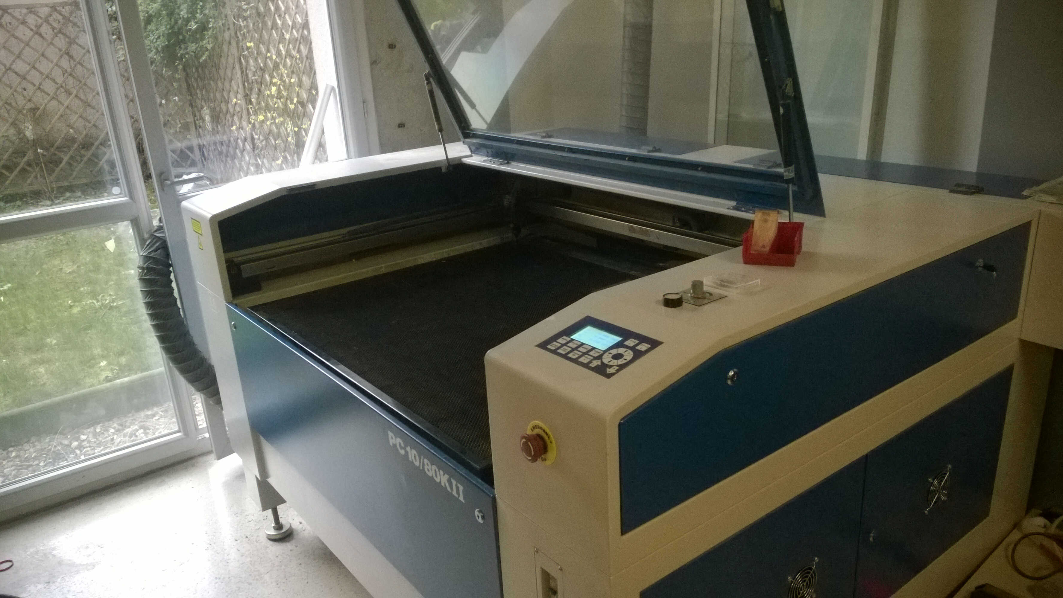
WoMa's laser cutter: name+dimensions
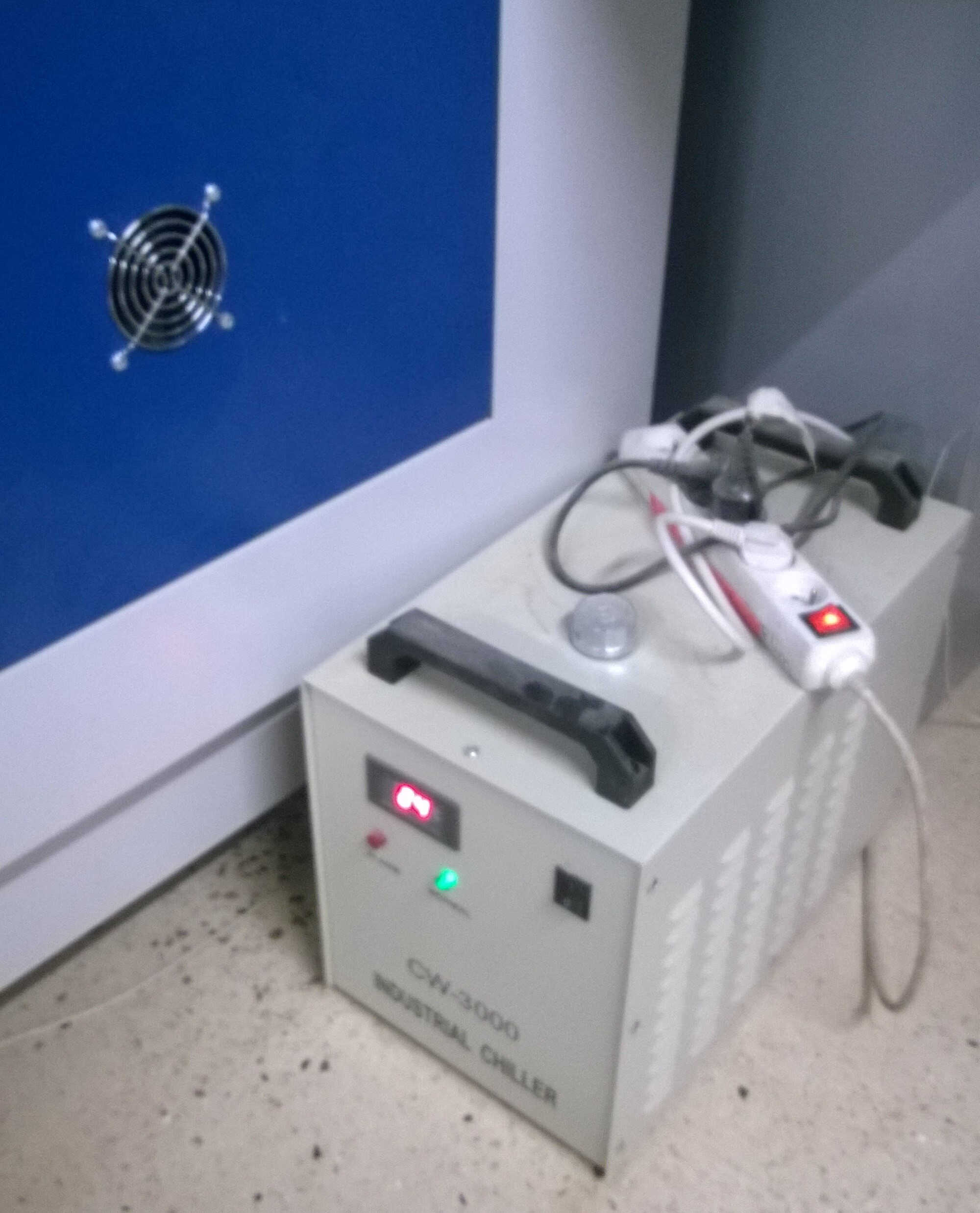
water cooling system, quieter than a air one
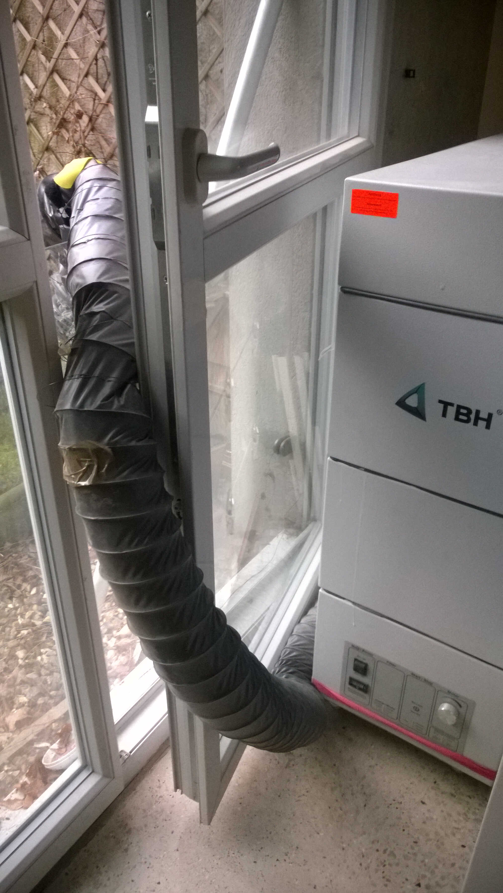
venting system, to exhaust fumes
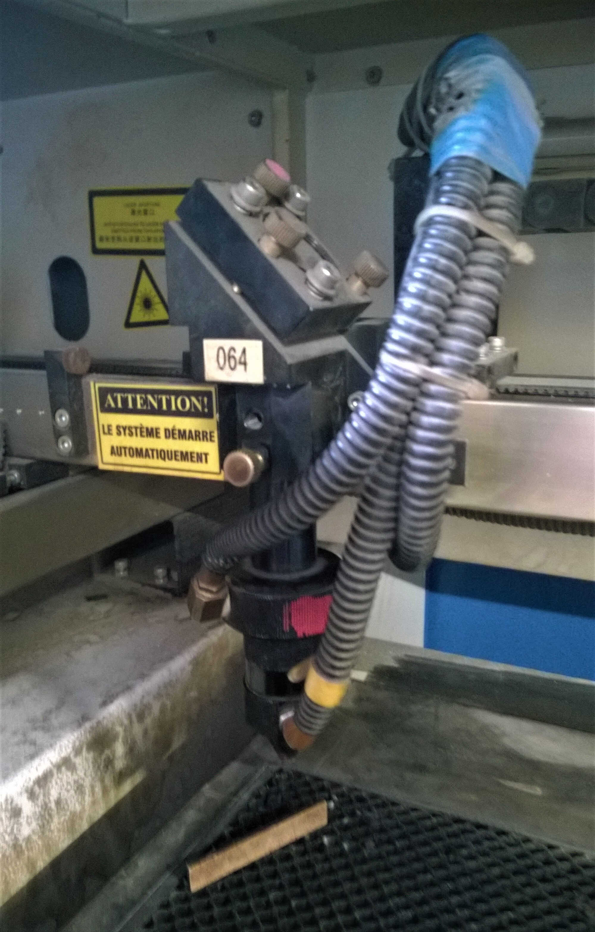
Laser focus
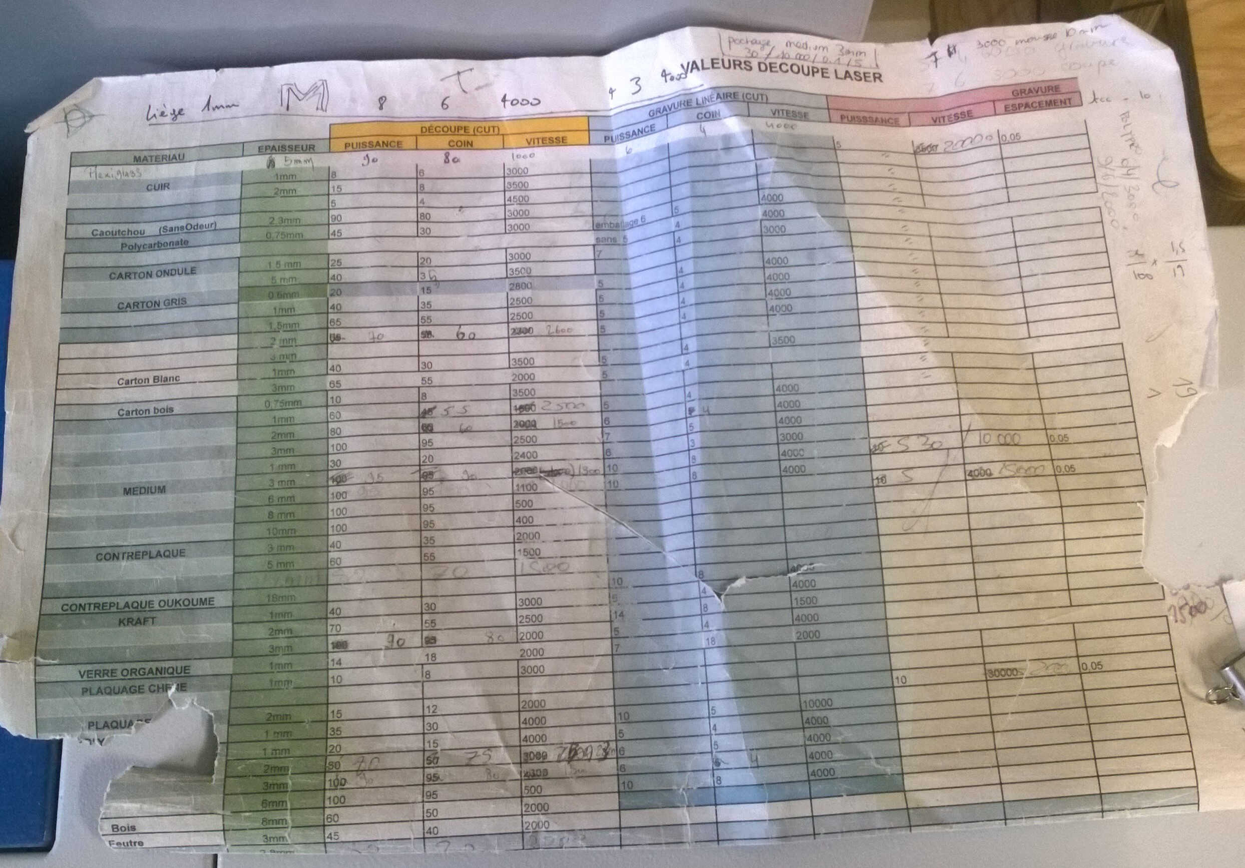
Parameters guide
The design is saved as .dxf, loaded in the laser cutter computer and opened in Core Draw.
A plugin enables the connection between this computer and the laser cutter.
The plugin enables the setting of cutting parameters such as power and/or speed and computes the cutting trajectory.
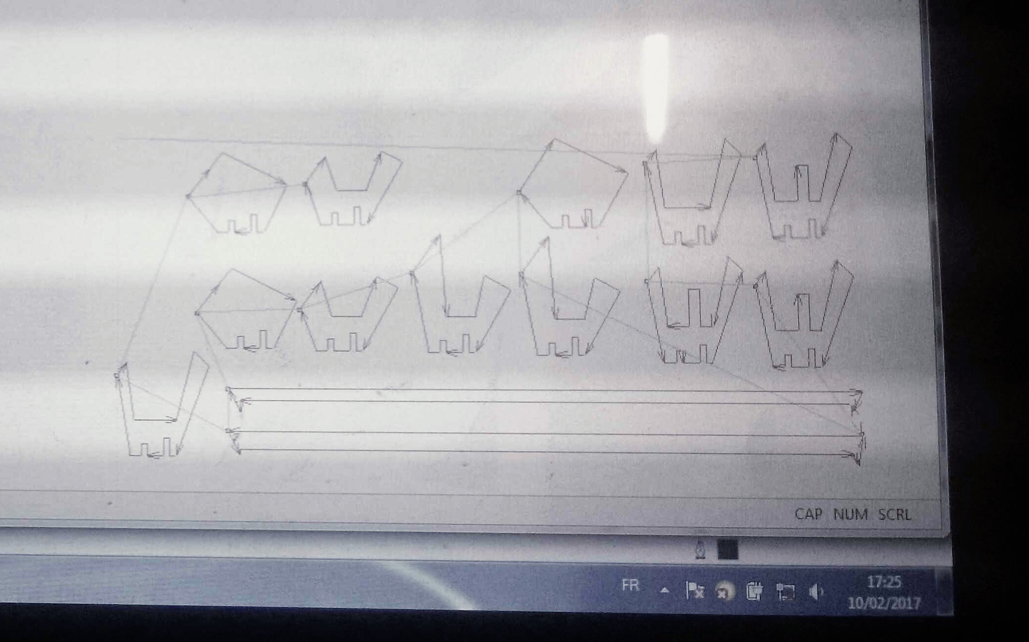
At this step it is important to stipulate the origin location (yellow ensemble). Here I chose top left. The cutting trajectory is then televersed on the laser-cutter (green arrow button). It can be retrieved from the laser-cutting machine by pressing simulataneously Run/Pause/Delete and Home. In order to define the origin of the laser head, the z is defined by putting a gauge between the material to cut and the laser. Once Z > 0 is pressed to save this position.
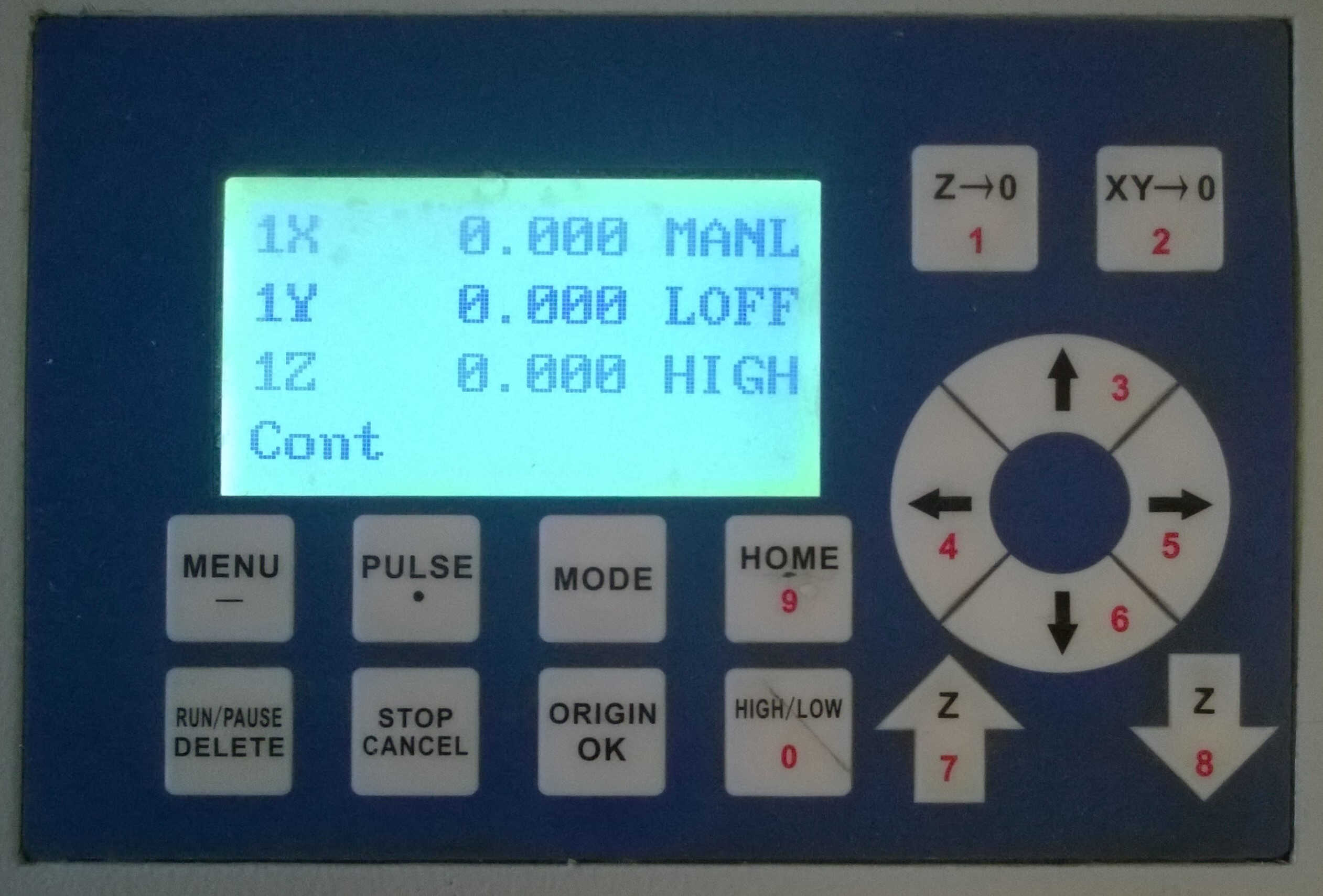
| Key | Fonction |
|---|---|
| Run/Pause/Delete + Home | Retrieve file |
| Home | Laser goes to home position |
| Z -> 0 | Defines new z0 |
| XY -> 0 | Defines new x0 and y0 |
| High/low | Defines the displacement speed of the laser head |
Chamfers and joints
Before creating my press and fit kit, i did some practice, reproducing notions (chamfer and joint type) mentionned in the lecture. As for the joints I am not quite sure that it was the design Neil was talking about.
chamfer
joints
assembled joints
Assembly, animation and simulation
When modelling the chamfer variations I tried to use another Fusion functionnality: Assemble. To do so the bodies need to be upgraded to components. Once it's done I used the Join option. Join enables to define relative positions and allowed displacements.
assemble
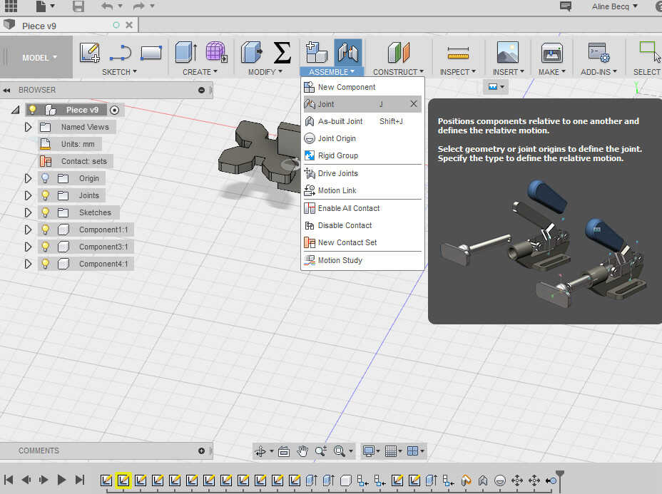
relative positions
Once joint the components can be animated.
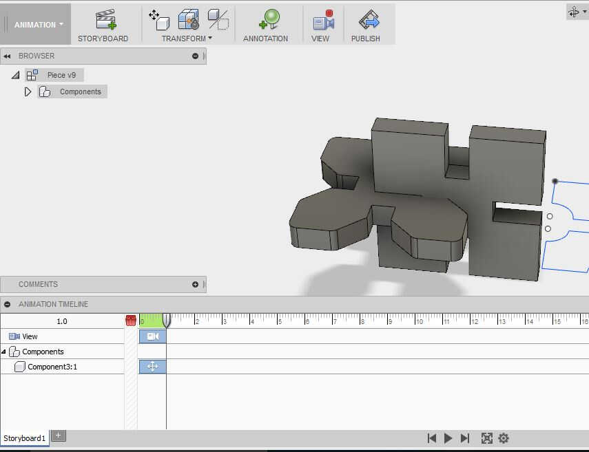
animation storyboard
I tested one other functionality: the static stress simulation. It consists in defining the materials of the bodies, the structural constraints (the anchor points of the strcuture for example) and the load stresses. Here I set a 5 N force on the horizontal piece.
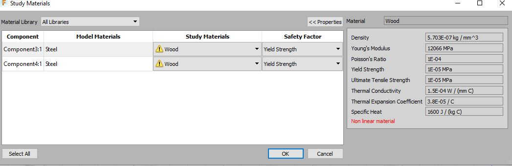
materials definition
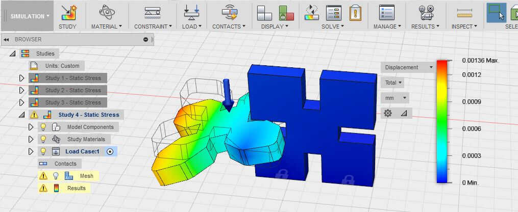
static stress simulation results
The major issue I faced on the simulation side was related to its static aspect. I was picturing a dynamic simulation. One which could compute the stress around the slot when the pieces are pressed one in another. For my final project I would like to be able to compute stress caused by walking on my energetic pavements-the stress causing components displacements.
Thickness test
Tests were made to see the limits of cardboard and wood materials. Slots were designed so that sections of 10-8-6-4-2-1 mm were isolated. The strips of 2 and 1 mm show flexure when stress is applied.
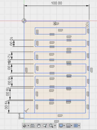
Fusion 360 design
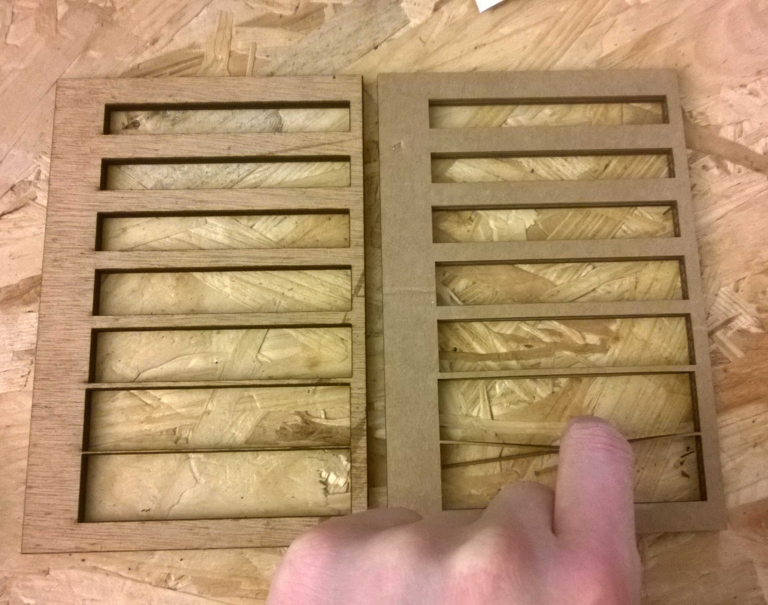
5mm thick wood (l) and cardboard(r)
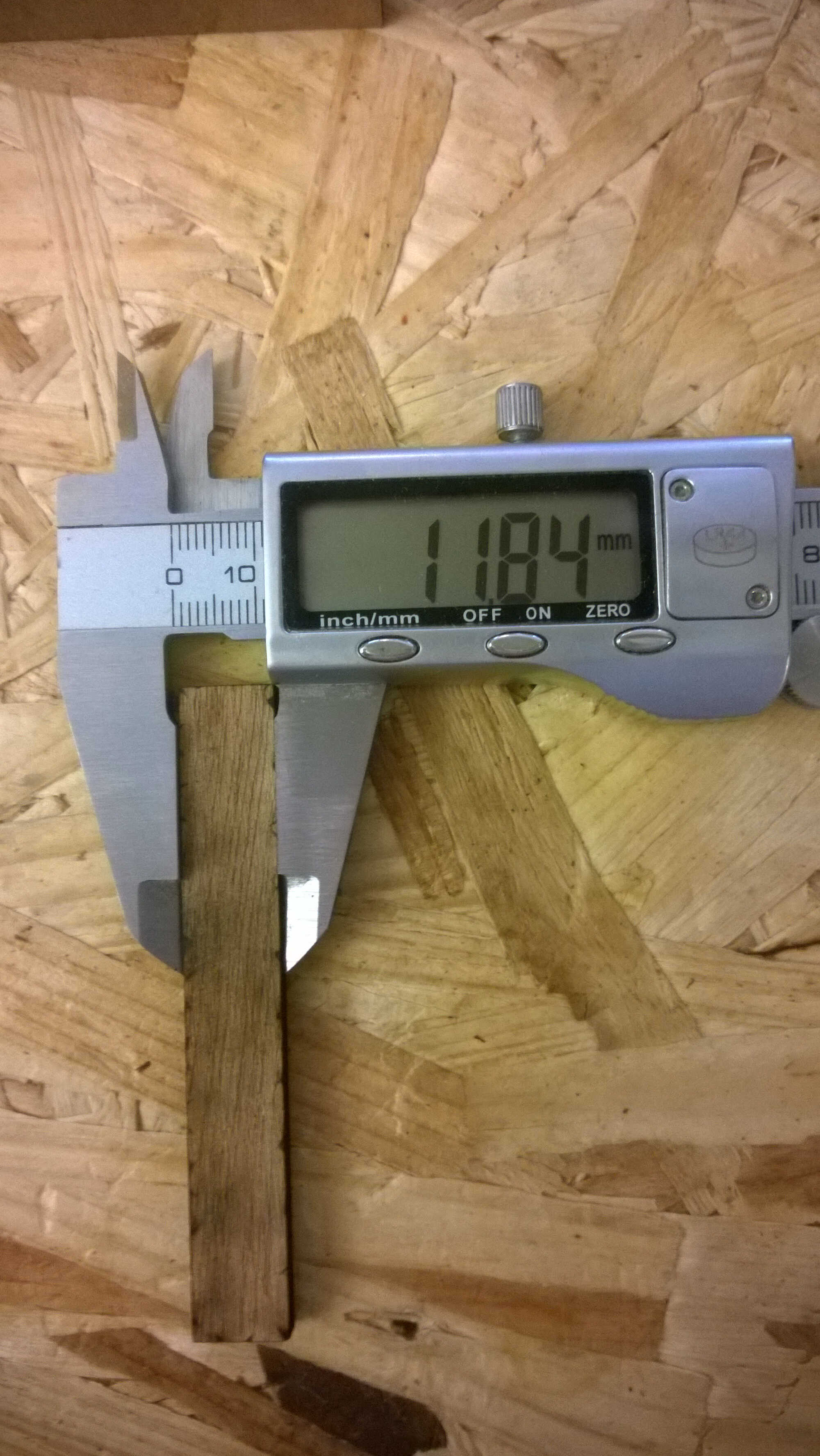
0.16 mm kerf in Fusion
The cut parts were used to check the dimension coherence. Divergence were acknowledged-above in cardboard as much as 0.16 mm were missing. This is probably imputable to kerf. A kerf ranges can be found on this website . The next prints should take this into account.
Source file to load here
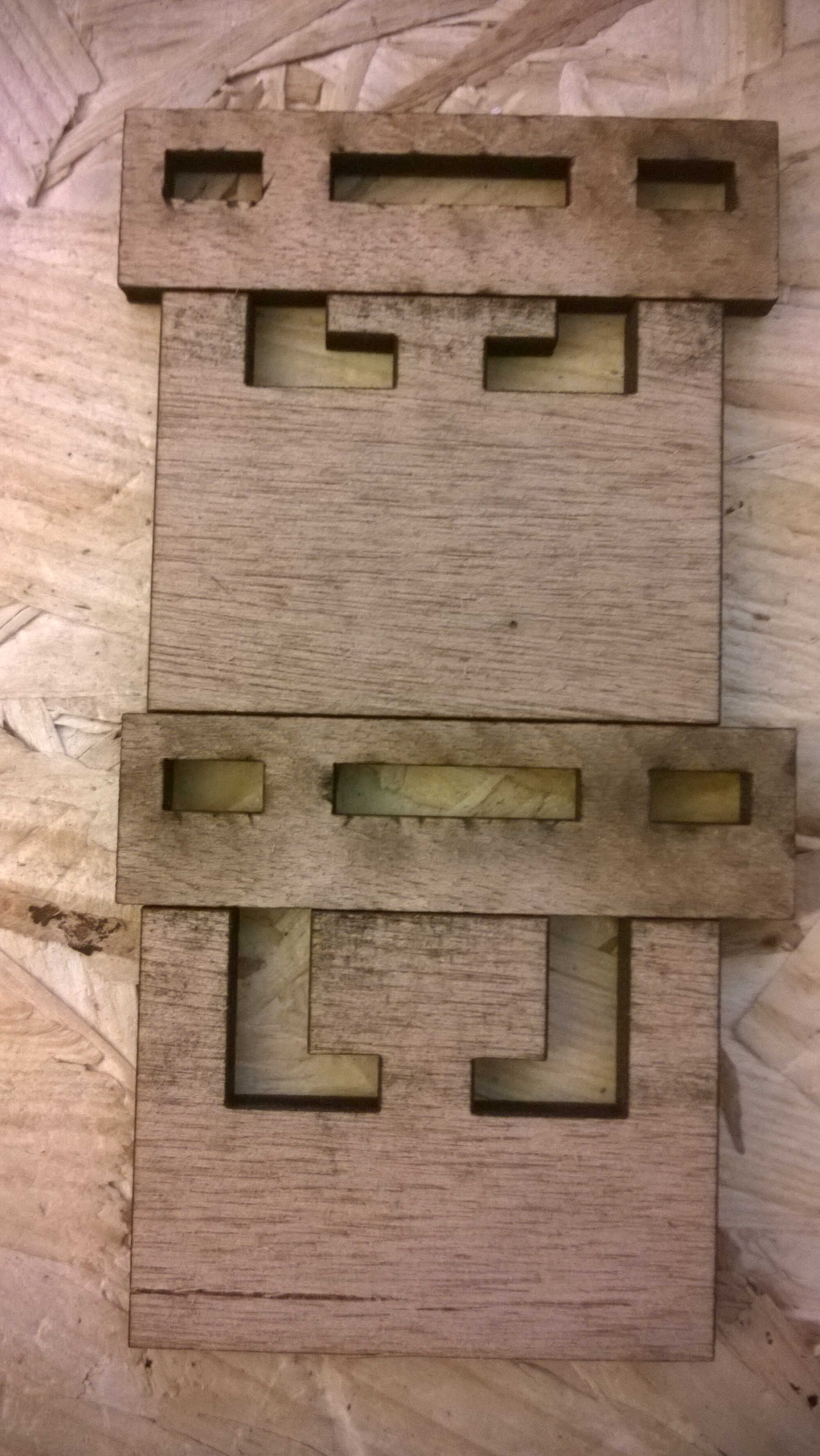
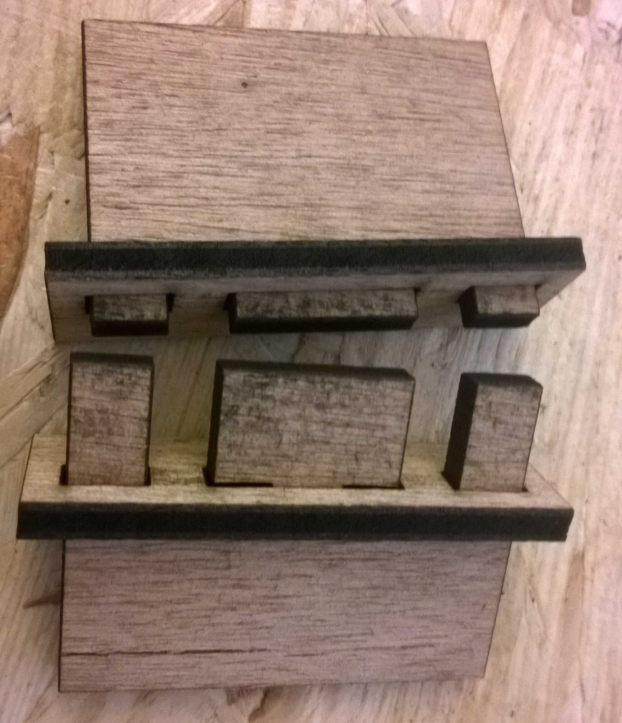
Joinery
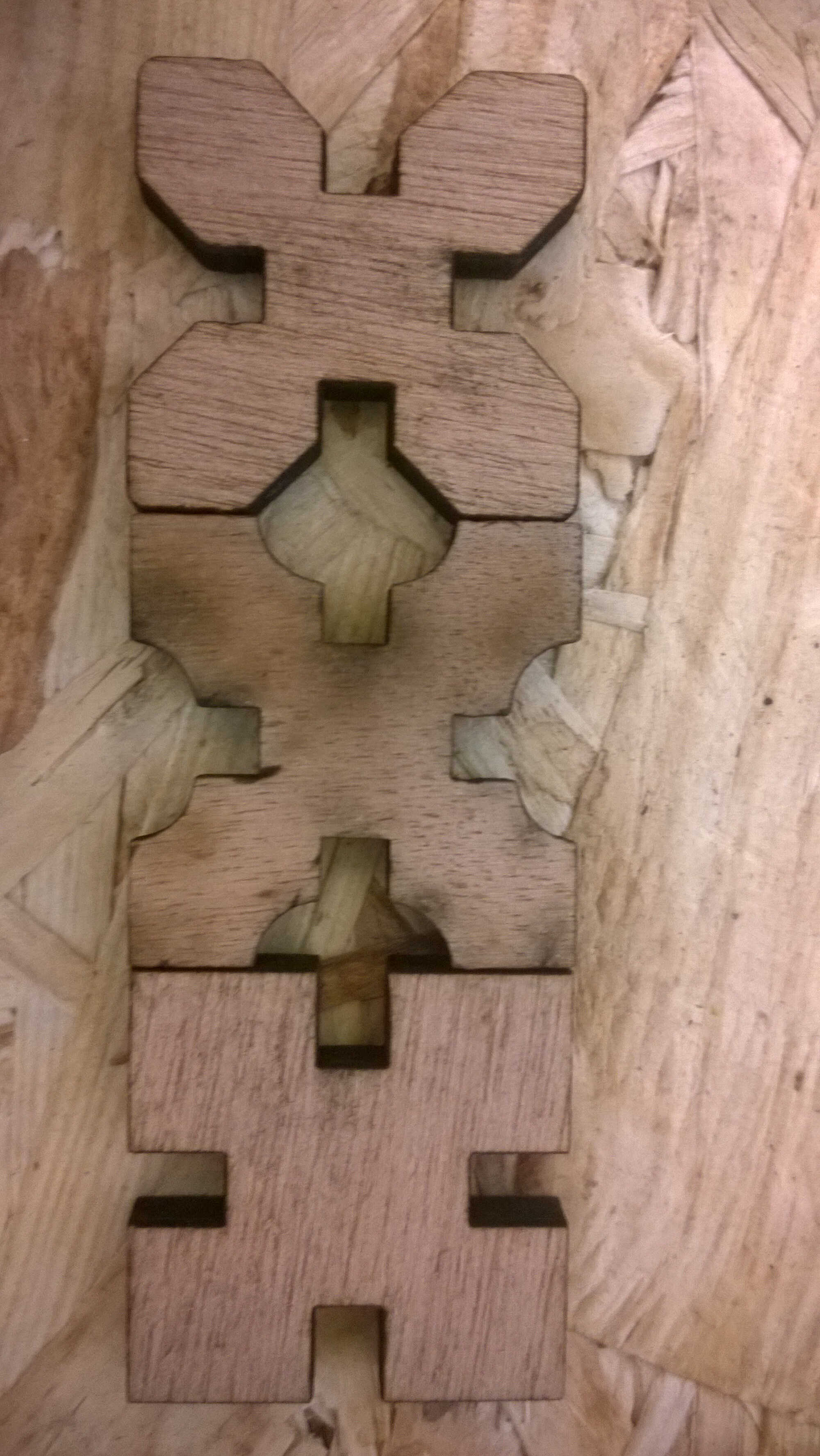
As a last test I wanted to test a design based on japanese joinery. I found the design on Pinterest. This is no proper press and fit but provides inspiration for assembly.
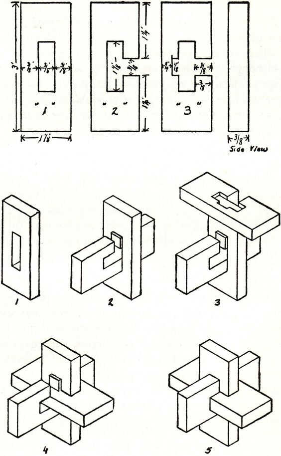
original sketch

Fusion's sketch
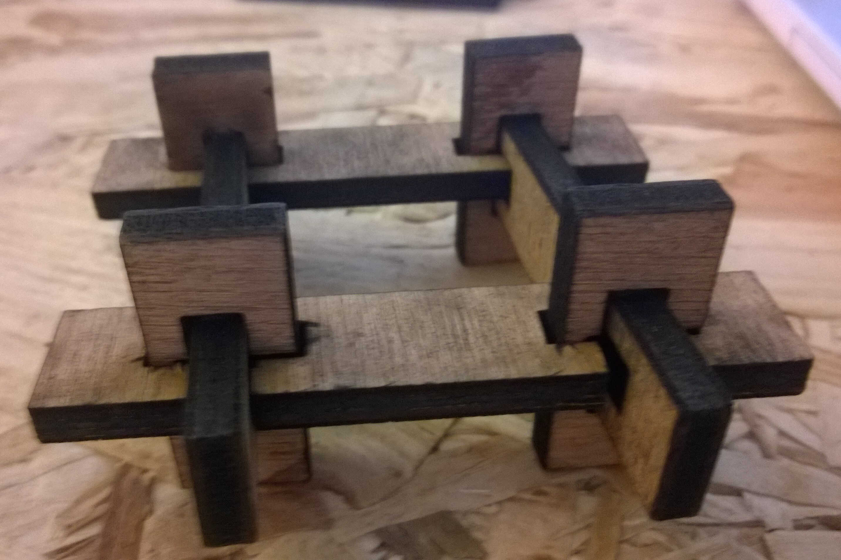
4 of such joints assembled
Source file to load here
Parametric
Later on I realized my file wasn't properly parametric. So I went back to it and added constraints in order for the shape to change proportionnaly to a small set of parameters. This wasn't easy, the more complex the shape the harder it was to find all the constraints to add. I think that the Rhinoceros/Grasshopper duo makes this task easier. I didn't find how to parametrize filets in Fusion. I should also have used the symetry constraints more. I would have gained time. My parameters are accessible directly on the sketch. I could also have used the parameters table but this table lists all the parameters which were used to build the sketch and they are not all relevant. This table is interesting because it allows paramters to be defined as function of others. This is also possible on the sketch when defining sketch dimensions, instead of entering a value by clicking on the dimensions you want to use.
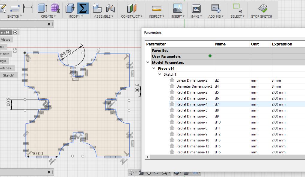
parameter table
Here a video of the use of the parameters:
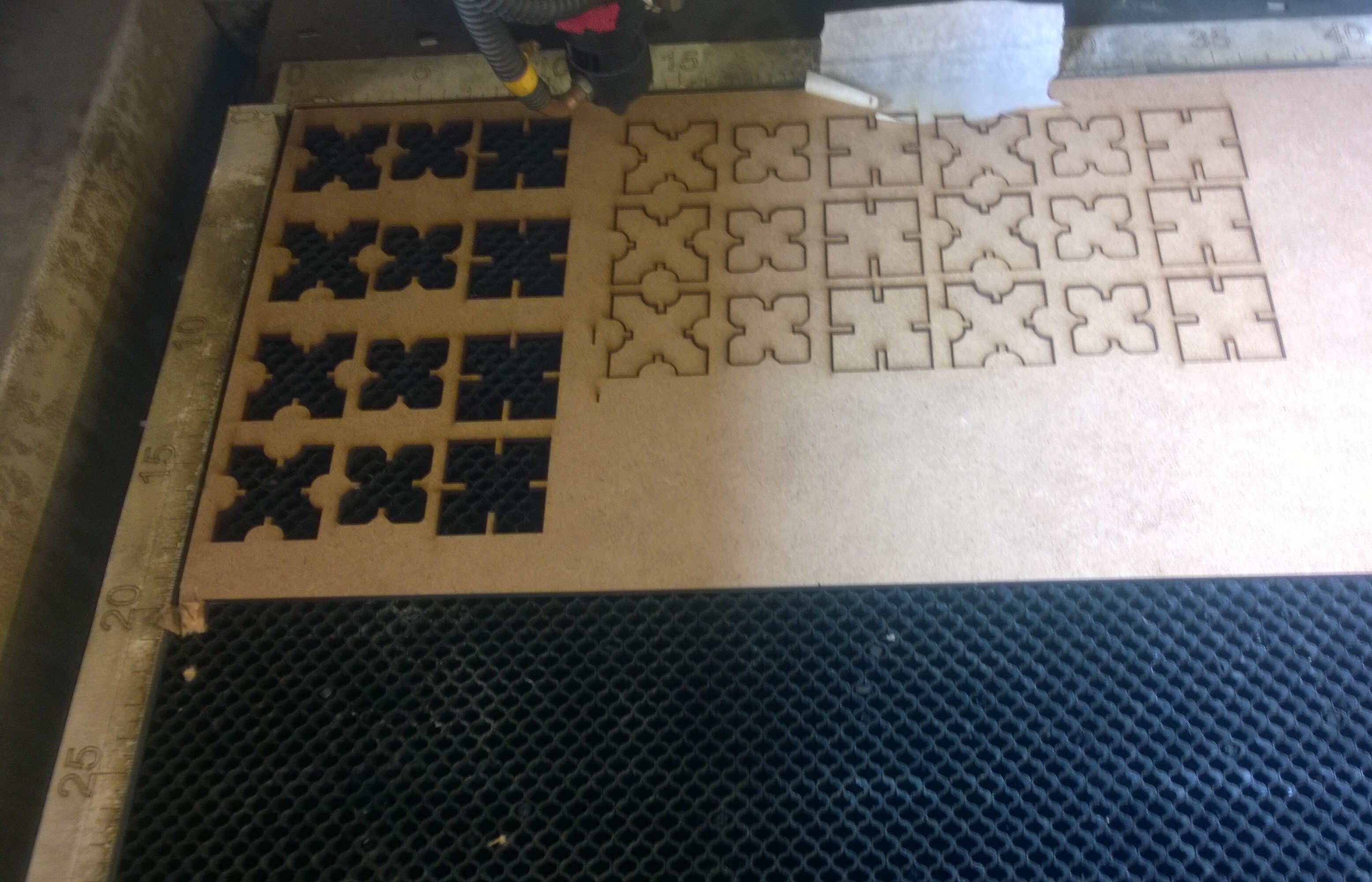
Laser cutting
I laser cut the 3 pieces with the slot width equal to the material thickness -3mm-. The pieces didn't fit properly as this technique doesn't take the kerf into account. I lasered again with slots being now 1 mm thinner than the material -2.9mm-. I lasered again with slots being now 1 mm thinner than the material -2.8 mm-.
width slot test
As seen in tests the kerf is around 0.15 mm for 3 mm medium (the cutting parameters being 60/55 in power and 1800 mm/s in speed). Hence I lasered a 2.8 mm slot width set of pieces.
width slot test
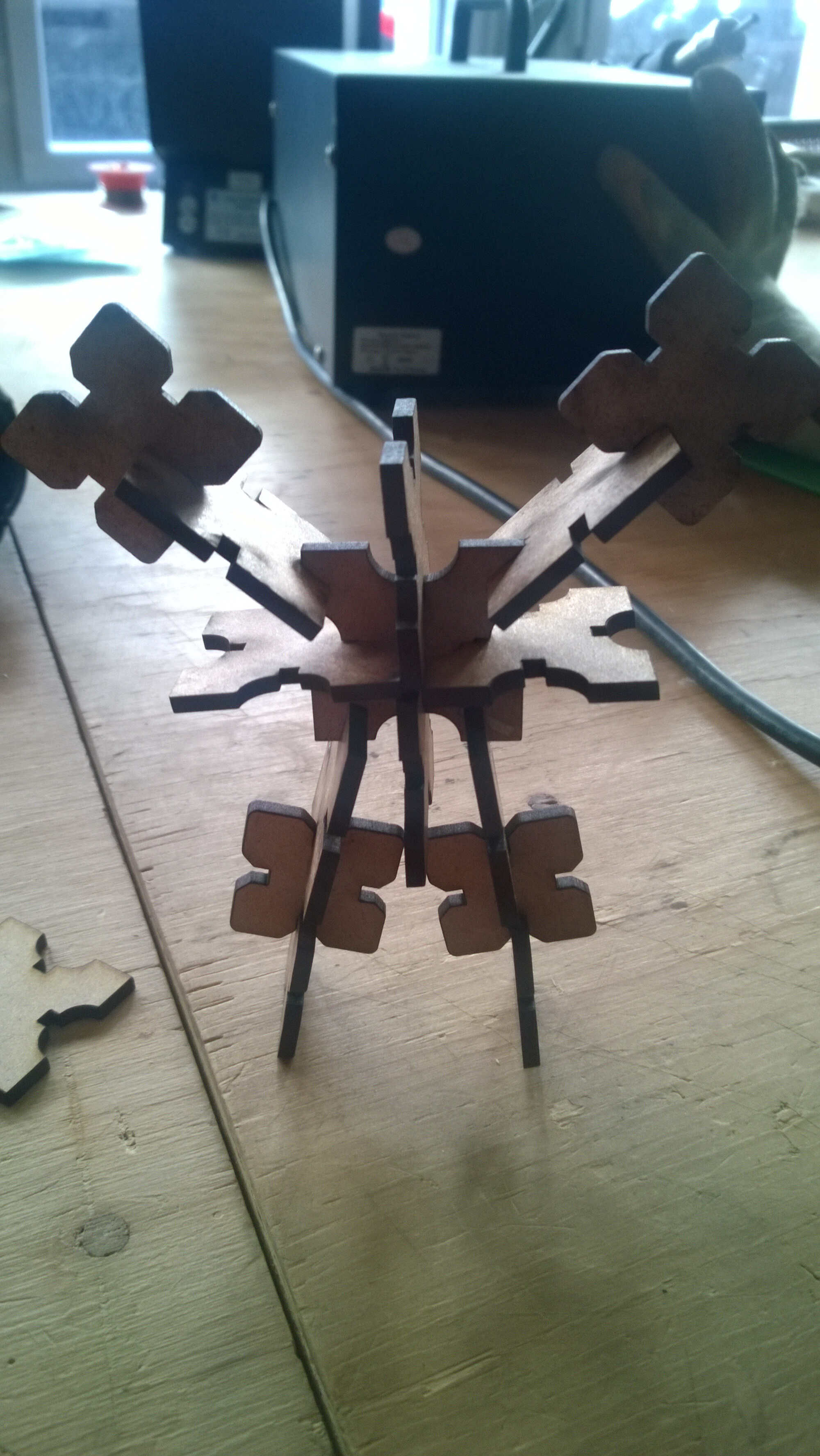
Here the fitting proof:
Source file to load here
So with this kit I am able to build "action" figure as shown with the test. It is also possible to build more useful construction such as a pot coaster.
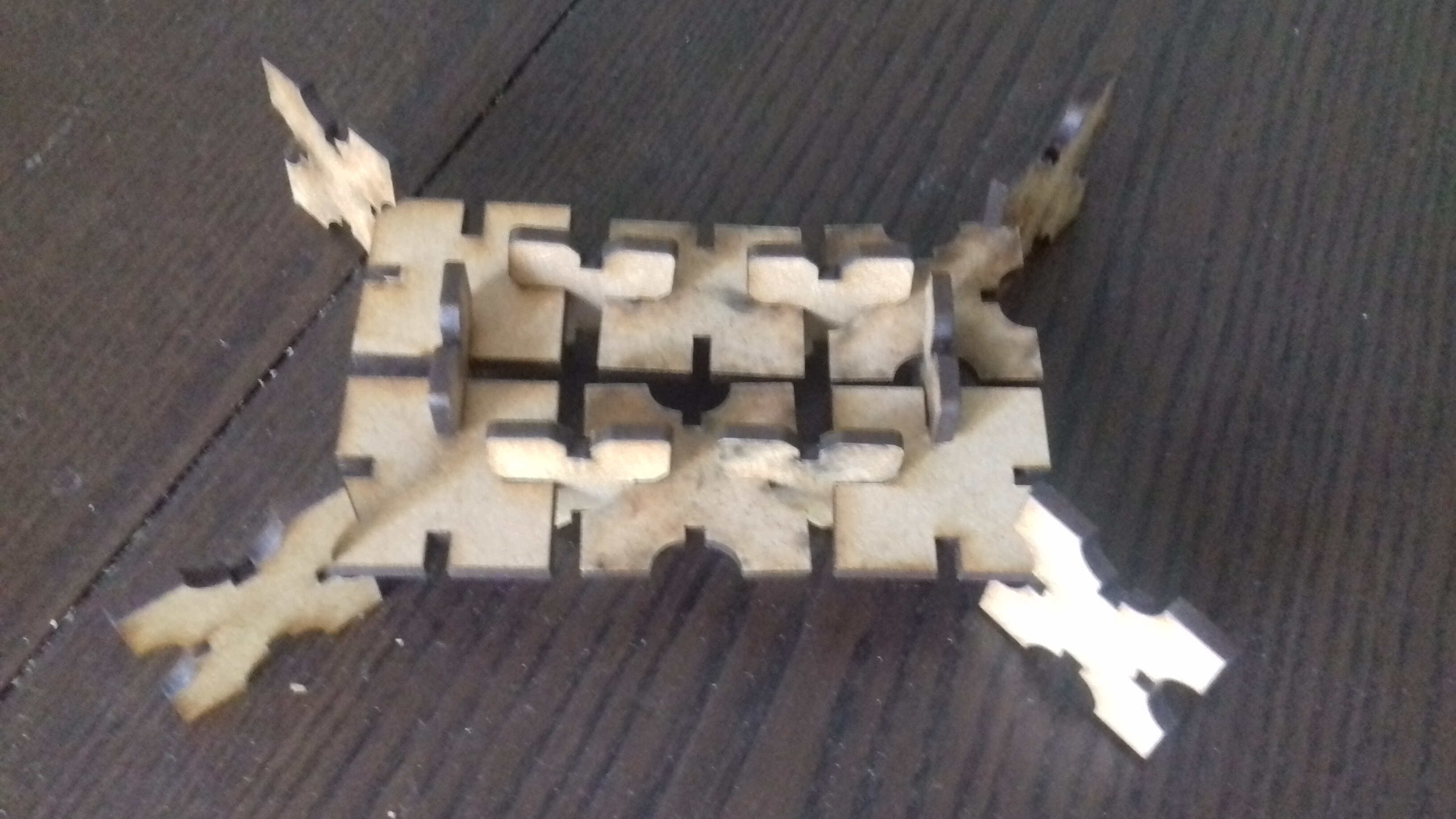
another combination
holding the pot
I retrieved a lot of information/correction/tips from the regional review. I will list them here. This section will also be used to indicate remarks I received.