Exercise 2: Computer-Aided Design
Assignment 2: Model a possible final project and post it on your class page.
3D CAD Design
What am I drawing?
I'm going to draw a piece of my first version of final project using a
FreeCad
When you launch FreeCad you can open an existing project or a new project. To start I have to set “Part” in the menu (Fig. 1). Remember that if you want to turn in the view you have to use “Shift” plus the right button of the mouse. Moreover, you can choose how to display your 3D object through “Drawing stiles”: you can find “Drawing stiles” in the toolbar or click on the right button of your mouse in the main window of the software. Finally you can choose the 3D object sight going to “Standard sights” in the toolbar or click the right button of your mouse. If your software stops, you can close and reopen it, but you remember to select “Part” in order to work in 3D.
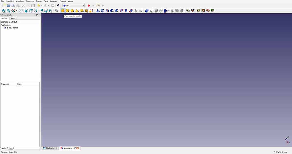
How to create a solid
To start I create a solid choosing “Cube” (Fig. 2) in the toolbar (the first of the yellow 3D solid).
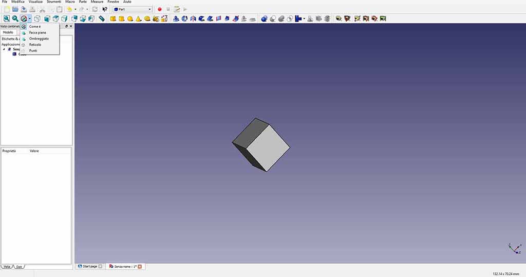
Then I click the cube in the window named “Labels & Attributes”: the cube becomes green and a window called “Properties and Values” opens (Fig. 3).
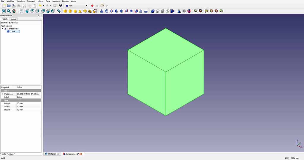
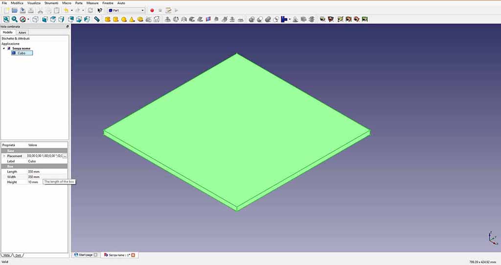
“Properties and Values” has two windows: in “Sight” I can set up how my 3D solid appears and in “Data” I can set up my data. So, I go in “Data” to set up solid’s measures: 35 x 35 x 0 mm (Fig. 4).
How to create the puzzle’s shapes
I can draw a new “Cube” or duplicate my main solid. I prefer the second option because it is more quickly so I click on my solid into the list with the right button and I type “Copy” and “Paste”. A second identical solid creates over the first. I set up for the new solid these measures (Fig. 5): 20 x 100 x 10 mm.
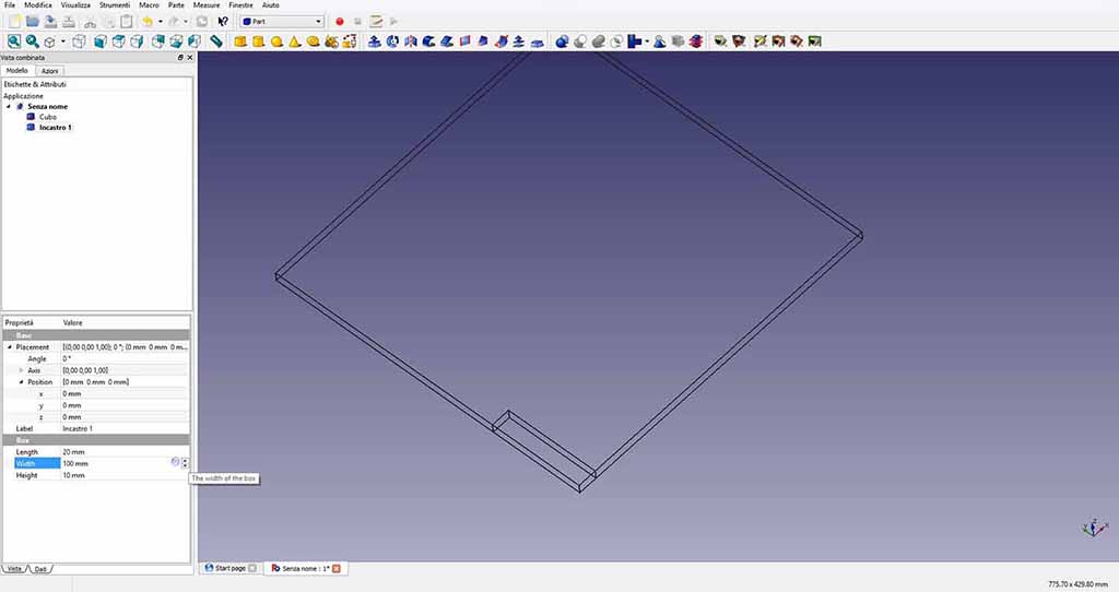
Once I have done it, I move it on the axes writing in “Data” (Fig. 6): Y = 50 mm.
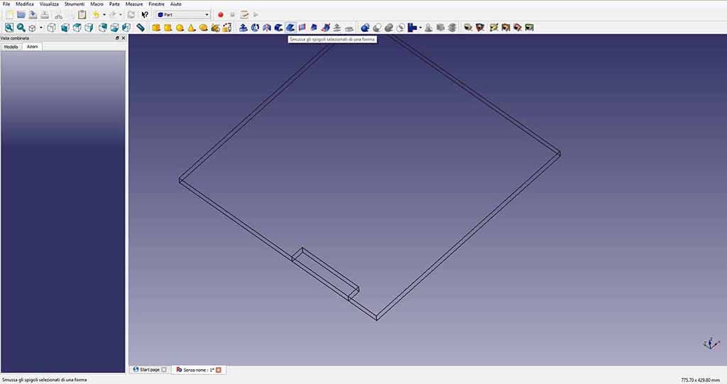
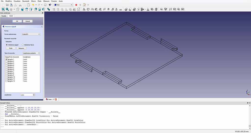
Now I have a quadrangular solid but I want a trapezoidal solid. To make this I can use the round action in the toolbar (in Italian “Smussa gli spigoli”). After I click “Round” a window opens in the left part of the display. I select my solid in the menu and the corners that I want to round (Fig. 7).
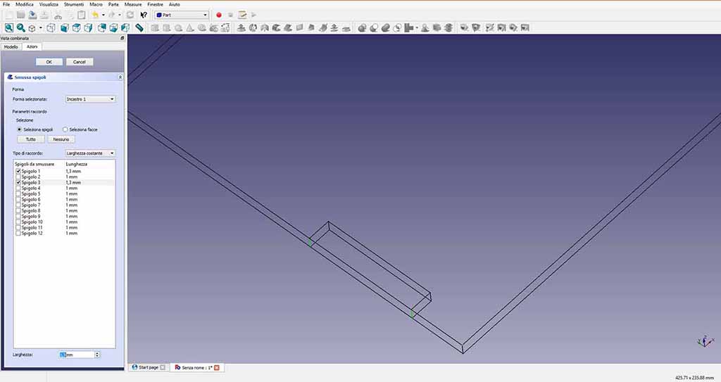
Then I set up 15 mm for the width and click on “Apply” (Fig. 8).
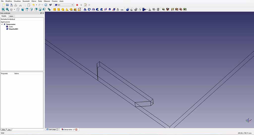
To smooth out the corners, I can use the “Smooth” function (in Italian “Raccorda gli spigoli”): I select my solid, I go to “Actions” and I choose Smooth, I select the corners to smooth and finally I set up 2 mm as radius. Now there are two ways to proceed: I can make this eight times (Fig. 9) or I can use the mirror (in Italian “Specchia una forma”).
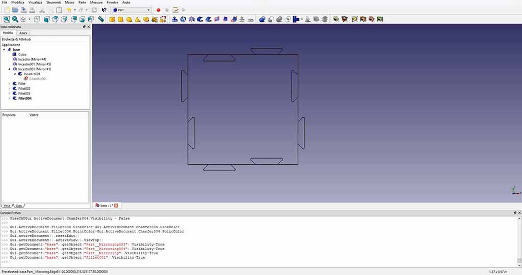
Before use the Mirror I have to copy and paste my solid. Then I have to select my copied solid (it becomes green), choose the Mirror action, select the yz axis and click on “ok”. A new mirrored solid appear and I can move it 150 mm on the y axis. I can use the Mirror again to create all puzzle’s shapes (Fig. 10) and I can select two solid to mirror every action.
How to use Boolean union
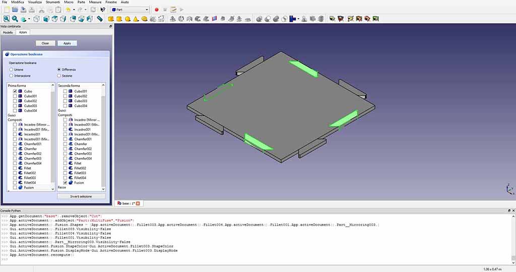
After I created my puzzle’s shapes, I want to remove those are inside the main solid. If I try to subtract one piece at once, the software creates a new solid named “Cut” plus a number every action. I can solve this making a union before. Therefore I have to select all solid that I want to put together and then I have to click on “Union” (in Italian “Esegue un unione”). At this point I can use the “Boolean union”: a window opens where I can indicate for the first solid that I want to keep and for the second my Union. Then I click on “Subtract” and “Apply” (Fig. 11).
How to complete my puzzle
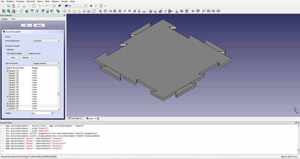
To round the remaining edges, I can use “Smooth” again (Fig. 12). Pay attention because now you have a lot of corners and it is boring to select every corners from a long list. I can solve this inconvenient clicking on the corner directly in the solid. A selected corner becomes green and I can select more corners at once. To select a hidden corner I can round my solid using shift plus the right mouse button.
Now two details remain: train tracks and 3D objects’ holes. To create the tracks where the train will go, I can make a solid (start from Cube) with size 350 x 5 x 3 mm. I have to move this Cube so that it lies approximately in the middle of the puzzle’s shape (x = 20 mm, y = 110 mm, z = 7 mm). The tracks are double (Fig. 13), therefore I have to copy and paste another and place it in the middle of the other puzzle’s shape (x = - 20 mm; y = 235 mm, z = 7 mm).
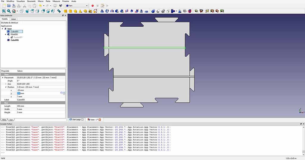
To cut the tracks from the main body I can repeat the operations done before with “Boolean union” and set “Subtract” (Fig. 14).
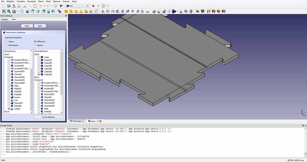
Now I can make the hole in which 3d objects are placed: a cylinder, a triangular prism and a prism with five sides (like a stylised house). To make the cylinder I can use the based solid setting a radius of 25 mm and a height of 5 mm. It is difficult to make a perfect triangular prism starting from a Cube, so I suggest to try with “Create parametric geometric primitives” with dimensions shown by the figure below.
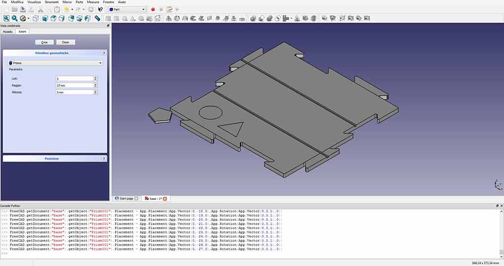
Whereas I suggest to start from a Cube to create the third prism because if you try to use “Create parametric geometric primitives” you can have a pentagon (Fig. 15). After create a Cube with side 50 mm it is possible to Smooth the two upper edges of 24.9 mm. It is important to set a value slightly lower than the actual size (25 mm) otherwise the program does not recognize it and crashes (Fig. 16).
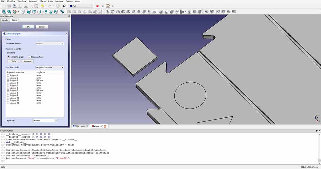
Now I can place the three solids in the right positions (Fig. 17): 75 x 60 x 7 mm for the cylinder; 175 x 51,5 x 7 mm for the triangular prism; 315 x 27 x 7 mm for the pentagonal prism.
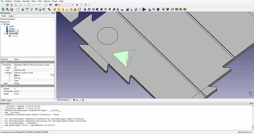
I can proceed as above subtracting the solids from the main body after joining them (Fig. 18).
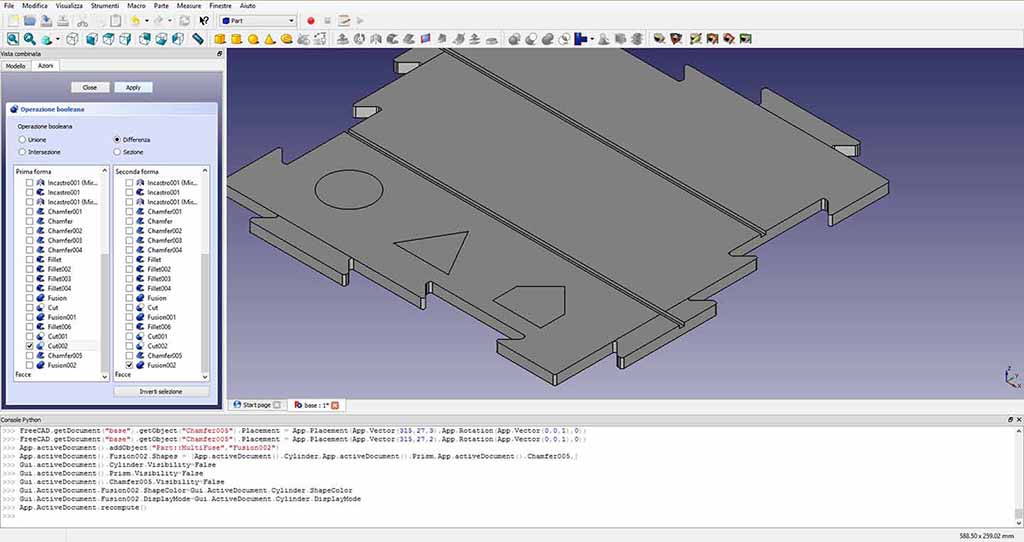
My 3D is completed (Fig. 19).
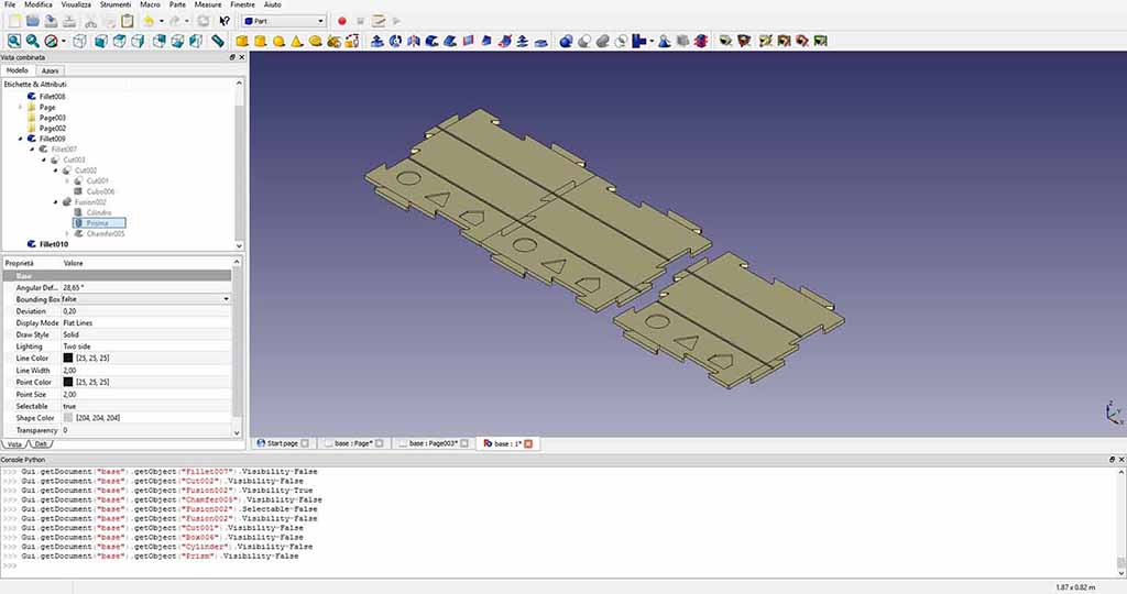
How to export 2D drawing
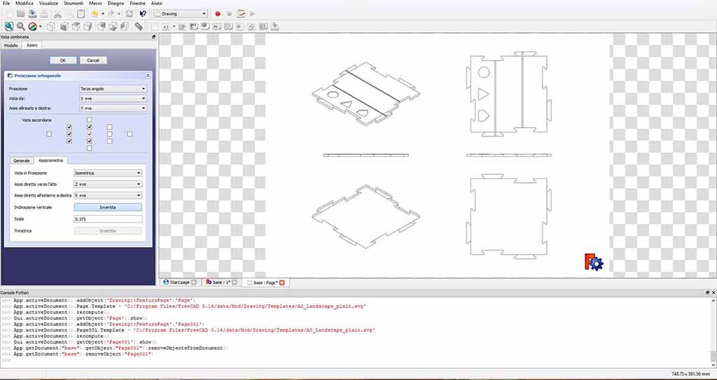
In Free Cad you can extrapolate the orthogonal projections quickly. First of all I have to choose “Drawing” function from the menu (instead of “Part”) and set up the sheet to use (Fig. 20).
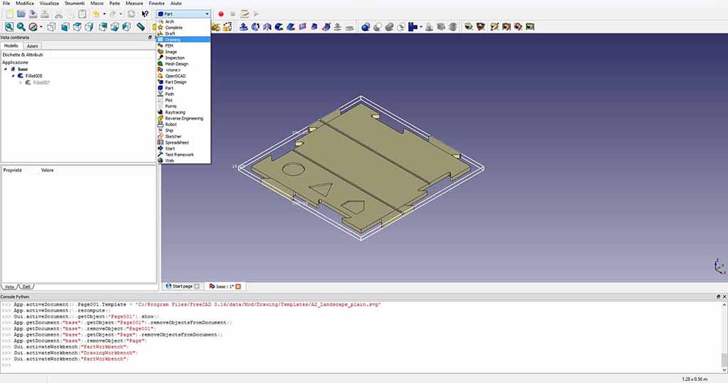
After selecting the solid to project, I can click on “Add a projection” and indicate the projections that I want to represent in the drawing. Finally I can export the pdf by the file menu (Fig. 21).
2D Vector Design
What am I drawing?
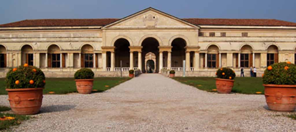
I decided to test Corel Draw for 2D Design. Corel Draw is a vector graphic editor useful to edit 2D images like logos and poster. It is the perfect choice for one of the logs of my new final project related to the city of Mantova, it monuments and its culturer. I designed the facade of Palazzo Te, one of the masterpiece of the city. I started from the photo shown below (Fig. 22) and I decided to simplify the facade to basic shapes and contours.
Corel Draw
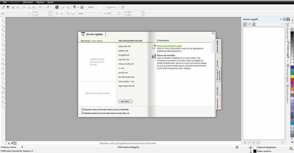
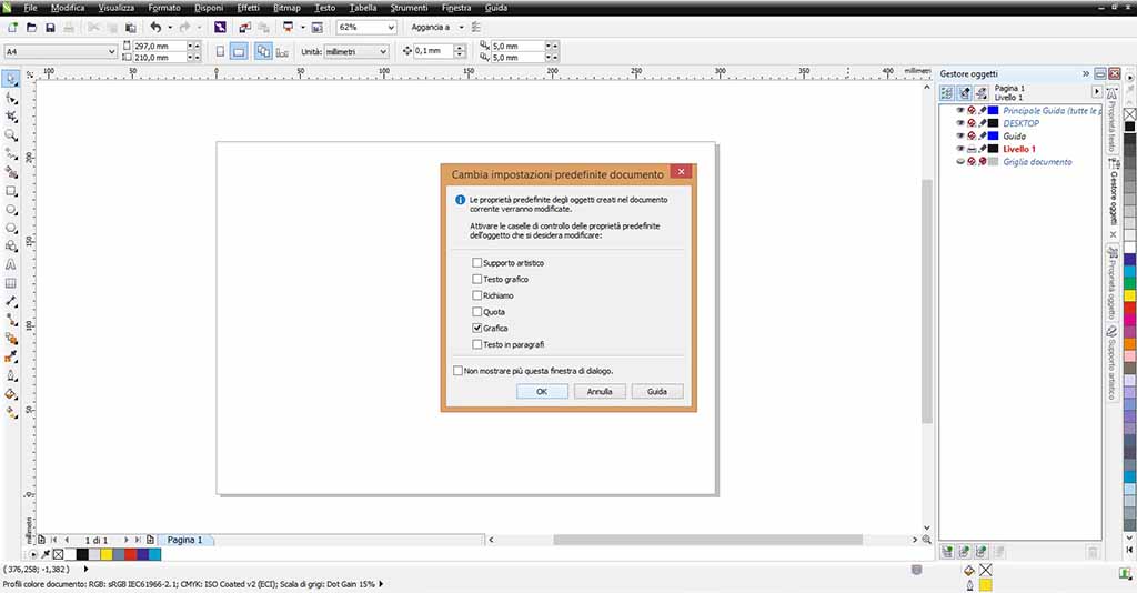
After I launched Corel Draw, I started a new project (Fig. 23). During each design phase, it is possibile to set and change the sheet dimensions from the toolbar. I chose A4 dimension (297 x 210 mm). My design is simple, so I used a only layer this time, but when I design more complicated drawing I create more layers. You can show and modify the layers in the right side pane.
How to create a shape
It is possible to create a shape drawing with a pen (free hand, bezier, etc.) or using simple geometric shapes (circle, rectangle, etc.). You can choose the command from the left toolbar. I used a rectangle shape to start (Fig. 23). Each shape can have a contour line and a filling. It is possible to set and change this parameter before and after you have create the shape. If you design a open line, this has only a contour line. When you design using the bezier, it is better to set a thickness the contour line. Otherwise you will not be able to view the path until you close the shape. I decided to set none thickness and a black filling before drawing. To set this parameters I clicked on the colours selector tool (Fig. 24).
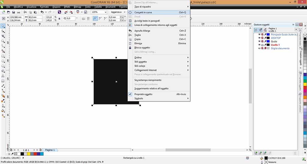
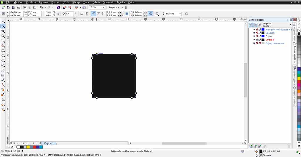
I designed a rectangular shape. To modify the single edges and corners, I trasformed the shape into a curve right clicking on the drawing and choosing "convert to curves" in the contextual menu (Fig. 25). Otherwise, the software consideres all the points together and ypu are not able to modify them individually (Fig. 26).
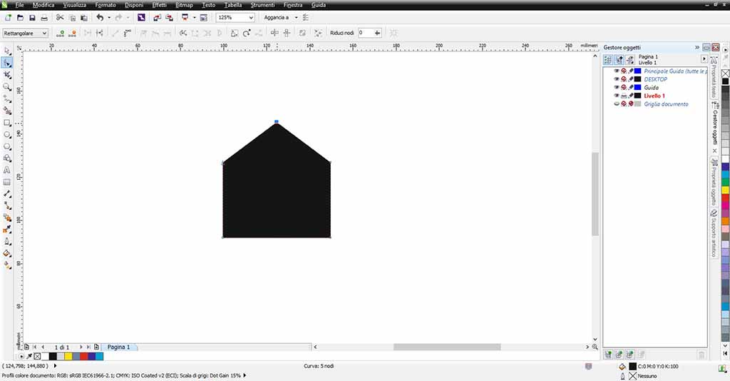
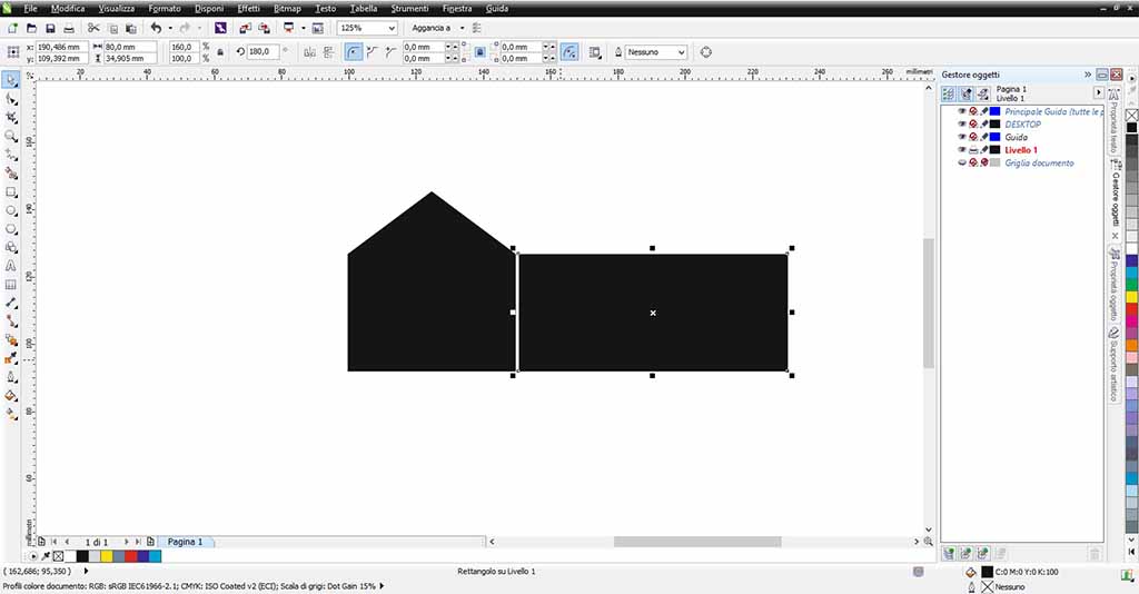
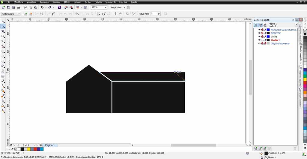
I edited the central point of the top edges to create the roof pulling it up (Fig. 27). After I created a new rectengle for one portico (Fig. 28).
To design the roof of the portico, I stretched the top corners of a rectangle (Fig. 29).
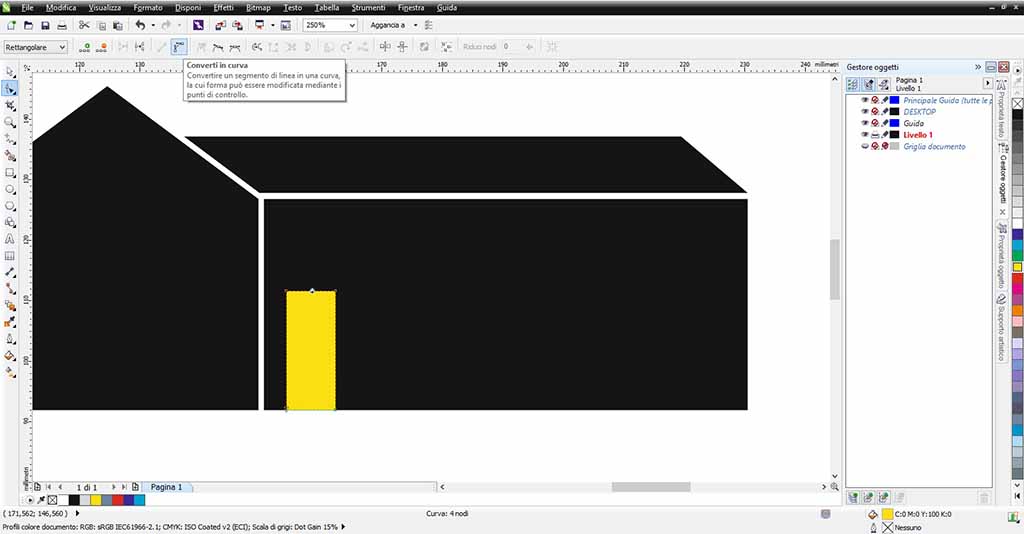
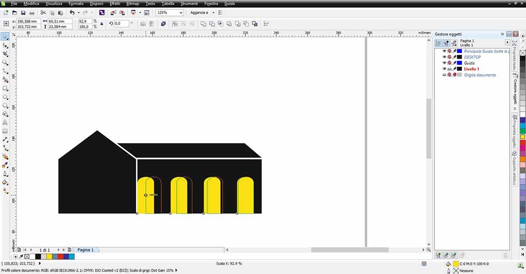
So I started drawing the arches. I drew the arches in yellow to see them better. As I did before, I strated with a rectangle, I converted it to curvers, I selected a point in the top line and I converted this line into curves using the toolbar command (Fig. 30). this way I was able to change every line into an arch moving with the mouse. I cloned four times the resulting shape, spacing them equally (Fig. 31).
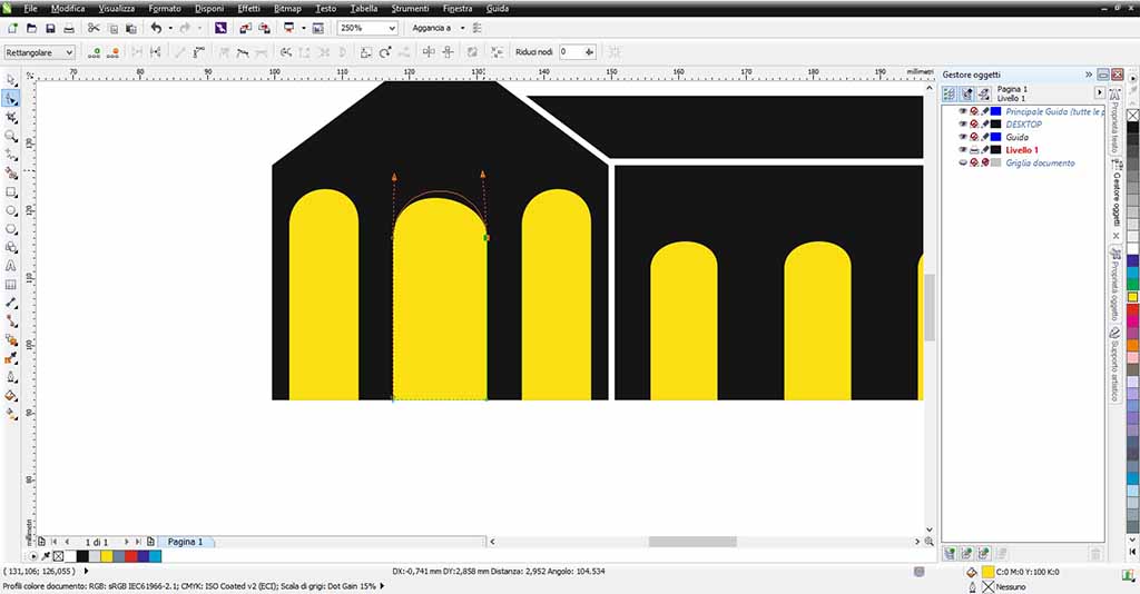
For the main entrance, I copied three arches and I modified them to reflect the actual sizes in the photo (Fig. 32).
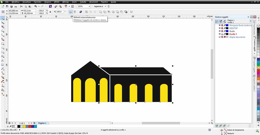
So I copied the portico (also the arches) and I mirrored it using the horizontal mirror tool in the toolbar (Fig. 33).
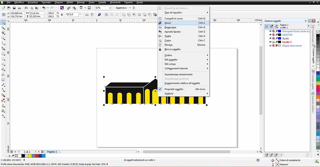
Finally I joined all the shapes clicking on the drawing and choosing "union" in the contextual menu (Fig. 34). Now the facade is finished (Fig. 35).
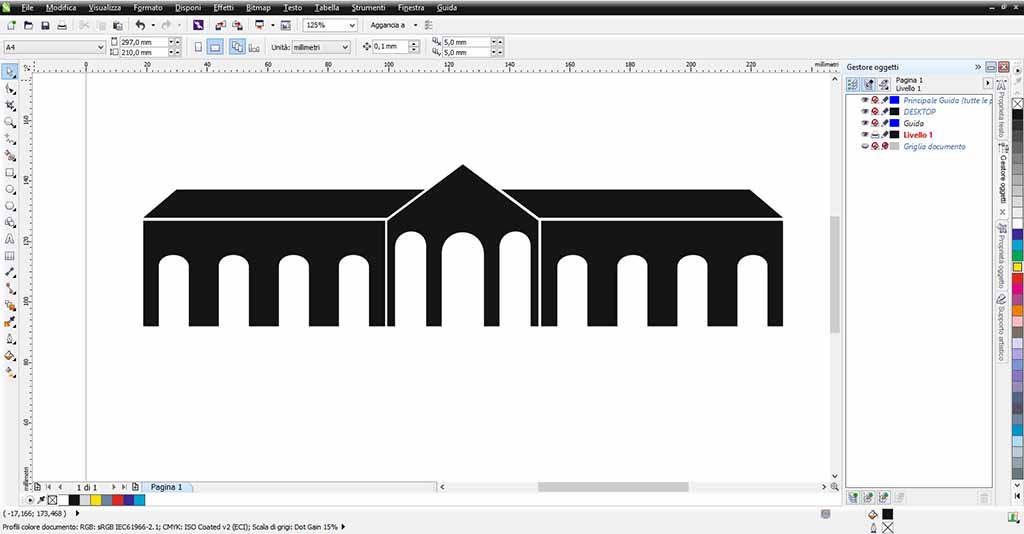
As you can see on my final project I vinyl cut it and other logos I designed later.