
04. Electronics Production
Building my first PCB
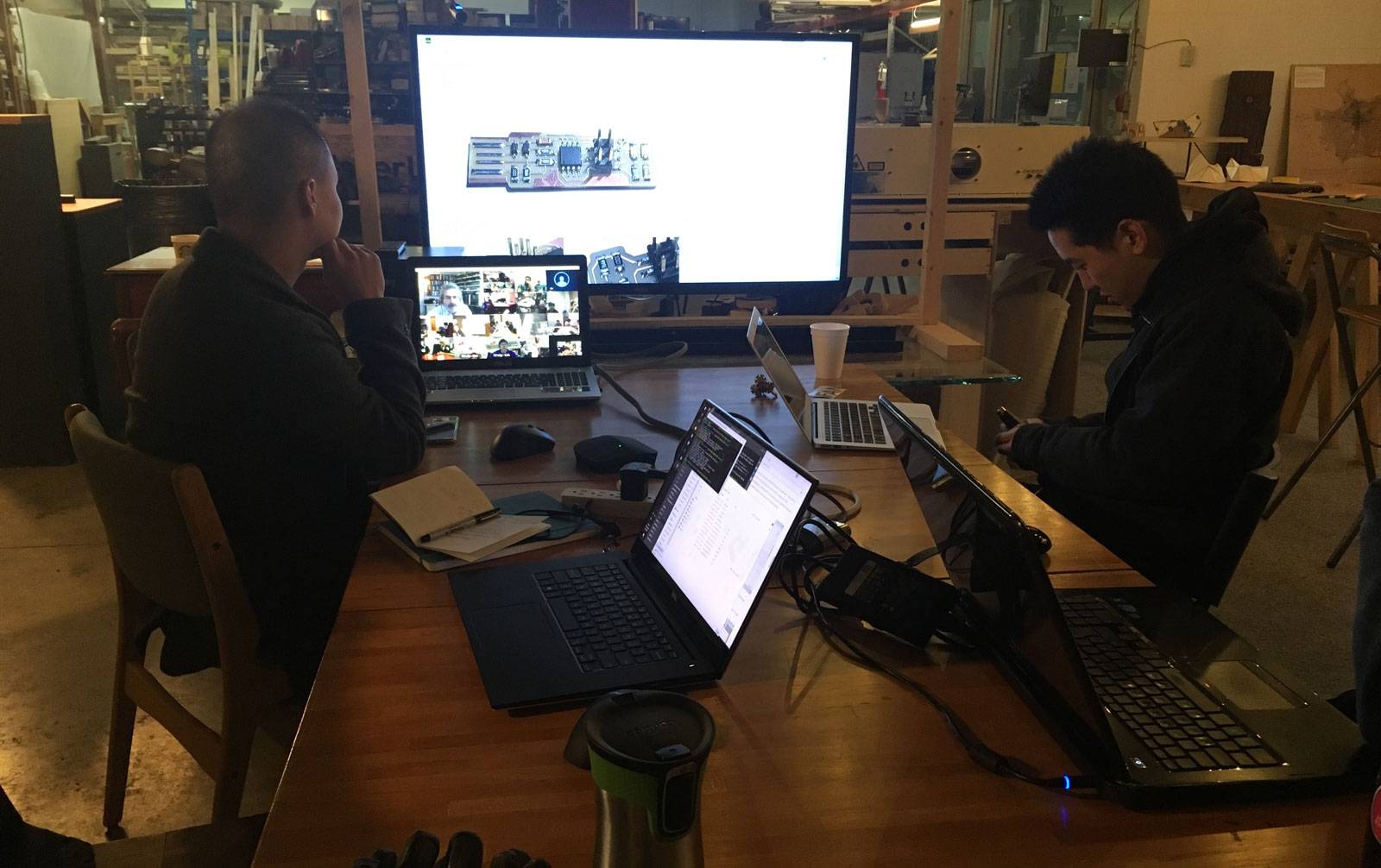
This week we covered the common methods for PCB production (etching and milling). We also discussed the advantages and disadvantages of through-hole vs. SMD parts. We finished off by covering some student designs for ISP programmers as a starting point for procusing our first PCB.
Learning Objectives
- Describe the process of milling, stuffing, de-bugging and programming
- Demonstrate correct workflows and identify areas for improvement if required
- Make an in-circuit programmer by milling the PCB
Assignment
PCB Milling
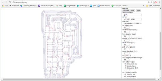
We started by using Valentin's design, generating toolpaths in the web based fab modules. Offset is important here, as it clears copper around your traces that can cause shorts if your solder sticks to them. Toolpaths with high offset values can take some time to load.
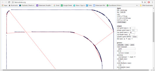
Then repeated the process for the cutout. This requires a separate toolpath because it uses a larger bit (1/32"), and cuts through the material. Currently Fabmodules does not have automatic settings for Shopbot PCB milling, so we used the plywood workflow and adjusted the settings close to the ones for the roland machine. We initially had issues with this design's traces coming out too thin, so Derek edited the design to compensate.
The edited png source files and my resulting sbp files are available here.
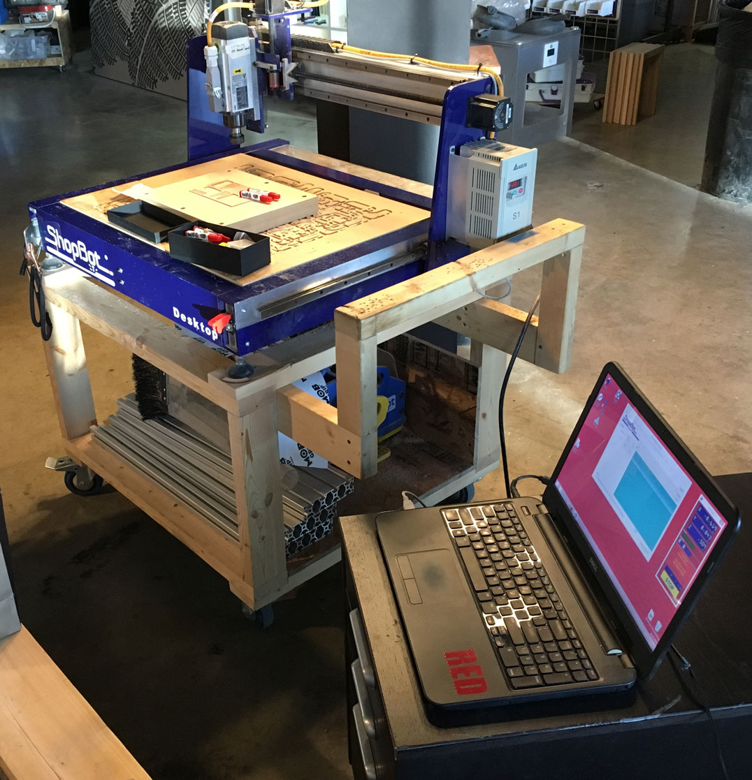
Our lab is using a ShopBot desktop for this process. It has a z-zero plate, but due to the fragile nature of the 1/64" bit, we manually zeroed the z axis.
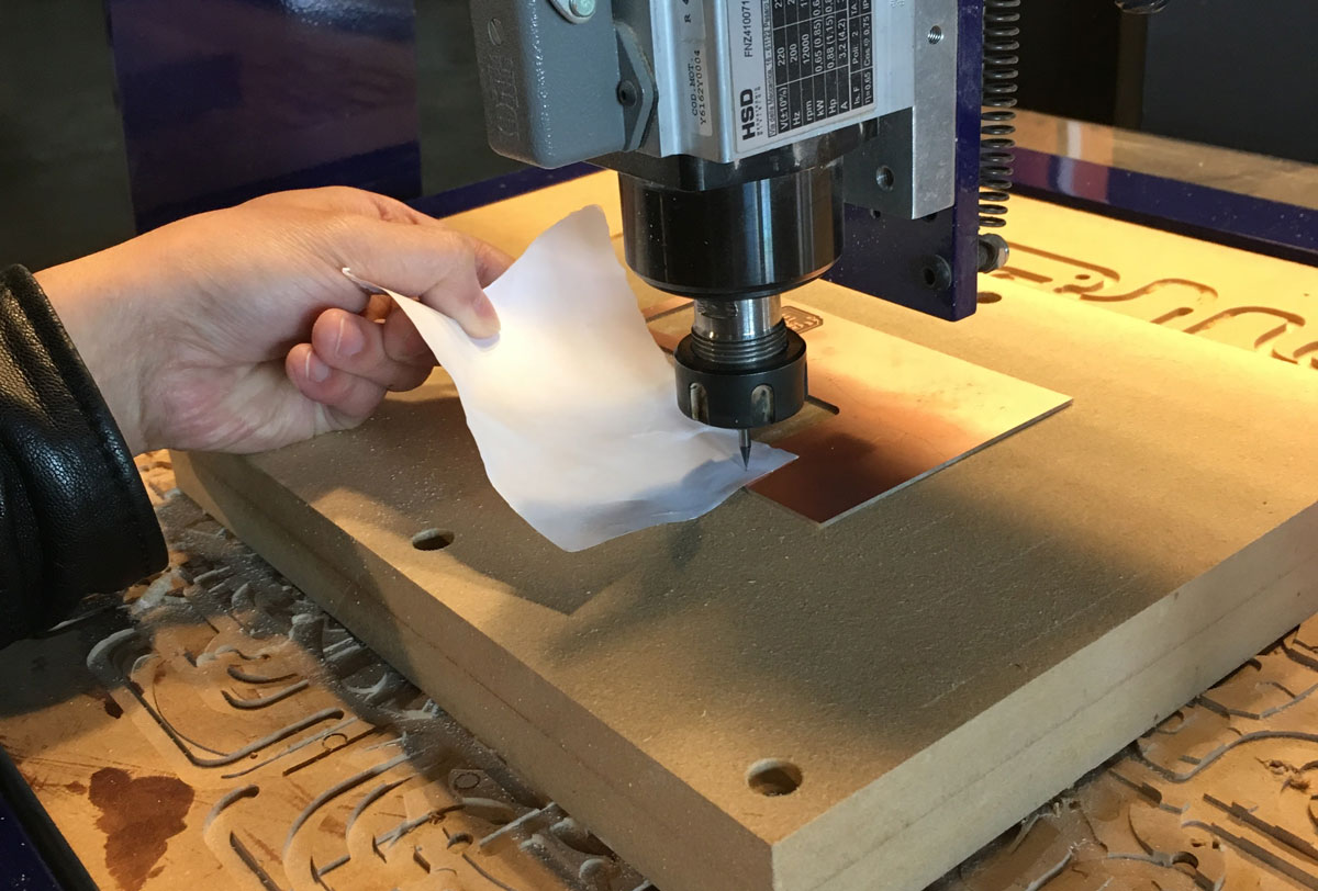
We used paper between the bit and copper, slowly adjusting Z height until the paper couldn't slide back and forth.
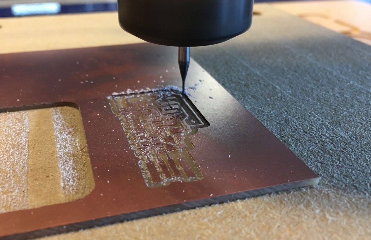
With the CNC set up, it's time to get milling! The process took about 30 mins for the traces and the cutout.
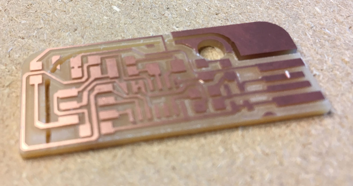
My copper board. Even with 7 offset paths, some small bits of copper were left between traces, so we removed those with a knife.
SMD Soldering
Though I initially milled Valentin's design, I started practicing my soldering on an extra board based on Brian's design. It went better than expected, so I chose to finish the process using this board design.
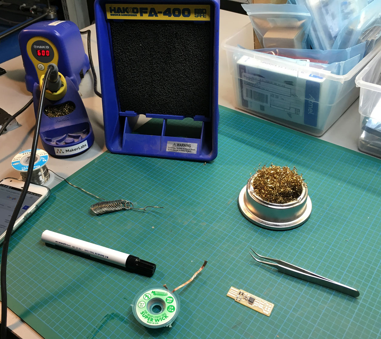
My soldering setup: Flux Pen, braid, tweezers and an exhaust fan at the ready. If you're used to through-hole soldering, SMD soldering is strange at first, but it starts to feel natural very quick. Flux really helps keep the solder where you want it to go. I had a couple issues with too much solder, but they were easily solved with a bit of braid or the solder sucker.
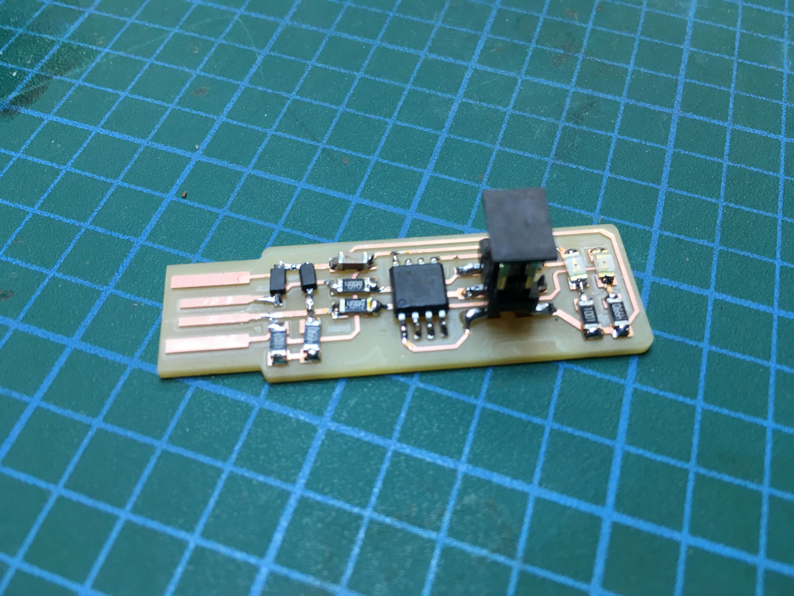
This is how my board came out. Not bad for a first timer :)
Programming
This is where things can get tricky. I recently switched to a Windows PC, and most of the documentation for these ISP boards have complex installs for windows. I also heard AVRDude can wreak havoc on systems, and potentially corrupt registries, so my plan was to avoid that if possible.
I managed to simplify the process a bit, starting with Brian's instructions. This is the process that worked for me using an Atmel Studio and an Atmel Ice programmer on Windows 10.
Start by installing Atmel Studio. This includes a lot of dependencies and an environment for programming your board directly through GUI. You'll also need a copy of the firmware source. Unzip that somewhere you can find it easily.
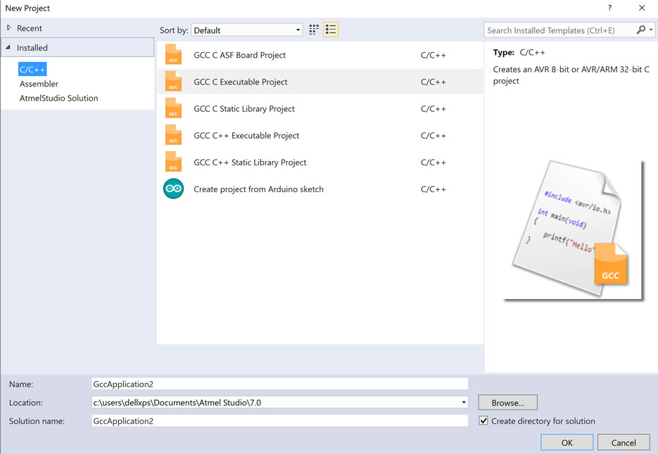
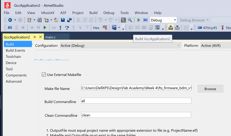
Open Atmel Studio and start a new GCC application project.
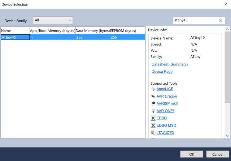
Choose ATTiny45 in the device selection dialog.
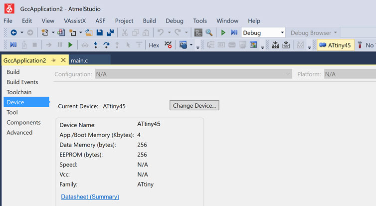
Click the ATtiny icon in the top bar to bring up the GCC Application window. The build tab to the left is where you can select an external makefile (in the firmware zip we downloaded).
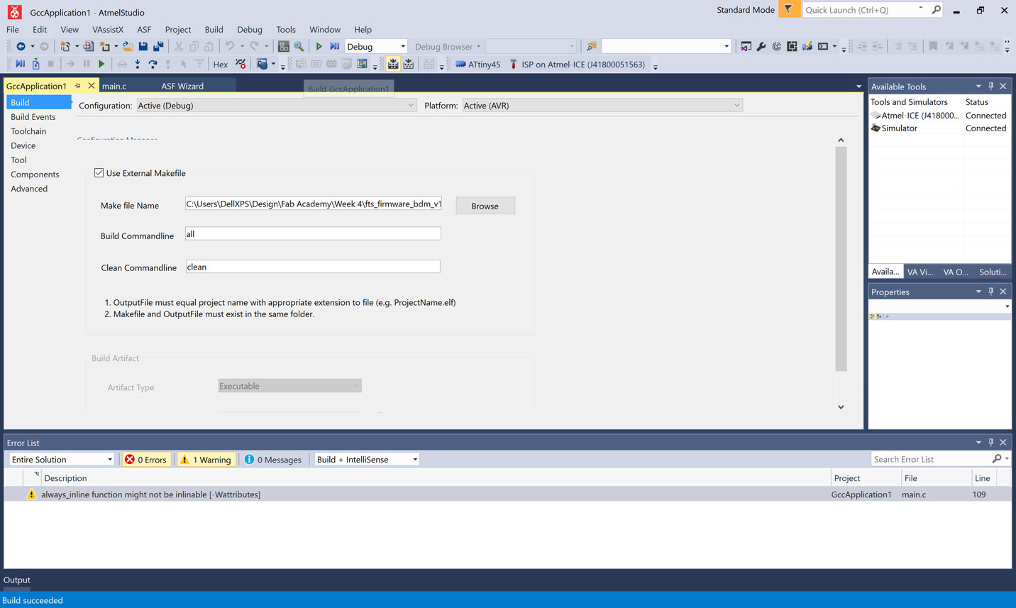
This is where you can build a firmware hex file. Pictured above, it will throw an error unless you manually change the programmer listed in the makefile.
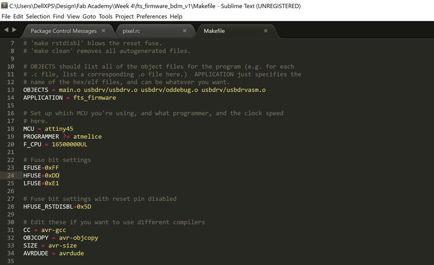
We used an Atmel Ice Debugger/ISP, so I changed the PROGRAMMER ?= line to atmelice. This will vary depending which programmer you intend to use to get firmware onto your board.
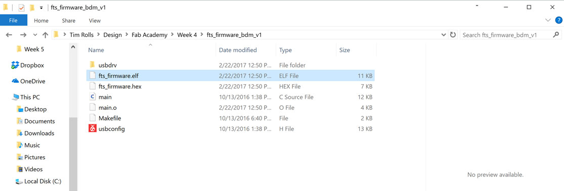
Back in Atmel studio, use this icon to build hex/elf files once you have manually added your programmer type to the makefile. Those files should appear in the same folder as the makefile.
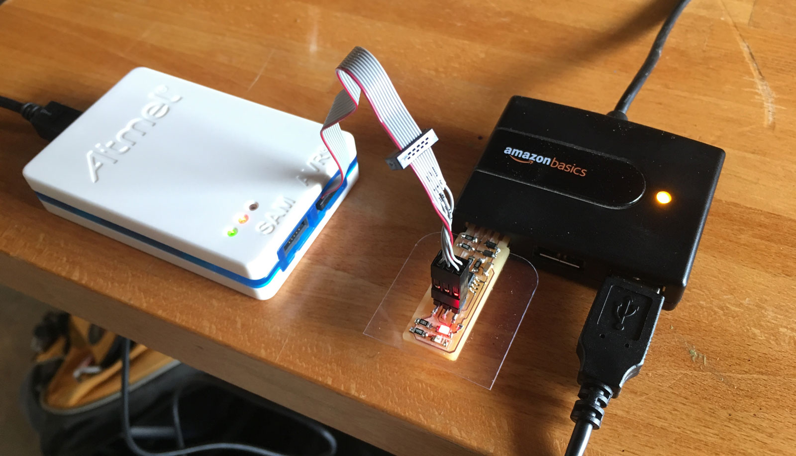
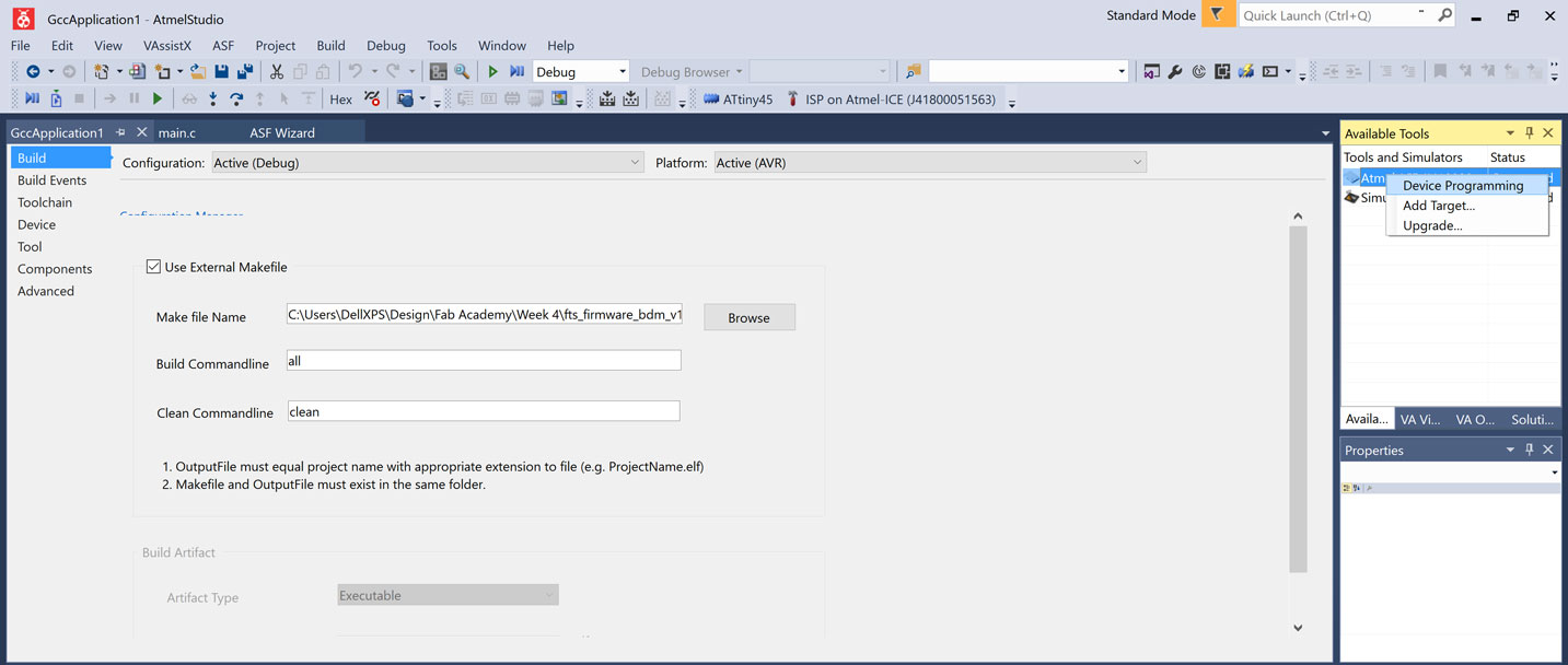
With those files made, connect your programmer to your computer, and the cable to the board you built. Double check that pin 0 on your board matches the pinout on your programmer. Here I used a USB hub, but it's not necessary if you have enough free ports. Your programmer should appear on the right under "Available Tools". Right click it and choose Device Programming. This brings up a new window that allows us to program the firmware we just made onto our board.
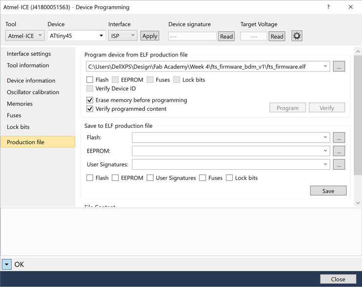
Under Production file, choose the .elf file we just built. This is the firmware that turns your board into a functioning programmer.
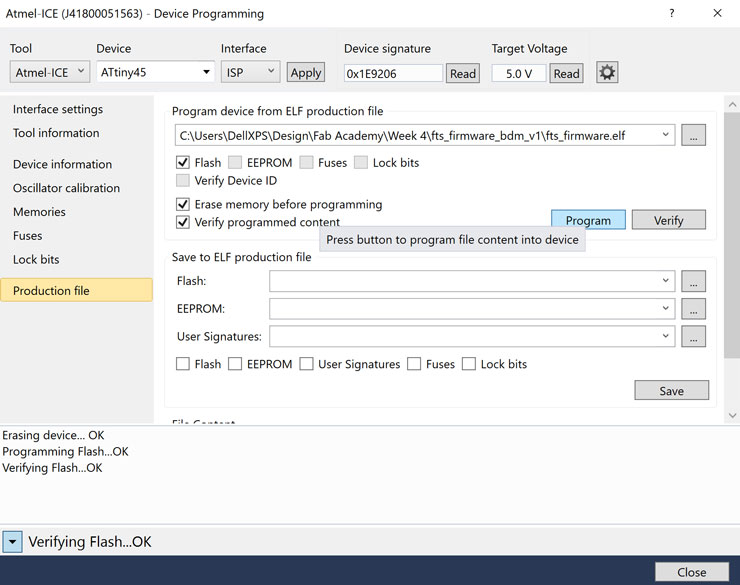
Tick the "Flash" box, and the Program button will appear. verification is on by default, and I recommend leaving it on to have the software automatically verify that the firmware on the device matches the file on your computer.
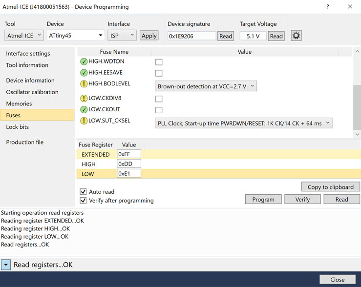
Next we need to set the fuses. Under fuse registers we want 0xFF / 0xDD / 0xE1 (also indicated in the makefile). Hit Program once you've set those values.
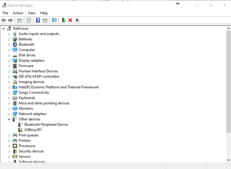
At this point we want to verify if it's being recognized in Device Manager (requires a reconnection to USB). In my case, it showed up, but without drivers. The easiest way to install them is by running Zadig and selecting the libusb drivers
From Brian's instructions:
The USBtiny programmers use a generic libusb driver, but Windows 10's driver signing policy makes the installation more complicated. Fortunately, there's a tool that helps with this. Download Zadig and launch it. Plug in your programmer, and select the "USBtinySPI" device in the list. (If it doesn't show up, go to the Options menu and click "List All Devices". The driver you want to install (to the right of the green arrow) is either libusb-win32 or libusb0. Click the "Install Driver" button.
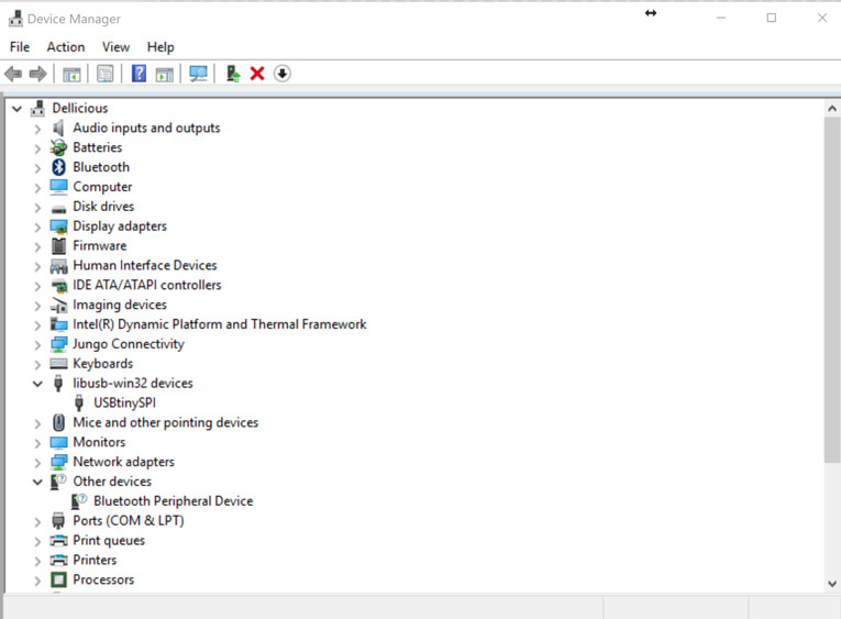
Once we verify that it's recognized as a USB device, it's time to blow the rstdisbl fuse. This will permanently disable the ability to program the board, so make sure it's working before moving on.
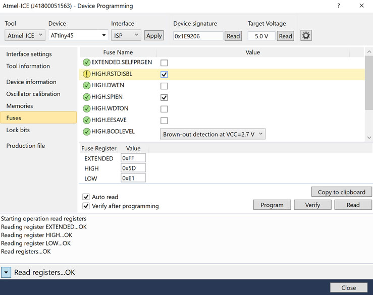
Check the box next to the rstdisbl fuse, and hit program. The last step is to disconnect VCC from the Vprog pin on the ISP header by removing the bridge on the solder jumper. That's it!, you should now have a fully functioning ISP programmer.
Testing
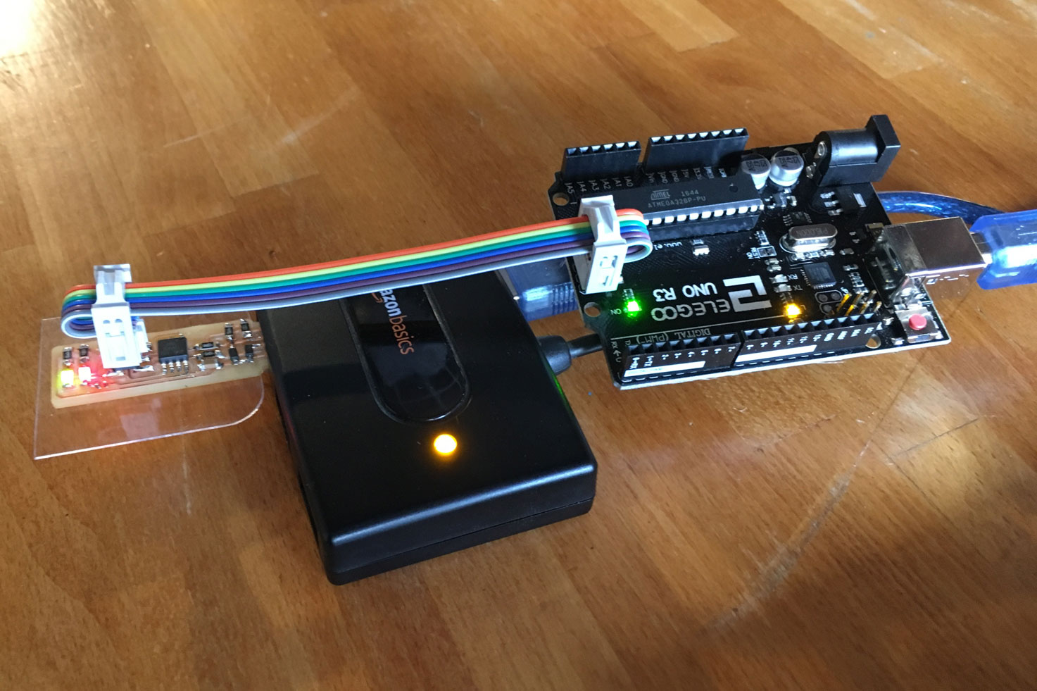
I tested my progammer on an arduino board, because they're relatively easy to recover if something goes wrong. To start, make sure they're both connected to USB and connect the ISP header to the ISP pins on the arduino board. Double check that the orientation is correct (make sure pin0 on your board is conneted with pin 0 on the arduino).
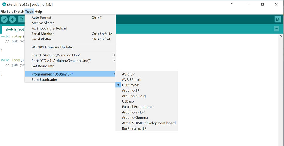
In the Arduino IDE, select your board from the list of programmers, then select "burn bootloader". This will use your programmer to overwrite the arduino's bootloader. Once that's done, you can verify that the arduino works by uploading a simple sketch to it, like the included "Blink" example. After uploading, the arduino's onboard LED should blink, indicating that everything is working.