Programming
In this i make the rgb board programming with my fabisp
first i download the code from the fab academy website this is neils code I modified that code then i make the changes in that chnage the pin whatever i take i edit that pin here
The code is basically defining the pins of the microcontroller and making them glow as per a fixed pattern
In neil's code of RGB i make very slight change of delay other thing are same I upload as it is programme to my board.
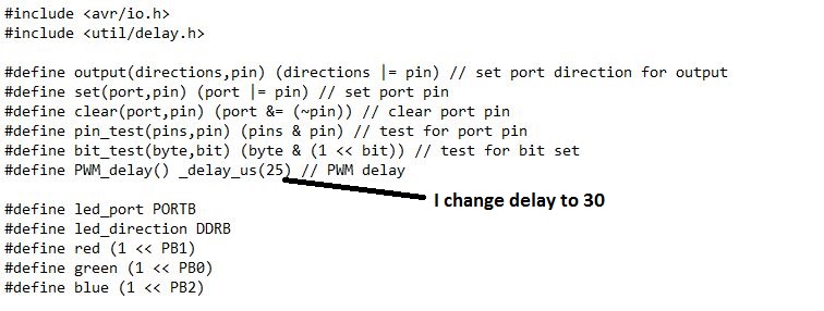
In this code I devide whole code in 2 part to understand the code ,In first section of code first we include the library which We have required and then how much things we required that also defined i.e define the pwm ,In this I change the pwm delay as 30.
Then define the PortB as output port In that we use the 3 pins like
PB1-RED,
PB0-GREEN,
PB2-BLUE
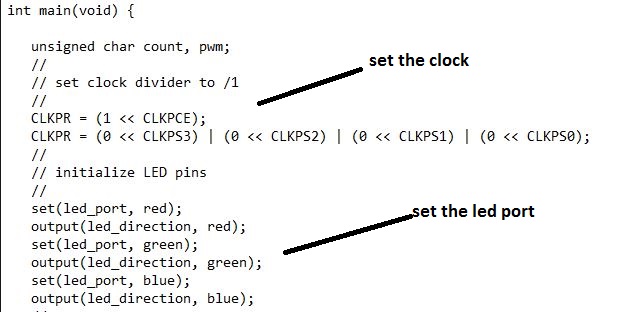
Then set the clock divider and then set the all led pins such as RED,GREEN,BLUE etc.In this part there is one more declaration i.e unsigned char count this is used for counting how much time it count the led blinking
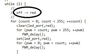
now the actual programming logic start ,in this used the while loop this is the main loop of code in that loop there is one more loop i.e for loop in that for loop two values are set for pwm count and normal count also.In this main target is off--->red led for that first clear the led port clear then slowly red led goes to on state because of PWM and then set the red led port.now the red led blink. RED led slowly change from off state to on state and turns on
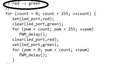
The target is red ---> green in this part ,for that first clear the red led port and then set the green led port then then it slowly change the state to the green light
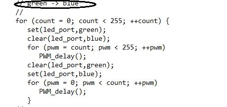
The target is green ---> bluein this part ,for that first clear the green led port and then set the blue led port then rgb led it slowly change the state to the green to blue light
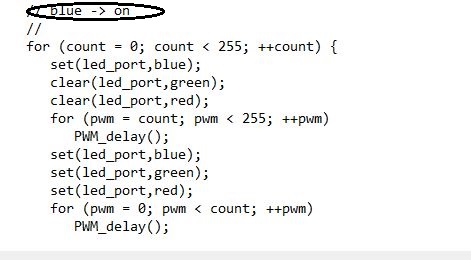
The target is blue --->onin this part ,for that first clear the green,red led port and then set the blue,red green led port then rgb led it slowly change the state from red to green then to the blue
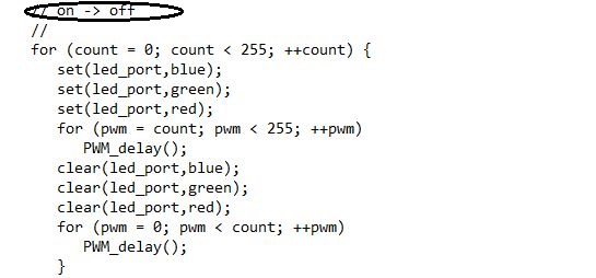
Its time to off the led the target is on---> off the rgb led,for that clear all the blue red and green port then led goes in the off state.
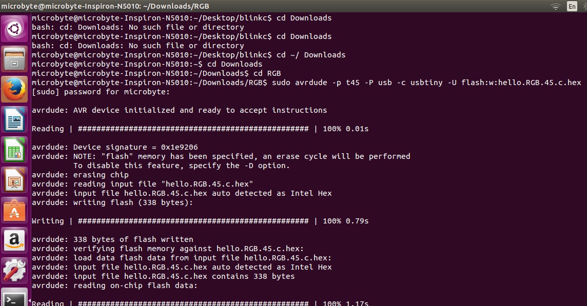
this is the code for rgb led and I run this code on my rgb board through fabisp.I connectthe all programming pins of RGB board to the FABISP board

//sudo make -f hello RGB.45 make. This will create the make file .
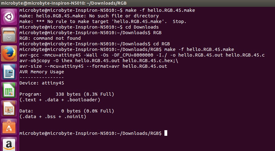
//sudo make -f hello RGB.45 make.c.programme.usbtinywe target this make file.make changes in this file
Result of my rgb board
Relay board -Used in project
This is my relay board in that I use the Attiny45 and the solar panels output connect to the relay.And relay used for motor turn on and offaccording the signal.

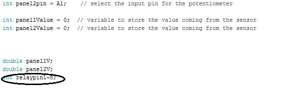
This is the code to run the motor through relay.the logic is when I get the signl from solar panel then relay on or off and this will be start the motor.In the starting part of the code I initialize the panelpin at analog input i.e A0 and A1 then I initialize the relaypin to the digital out pin 8.
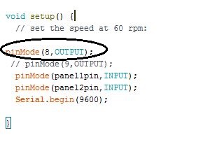
Then I set the pinmode as output for pin no.8.It means the output is work at pin no.8 and according with input signal this pin high or low
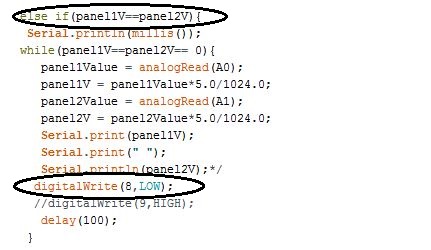
Then the logic of code is ,If the panel1-panel2 result is not eqval to zero then the pin 8 is high and relay on motor on

TIf panel 1-panel2 its result is equal to zero then pin 8 is low and relay off and and motor also off.
This is the code or logic of my board.you can see the working of my board on my project video
Conclusion
In this I learn more output device and i finish some part of my final project.In rgb code i learn that how the led change its state from one color to other