Before starting this assignments we had short listed three machines to make and ultmately we had to choose one amongst them.
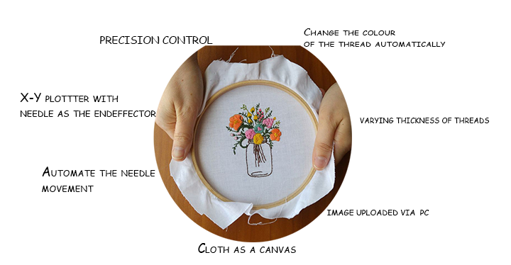
Automated embroidery machine
Embroidery is a special sewing art done in India, it uses needle and special threads to make intricate and delicate designs, its a very painstalking task and requires expert hands.
Thus we were thinking of automating it
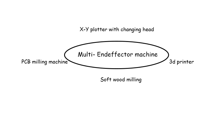
Multiple end effector
This is a very ambitious machine, its a 3d printer a laser cutter a PCB milling machine and a laser cutter combined in one.
It will be an X-Y plotter with an arrangement to change the end-effector.
WallBot
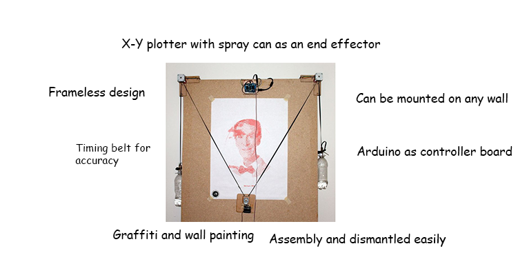
WallBot is painitng machine which clings to the wall and paints it, graffiti can also be done with it.
Although change of colour during the working of the machine is a bit tricky at this moment it can be done in further revisions.
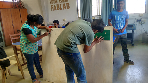
The Team

The Machine
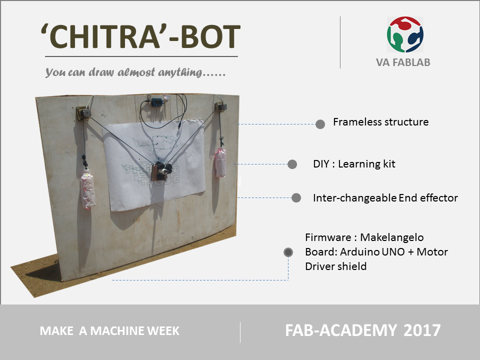
We did not want our machine to be limited by the size of the frame, thus we decicded on a frameless machine which can mount on any wall
After a lot sessions of arguements and brainstormings we finally arrived at a decision
We are going to make a Chitra-Bot
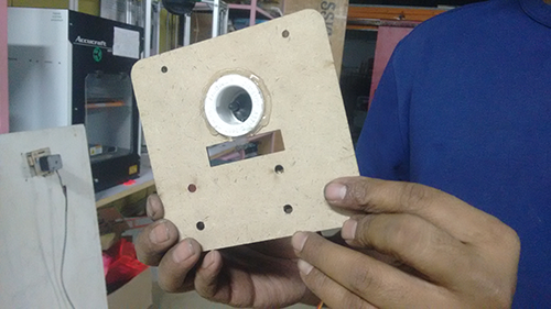
The machine will paint the wall or draw a graffiti with a spray can, for simplicity we will try the machine with a pen as an end effector we dont want to waste expensive spray cans in trials
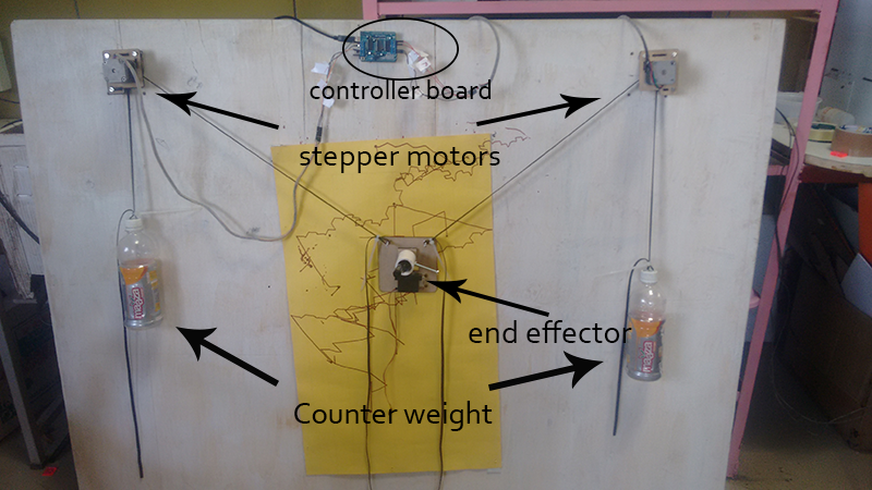
We will use arduino Mega 2560 as our controller board (we ultimately shifted to arduino uno)
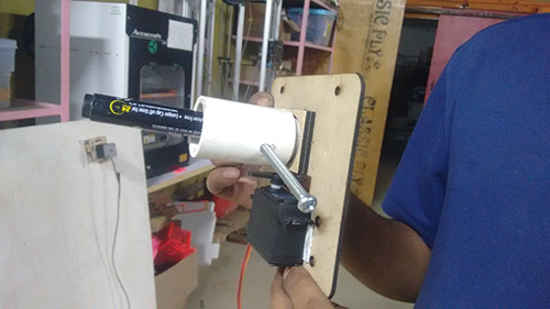
We are using two stepper motors to move the machine and a servo motor for the end-effector
For precision we are using timing belts and gears on the shaft of the motors
The machine will keep on improving and thus will have several revisions, for our first revision we will stick to a 8*4 ft size plywood as a canvas
There are a few machines designed on a similar lines and we are going to experement with there firmware and GUI
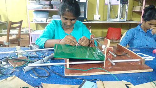
Arundhati work on following point -She mill the fabnet for our machine.
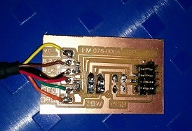
this is the fabnet which is needed between gesalt and the motor.so there will be a lot of work to do so we will first make the whole elctronics and then we will continue with mechanical concept.
The process
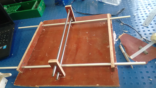
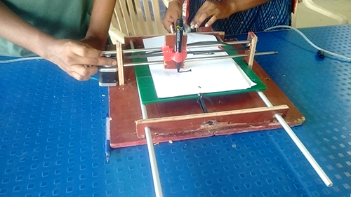
We are all new to machine making and that is why we started with a simple X-Y plotter, we tried fixing motors and accuator to it.
We got a lot of insights from this, now we move on to making the real machine
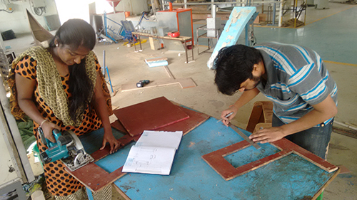
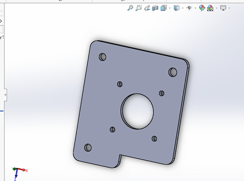
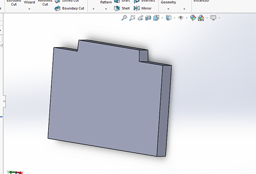
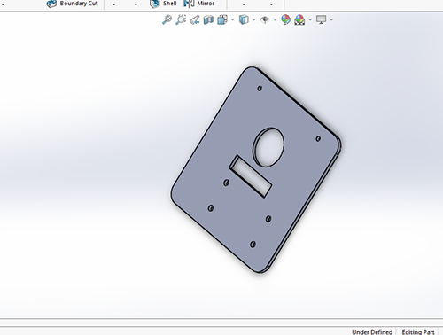
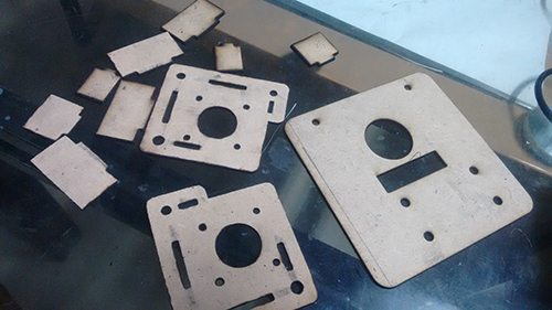
After these two versions we made the final mechanical design of our machine in Solidworks
We cut the parts in 3mm MDF, most of the joints were press fit
Firmware and programming
We went through some previous projects done by fabacademy students and also some available on the internet
The first part of my job was to decide what mechanism we are going to use for the machine. Our machine has a polar mechanism
Next step was to decide on the firmware and software that we are going to use.
Final step was to edit the firmware according to the hardware of the machine

Trail 1
Arundhati and Abhijeet did this task and dipali did the study of gcode
We started with searching firmwares and compatible boards for the same we found this on the internet
We at viyan Ashram Fab Lab have already tested with Marlin firmware on arduino mega with Ramps 1.4, thus we selected the same combination
As we were going to use arduino(mega/uno) we seleced Marlin firmware
we downloaded the firmware from the above website and used pronterface as a GUI and inkscape plugins to convert my files to gcode
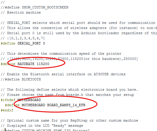
When you download the Marlin Firmware we have several files in our ectracted folder, we open the arduino file and switch to configuration.h file

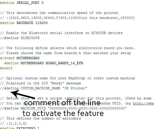
We have to edit the firmware according to our hardware, we have several options to edit such as baudrate,motherboard etc.
We can comment or comment off the features in the firmware that we want
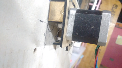
After the firmware was successfully uploaded on the arduino, we connected our motors to the board.

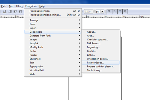
we connected the x and y motors we did not connect the servo as of now, then we got the gcode from inkscape for this we have to download a plugins for inkscape from here
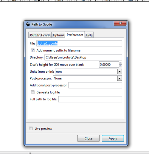
After the plugins are installed we can generate a gcode of the object in inkscape by going to extension option and selecting path to gcode, here we can tweak some options and save the file to the prefered location.
Next we open pronterface and connect the arduino with the pc. After this we select the baudrate and the port and hit connect.
Load the gcode that we did in Inkscape and hit run.
The two motors that I connected starting moving at a very high speed and in a random order, we paused the printing and gave it a direction in X and Y direction seperately but still it behave abrupt, we started digging onto the configuration.h file we realised that the core x y mechanism was commented off this meant that the machine was running a core x y mechanism and thus when we moved the x co-ordinate both motors started moving.
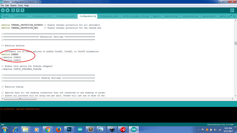
My machine was not using core x y mechanism, we started searching on the internet and found out that Marlin supports Cartesian, Core x y, Delta and Scara mechanism our machine did not have any of these mechanism, ours was a Polar mechanism
Besides Marlin has a lot of features related to heating and temperature which were not anticipated in our machine Thus commenting these features gave a lot of errors while compiling the code
Marlin firmware was specially made for 3d printers and most of the features were not needed in our machine thus we decided to switch away from Marlin
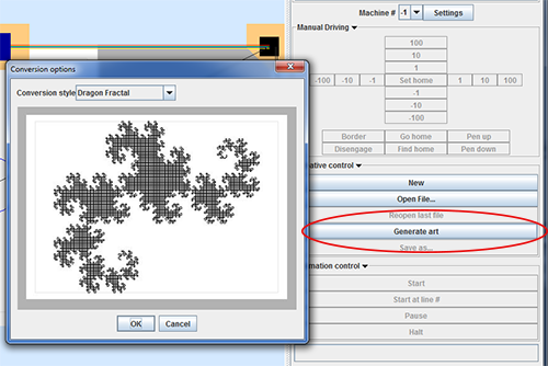
we came across these two polar bots which are on similar lines with the machine we are building PolargrapghSD and Makelengelo
The firmware and the software are available on the git hub website, and we thought of giving it a try.
Trail 2
we started first with PolarBotSD, the docmentation of this particular Bot is very well written, the forums are also very discriptive.
Polargraph is compatible with arduino Mega with Ramps 1.4 which we alrady had, thus we uploadeddownloaded their latest version of the firmware and uploaded it to the board.
But the firmware of PolargrapghSD wont compile in arduino

This code could be debugged and updated, but we switched to Makelengelo firmware which uploaded without any error on arduino uno. Makengelo is not compatible with arduino mega 2560, thus we shifted to arduino uno
Trail 3
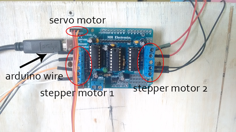
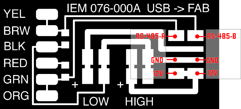
Now that the firmware is uploaded on the board we were ready to make the connections, we are using
arduino uno with motor driver shield, the connections are as follows.
Abhijeet works-I make this webpage thats why I use I here
I connnected 12V 1.2amp external power supply to the board, the motor are also using 5v from the arduino board
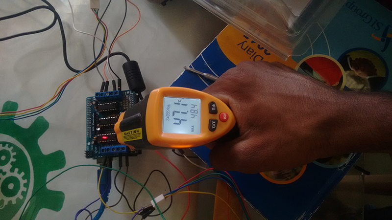
After I connected the power supply and the motors are moving fine as I move the X and Y co ordinate of the machine, but the IC on the shield heat up very quickly
Besides the servo motor keeps on moving continuously, this is not recommended as the servo is going to command the position of the pen, it is going to decide when the pen is going to tuch the canvas and when it is slightly lifting awa from the canvas
I disconnected the powersupply and tried running the motors on the arduino power supply itself
I also checked the temperature on an IR temperature sensor this temperature is well within the range
I disconnected the servo motor from the board, and tried running the machine without it.
Arundhati make the bill ofmaterial she purchase and order the material from market
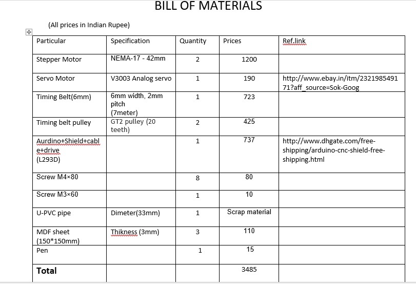
Bill of material
Scope of improvement
The machine is frameless, in order for it to paint the wall we need to try out vaccum pads
We have to do mechanical calculations such as pulley diameter, steps per revolutions and other things and update them in the firmware for better resolution of the machine.
The servo motor problem still persisits, we need to trouble shoot it in the firmware.
Firmware editting is major scope for improvement, we have to explore every line in the firmware to know its end effect.
Counterweights have to be accurately counted for better gripping of the belt
The motor mounts and the penholder still lag stiffness and strenght, we need to redesign them
conclusion
Nice experiance while working in group we learn alot things from each other and we made no. of trials on the different mechanism.