| | video file |
 | My designed part | STP file | STL file |
 | The vax mold | STP file | TAP file with all toolpaths, works in Mach3 |
 | The whole project | F3D (fusion360) file |
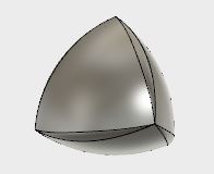
I have been fashinated with non-spherical objects of constant width for some time now. So I will design one and cast a few.
These are solid objects that have the peculiar abilitiy that they "act" round while not being round.
Here is a video illustrating their properties
The ones in the video are revolved from Reuleaux triangles. However, since they are revolutions of a 2D shape, they have a rotational symmetry which I find lessens the potential "wow-effect". A more interesting kind of solid of constant width are Meissner bodies or aka meissner tetrahedron. Here is a video demonstrating those:
However I was as bit dissapointed that the edges on the Meissner bodies aren't the same, rounding of three edges out of 6 sounds to make them roll feels like cheating. I researched further and found out that you can design a solid of constant width that has full tetrahedral symmetry and all the same edges. I haven't found a specific name for these yet but this is a really good site showing how they work.
External page with presentation of a Spheroform Solid with Tetrahedral Symmetry PDF backup of the proof
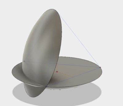
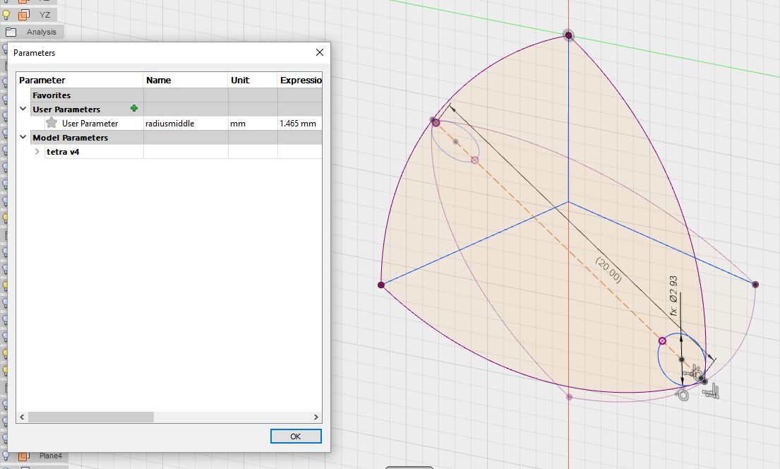
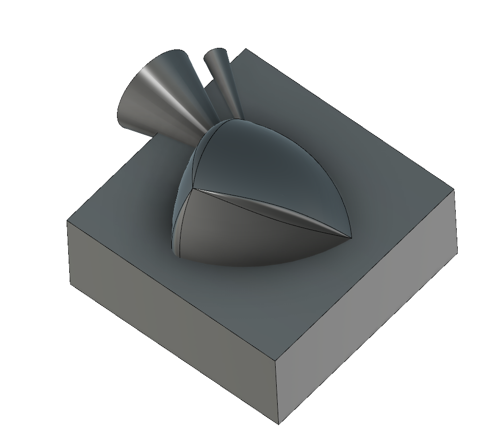
I designed my spheroform in fusion360 using revolved surface patches and fillets with variable radius.
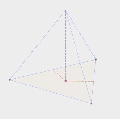
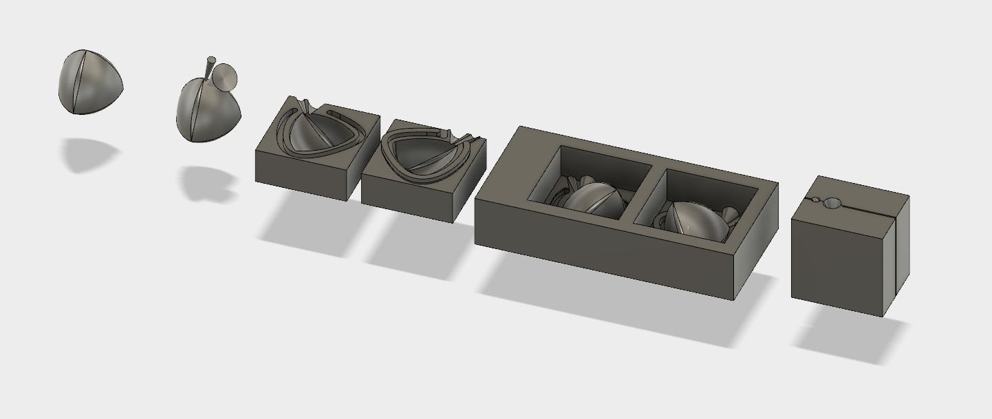
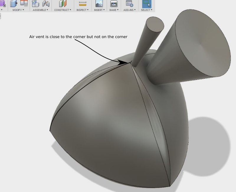
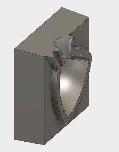
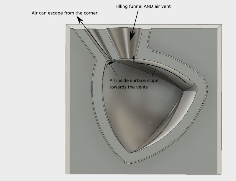
I started with modeling a funnel and air vent in strategic place on a surface that will be easy to file smooth. I oriented them so that air should not be trapped anywhere.
I oriented the split-line or mould-divison line so that there would be no overhangs. This is important both for me to be able to mill the vax on a 3-axis machine and and so that the cast mould and objects would be easy to remove. In my case I could use a flat dividing plane. If I had made a more irregularly shaped object I would have had to use a more complex dividing line to remove all overhangs and still be able to reach all surfaces from straight above.
I modeled a box to represent the first mould half, instersecting the model where I wanted the dividing line to be.
I then added an offset rim to the mould so that the mould halves would interlock, like the example Niel showed of the Tippy top mould. Note that this keeps my parting line in the same place. I also took care to make the offset big enough to fit the 3mm mill I used.
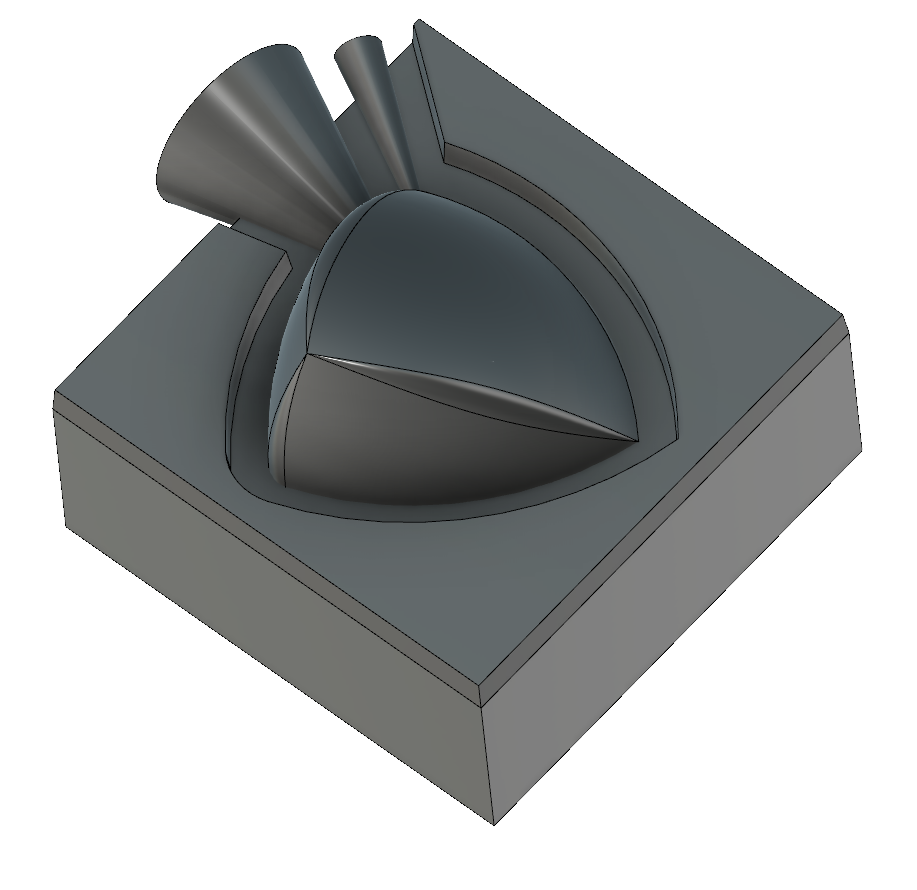
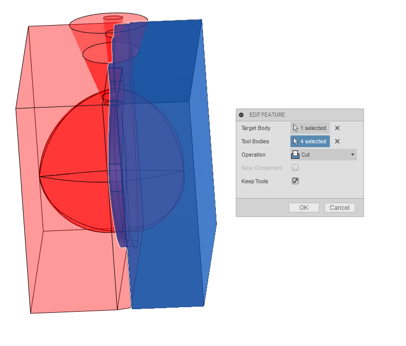
I used the boolean opeation "Combine" under "Modify" to make my object model cut a cavity in the first halve of the mould.
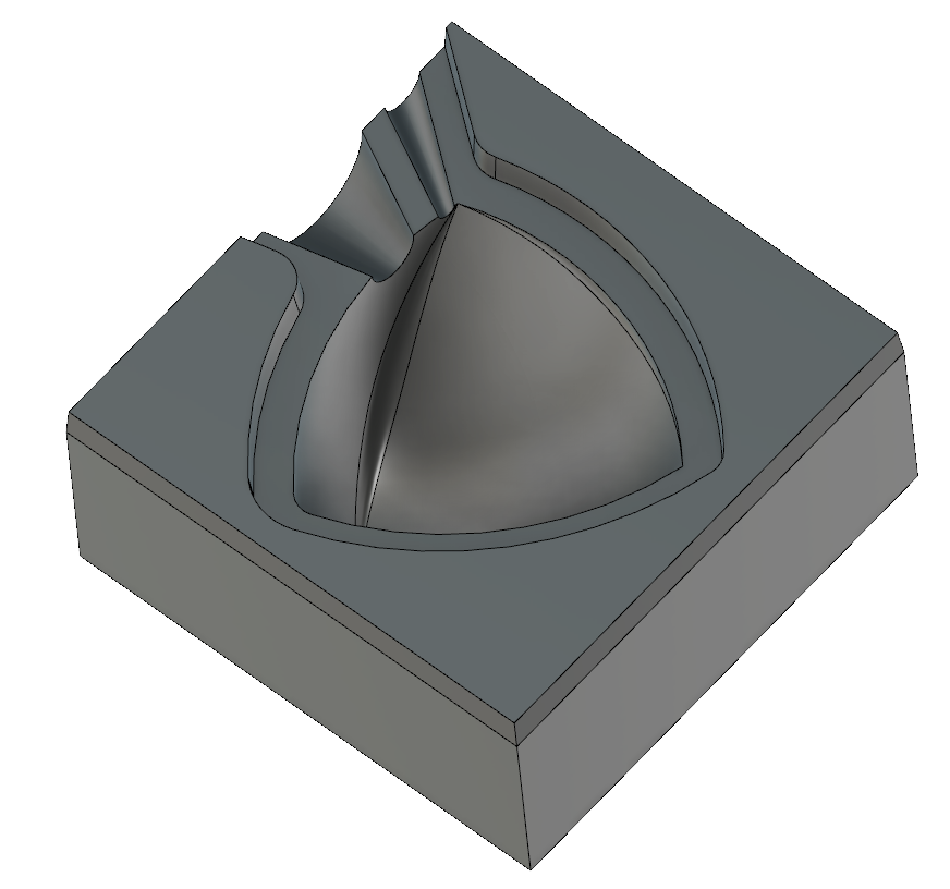
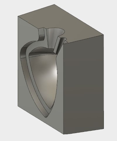
I then modeled the other halve of the mould, starting from the parting line
Then I used Combine again to cut the new mould halve to match the object and the first mould halve.
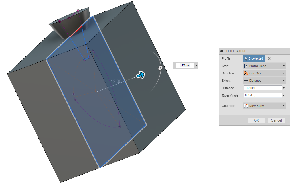
Then I gave the moulds outsides a release angle of 5 degrees (to let the silicone release from the machined vax cavity) on all faces except the bottom faces since I wanted it to stand flat on the ground.
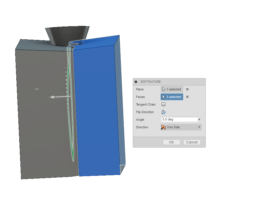
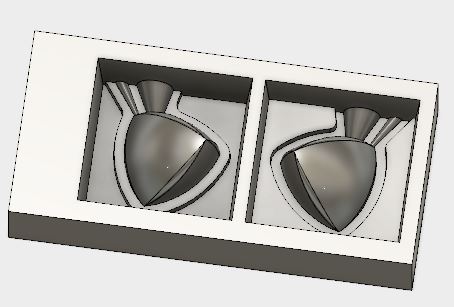
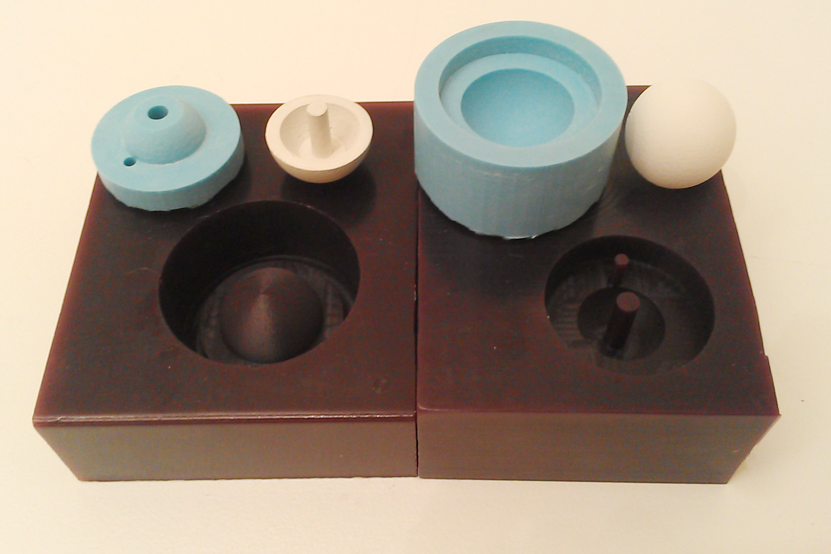
Here you see the silicon mold halves with the added a rim aroud the split line and the 5 degrees draft angle to make it release more easily from the wax mold. Tip: this can be done either directly in your "Extrude" feature as a "Taper angle" setting or with the "Draft" feature under the "Modify" menu.
Then I reoriented the silicone mould halves to cut cavities into the machinable wax block using the same "combine" funcion.
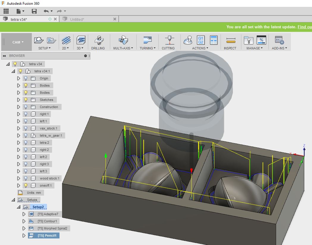
I used the CAM model in fusion to set up the toolpaths, I did all machining with a single flute Ø3 mm endmill on the SaleCNC.com full size router controlled with a windows laptop running the Mach3 CNC control software.
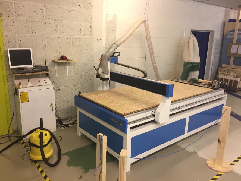
The whole milling job took 47 minutes.
I started with doing some test machining in wood, here I used 9 mm pass depth and kept the rest of the settings the same.
.jpg)
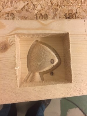
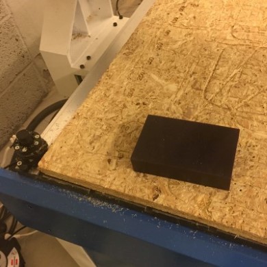
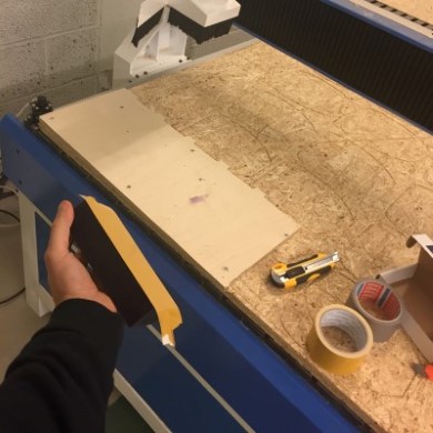
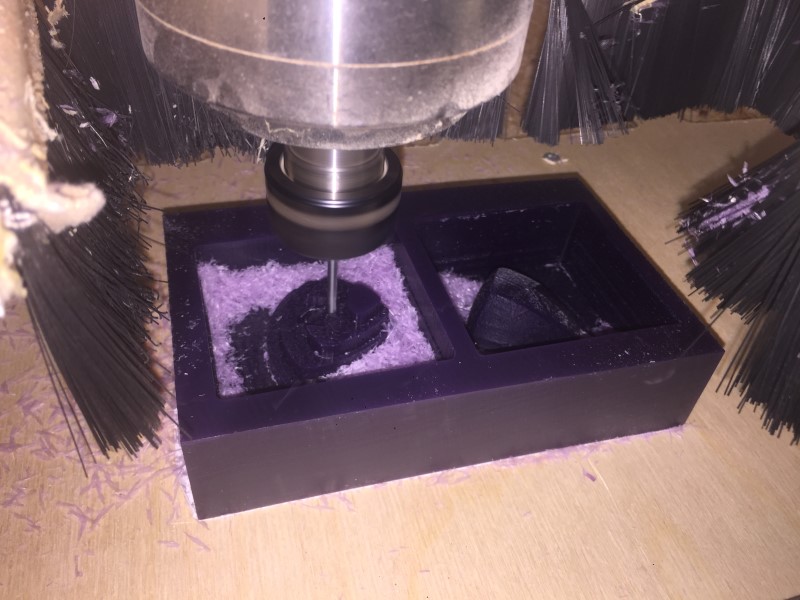
Time to machine the vax! I screwed a fresh plate to the spoiler board to get a flat clean surface and attached the vax to it with double sided tape.
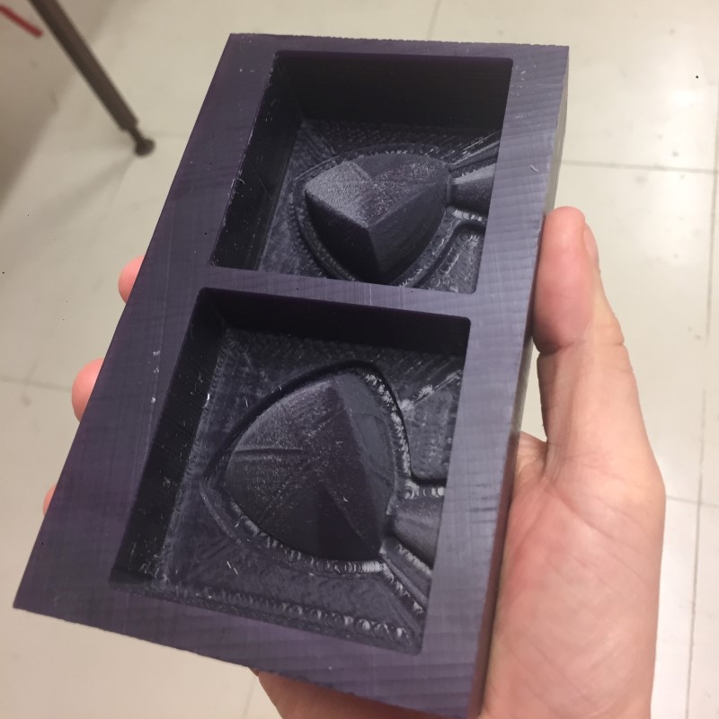
The milling worked fine, the only issue was some small toolpath radiuses on the surface that showed up in the vax. They were too deep to rub out easily afterwards (tried with a cloth). It is possible that they could have been avoided if I had used a lower feed speed.
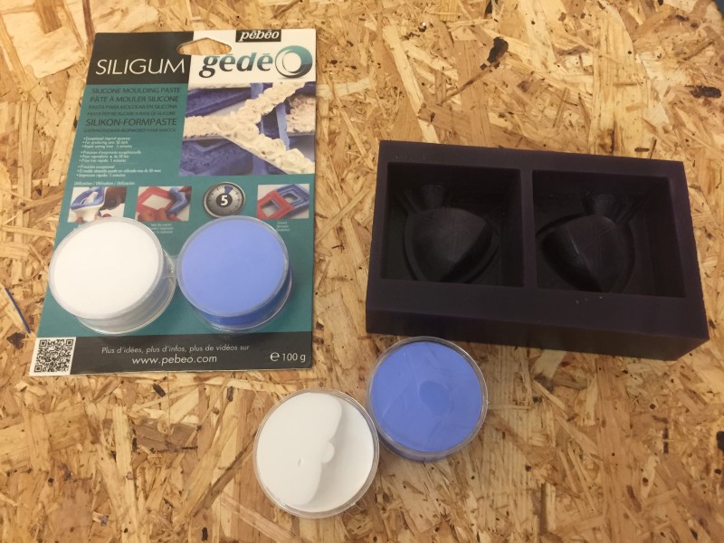
I used 200g Siligum silicon molding paste from pebeo.com. (horrible website) It is a thick paste that you mix by kneading the two components together.
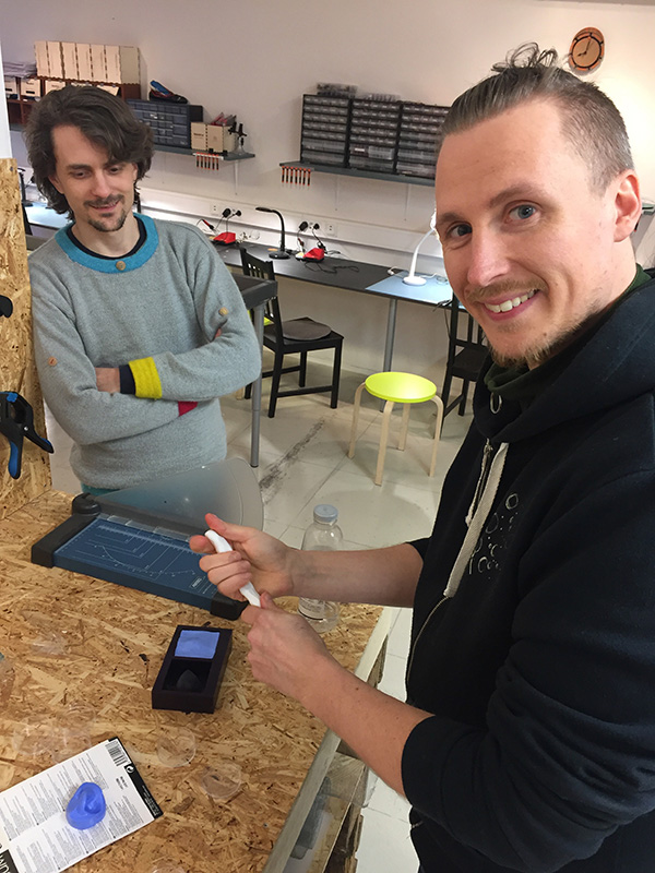
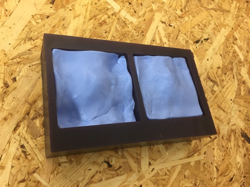
I tried to let all air escape while pressing it down into the cavity but ended up trapping quite a bit anyway, especially in both of the "peaks" where I didn't anticipate it.

When test-fitting the mold halves I noticed that the guide lip alone didn't stop relative movement very well, but since the bottom surface was made flat it was still easy to align them. It would be interesting to make another one with guide pins or "spokes" and see how they compare.
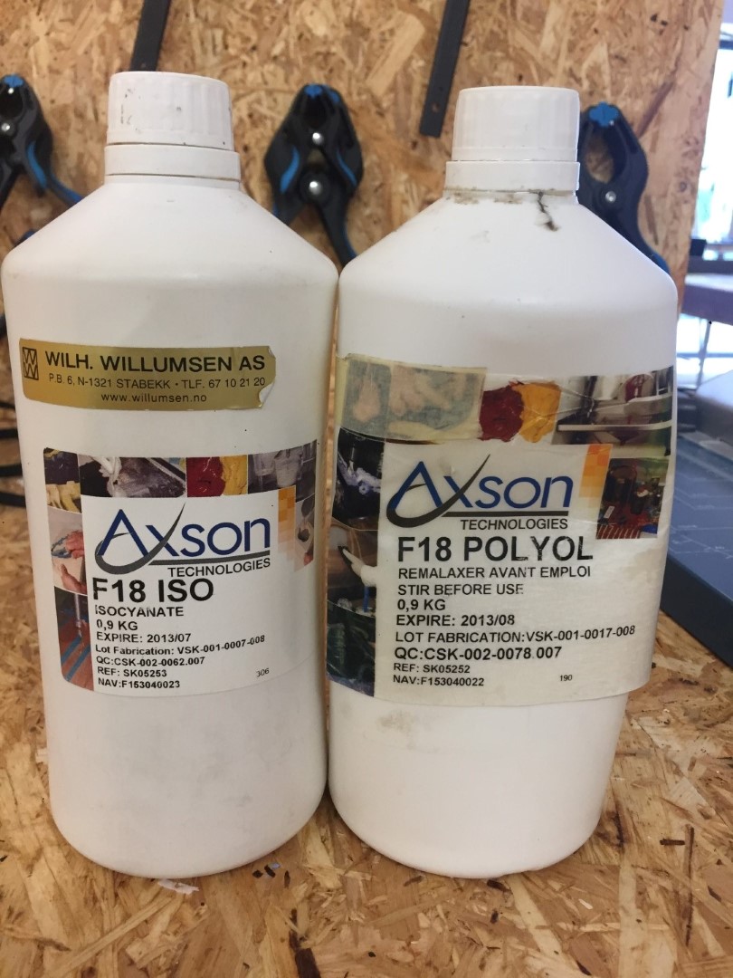
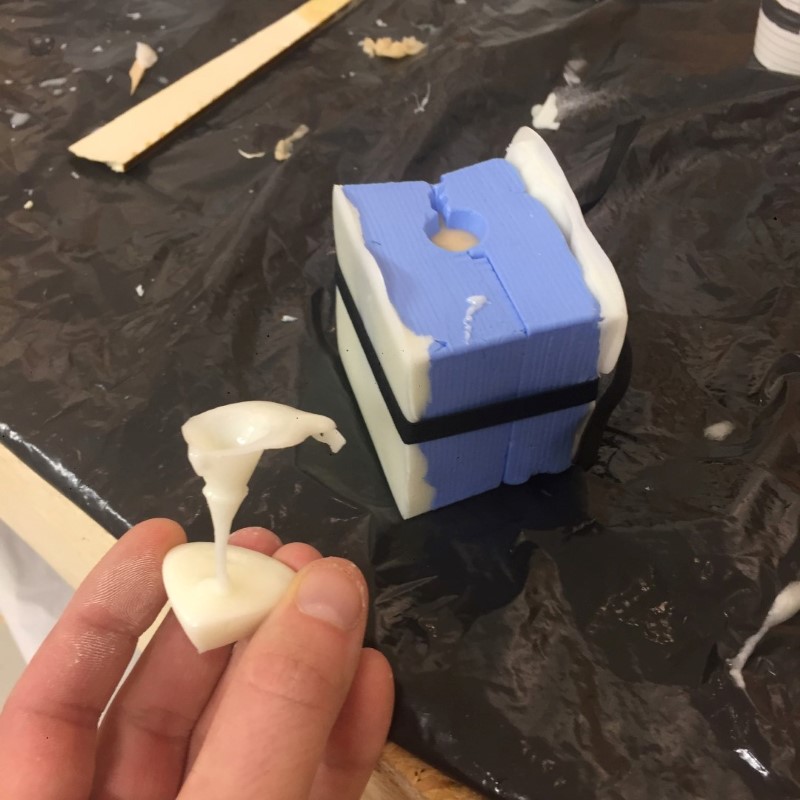
For casting we used two component polyuhretane which expired in 2013 so our instructor Jens made a test in a lab glove to see that it still was useable.
The test worked fine so we proceeded to cast our components. I used resin cast backing plates to eaven the pressure from the rubber-band we held the molds together with. Here I have waited too long before pouring and ended up with a clogged funnel.
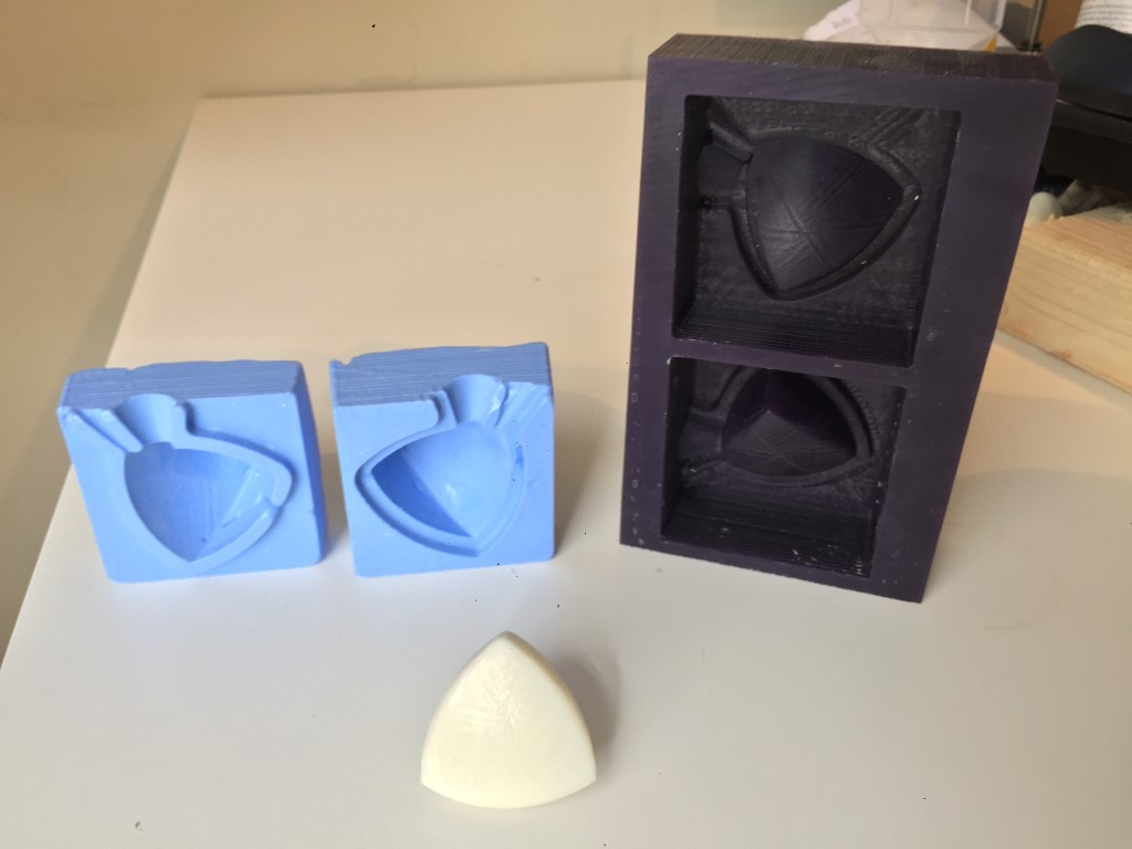
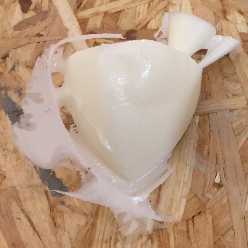
This was the most succeesful attempt! The likeness to a heart is unintetional.
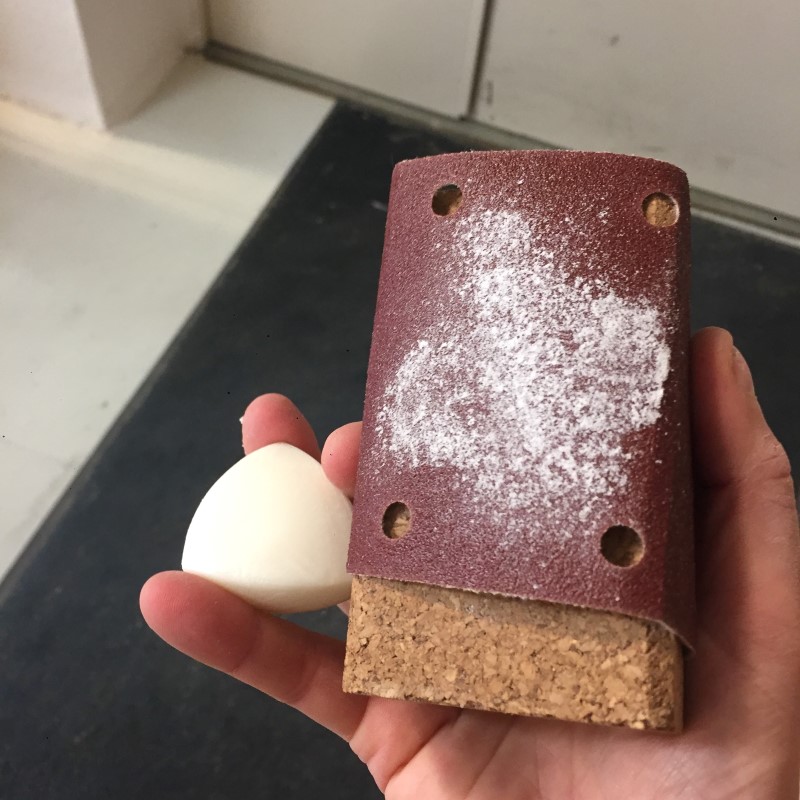
I trimmed of the excess with a carpet knife and sanded down the irregularies which took quite a while an probably will effect the "constant width" behaviour of the object that I was after.
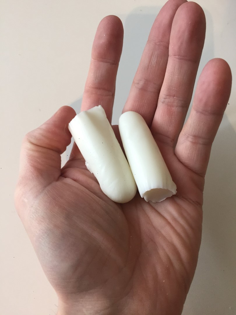
Time for the "hero shot"!
Now I would like to make more, at least two, so that I can replicate the video demos above. Hovewer I would like to improve my mold so that I don't have sand out all the bumps from the trapped air.
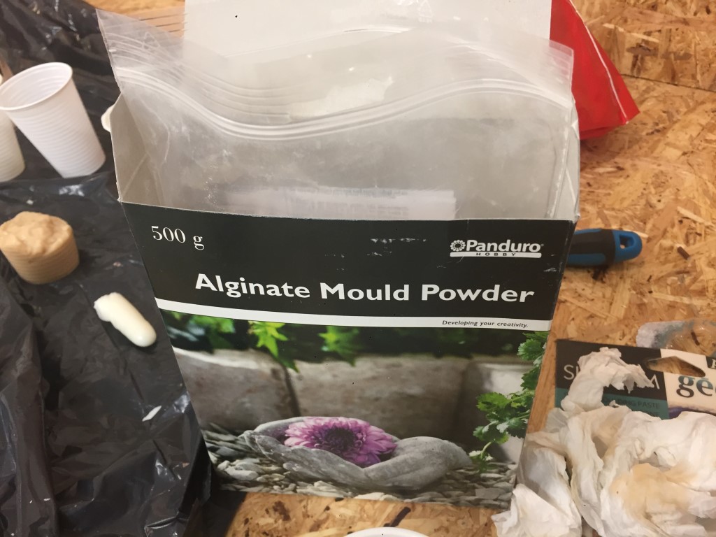
Since I got significant air bubbles in my silicone mold I wanted to make another attempt. However we had no more silicone mold material. So I tried to make new molds out of alignate. Alginate is an algae based mold making material that comes in a powder which you mix with water. It is primarily used for making molds of body parts (life casting) since it is harmless to touch. Its consistency when cured is somthing like a wet pudding.
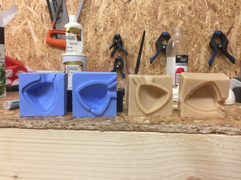
My first attempt at alginate molds. They ended up having quite a bit of clumps of unmixed powder visible in the casting surface. (Silicone as a reference to the lect and the alginate molds are to the right in the picture.)
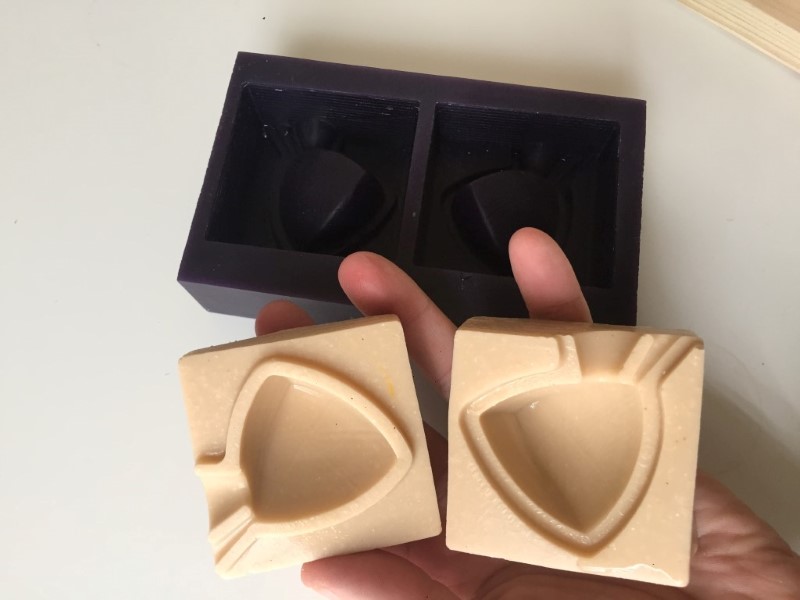
My second attempt, this time using a strainer to remove clumps and a brush to remove bubbles. Much better surfaces but they are still very wobbly.
Note that they are always wet, the alginate seems to constanly "sweat" water and this actually changed the surface texture of the casts, making it look a bit molten.
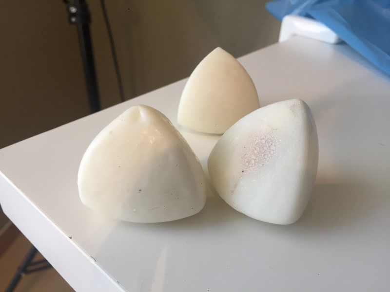
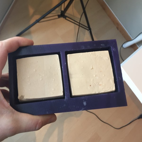
The front of the above picture shows two cast in made in the alginate molds and in the back is the one made in the silicone mold. The alginate molds were too thin to retain the shape and the casts ended up deformed even when I used plywood backing plates to steady the molds while casting.
I could design a wooden cage, changing the mixing ratio or try reinforcing the alginate by casting in mesh or fibres. I am convinced I could make it work, but whatever I do to improve them they would still only be useable during one day since they loose moisture fast and shrink.
Shrinkage of the alginate molds after one day of storage.
I want a lasting mold with good repeatablillity. So I started looking into other alternatives.
I would like to try the OOMOO silicone mold making rubber from Smooth-on or some other two component pourable silicone. However I found out that our lab will not order any this year, so I tried to come up with a DIY alternative.
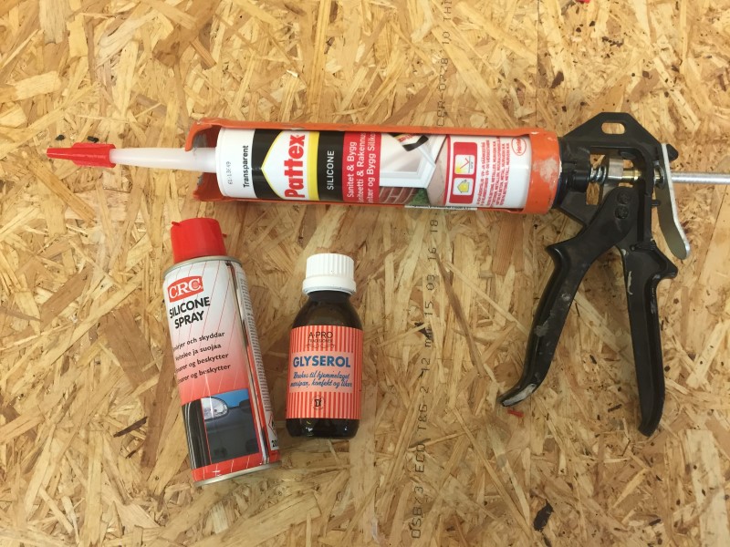
I have seen several youtube videos and instructables thay show that you can use either glycerine or soap water to accelerate the curing time of pure silicone caulk, the kind that is typically used for sealing windows and such.
I also had an idea that I could use silicone spray oil to either wet the surfaces I wanted to coat or mix it into the caulk to reduce the viscosity and make it easier to work with.
So I went shopping in a hardware store across the street. I tried to make sure I got a tube of pure silicone but later I found out that my "Silicone" might be a "MS hybrid polymer" which differs chemically from the pure silicone I wanted :(
Safety data sheet for the tube I bought. This is my only hint to what actually is in the tube.
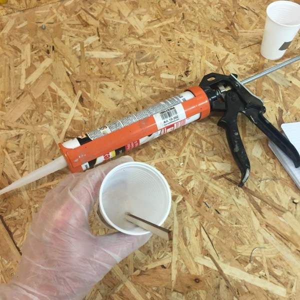
I made a list of test I wanted to run and mixed up small batches in lableled disposable cups.
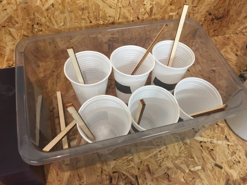
The videos I had seen had given me the impression that a drop of glycerince would cause the silicone to harden through in minutes, and I hoped the oil would help me make the silicone easier to apply.
| Mix | Initial Consistency | Stiffness after 1h, 1=stiffest | Surface after 4,5h | Observations after 33h |
|---|---|---|---|---|
| No addative | Very sticky, clear. | 4 | Sticky but does not transfer to finger | Typical silicone, little bit sticky surface but feels cured through, thickest part 3 mm. good surface, quite soft some bubbles. Released semi easy. |
| Glycerine (1 drop) | White-ish, sticky. | 2 | Sticky but does not transfer to finger | Harder to pull out, otherwise exactly as pure but whiter. |
| Silicone spray oil on the walls | At fist the oil prevented the silicone from sticking to the walls but then it got absorbed by the silicone. | 5 | Sticky but does not transfer to finger | Similar to pure. Harder to pull out? |
| Glycerine + Silicone spray oil | White-ish, sticky after stirring. | 3 | Sticky but does not transfer to finger | Similar to pure but whiter. Hard to release. |
| ~1 cm^3 silicone spray oil | Much more runny, almost pourable. | 6 | Sticky and transfers to finger | More bubbles, easier to pull out, little bit more sticky |
| ~4 drops of glycerine | White-ish, sticky. | 1 | Sticky but does not transfer to finger | Would not pull out, even whiter. |
Additional tests, running
Made test in Hannes mold of oilmix and pure. Made attempt with lifting screws with washers in mine, plenty of silicone, should wait a week at least for it to cure. put it in 28/4.
UPDATE:The test wasn't a success. I could not remove the silicone without it tearing apart.