What is CNC Machine ?
CNC Machining is a process used in the manufacturing sector that involves the use of computers to control machine tools. Tools that can be controlled in this manner include lathes, mills, routers and grinders. The CNC in CNC Machining stands for Computer Numerical Control. On the surface, it may look like a normal PC controls the machines, but the computer's unique software and control console are what really sets the system apart for use in CNC machining.
Under CNC Machining, machine tools function through numerical control. A computer program is customized for an object and the machines are programmed with CNC machining language (called G-code) that essentially controls all features like feed rate, coordination, location and speeds. With CNC machining, the computer can control exact positioning and velocity. CNC machining is used in manufacturing both metal and plastic parts.
First a CAD drawing is created (either 2D or 3D), and then a code is created that the CNC machine will understand. The program is loaded and finally an operator runs a test of the program to ensure there are no problems. This trial run is referred to as "cutting air" and it is an important step because any mistake with speed and tool position could result in a scraped part or a damaged machine.
There are many advantages to using CNC Machining. The process is more precise than manual machining, and can be repeated in exactly the same manner over and over again. Because of the precision possible with CNC Machining, this process can produce complex shapes that would be almost impossible to achieve with manual machining. CNC Machining is used in the production of many complex three-dimensional shapes. It is because of these qualities that CNC Machining is used in jobs that need a high level of precision or very repetitive tasks.
.
CNC Shopbot Machine
History of CNC Machine
Let's go in deep into the Work Flow of CNC Shopbot
Shopbot in detail
Neils Lecture summary !
Our assignment for the week was to make something Big ,Which means something useful to be designed and make that open and have to completly understand the mechanism behind CNC .
Shopbot:it is a large milling machine with end mills ranging from half of an inch to 1/8th of an inch. It is a 3-axis machine and has a bed size of 4x8 feet. That is "The Full Size PRSalpha CNC". The bead size of this machine is 96 x 48 which is approximately 8X4 foot, CNC is the short form for Computer Numerical control. The CNC machine works as per the programmed instructions fed into the controller unit of the machine. The CNC machine comprises of the mini computer or the microcomputer that acts as the controller unit of the machine. While in the NC machine the program is fed into the punch cards, in CNC machines the program of instructions is fed directly into the computer via a small board similar to the traditional keyboard. PRSalpha CNC is a 3 axis machine (X,Y,Z).
Some more specifics about the shopbot milling machine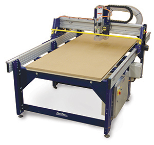
CNC Machine(Full Size PRSalpha CNC)
know more about the machine here
Resources For Good Designs and CNC Machining
There are Huge collection of Resources available one of them are my seniors and instructor Vishnu Easwaran EYadu Sharon M. G.Yogi Kulkarni by following their documentation i was inspired to make something cool for lab and i have tried to figure out what i can make for lab at first i have thought to make a Modular Table which is adjustable as per the members sitting but later i thought a bench outside for lab ,then finally as my instructor yadu was discussing any body intrested in making a projector stand , i have took the challenge and i have designed ,i have used the Rihno for designing the model and i also done the paper prototyping to understand how the design looks and these are the good resources here down :
Process of Settingup a machine
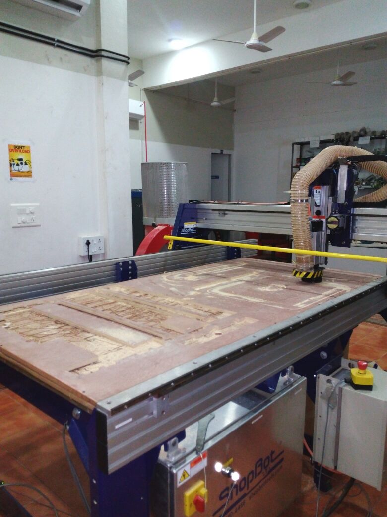
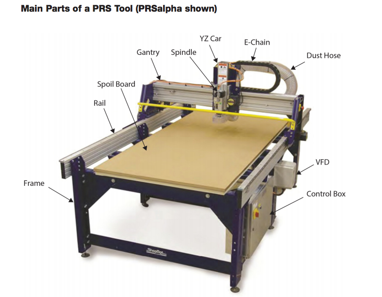
Inorder to Start working with shopbot, first we should know about the parts of the machine and operation of each. ShopBot PRS alpha 96X48 in our lab is showned below. The X,Y and Z axes are marked in the picture, the bed is having the dimension of 96X48 inches in X and Y directions and Z is 6 inches. Next we will go through each parts of the machine.
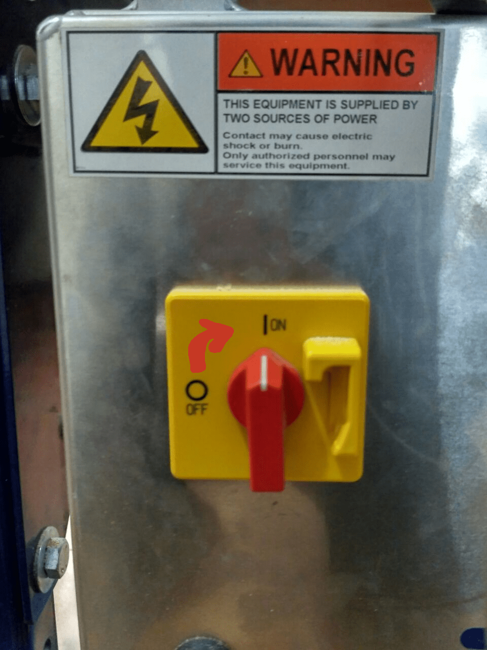
Machine ON/OFF switch
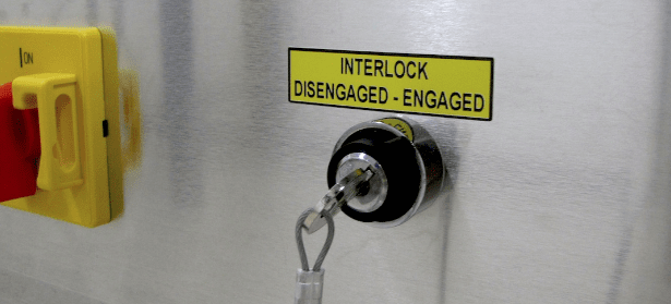
The ON/OFF switch is in the right side of the machine near to the control box.This acn be turned ON/OFF by simply turning the red colored knob from ON to OFF position as showned below. The machine is powered from single phase supply.and The interlock key is located on the left side of power switch, which enables the spindle. It is having a key at the end of Tooth Holder, inserting the key to the engaged position will activate the spindle.
Note:please Don't forget to keep the spindle lock open when the machine is not about to cutting ,only on the spindle when required
Emergency Stop ,Reset and Start Control
Emergency STOP switches are used for stopping the work during emergencies there are two emergency stop switches will be there,Ensure these ESTOP switches are in the OFF position position by rotating the RED STOP button on the DONGLE COUNTER CLOCKWISE
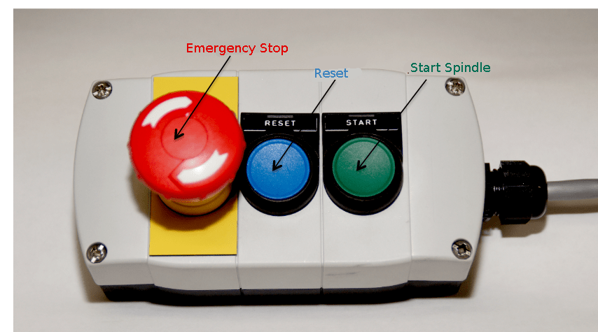
The Reset switch is for the intial stage to have the clean MicroController and ready to process the data from the computers serial communication
The Start Button is for the starting the spindle before the process of the cutting starts and the spindle will be on only when the key for the spindle is ON start the process only the spindle comes to the required RPM in my case i used the 12000RPM
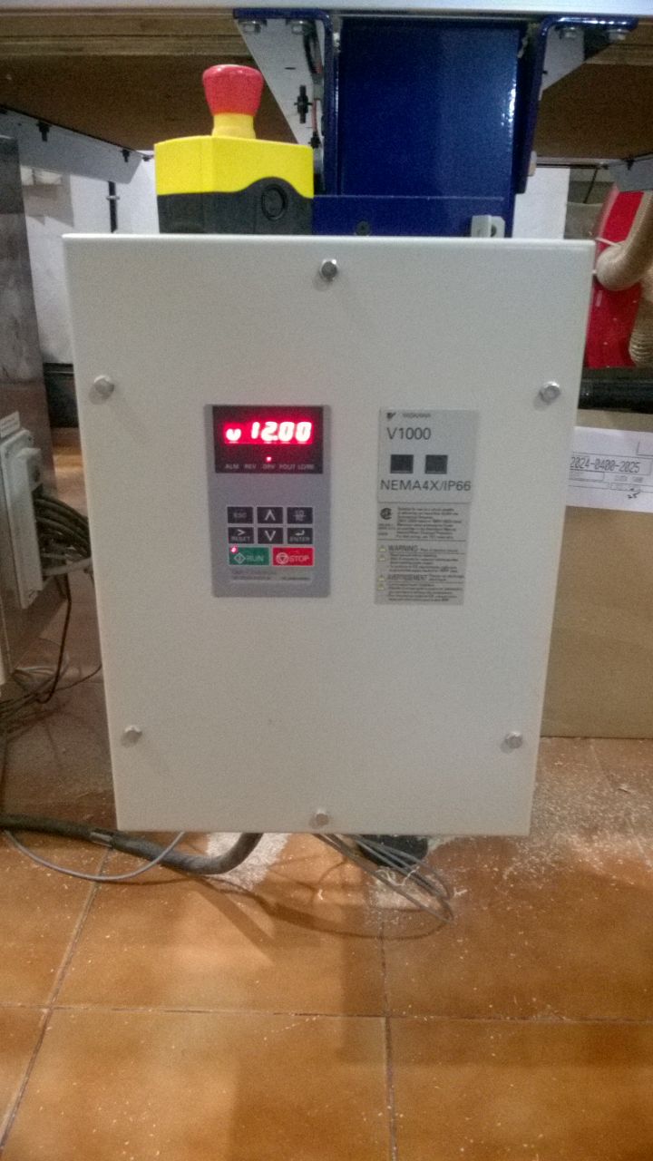
Spindle Control Box
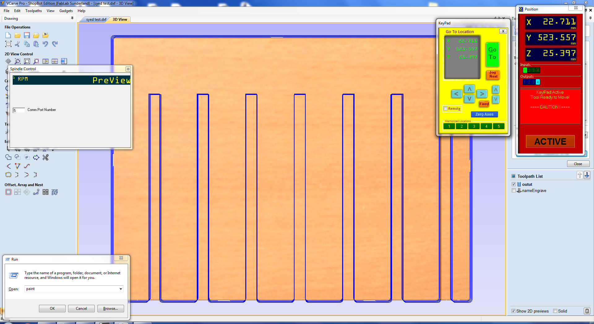
The spindle RPM control board aloows you to change the spindle rpm using the software. The controller is wired into Variable Frequency Drive (VFD) models and is connected to PC via USB. We can manually udjust the spindle speed by pressing the Up/Down arrows in the panel display. The figure below shows our control panel working on 12000 RPM.
Required Tools and Softwares
The following tools are required to operate on Shopbot machine
End Mills
An end mill is a type of milling cutter, a cutting tool used in industrial milling applications. It is distinguished from the drill bit in its application, geometry, and manufacture. While a drill bit can only cut in the axial direction, a milling bit can generally cut in all directions, though some cannot cut axially.End mills are used in milling applications such as profile milling, tracer milling, face milling, and plunging. The material of the bits are made on different materials, most common are solid carbide bits.
Flute types: There are four basic flute types: Straight, spiral up -cut, spiral down-cut, and compression. Each type has its own advantages and disadvantages, which are outlined in the chart below.
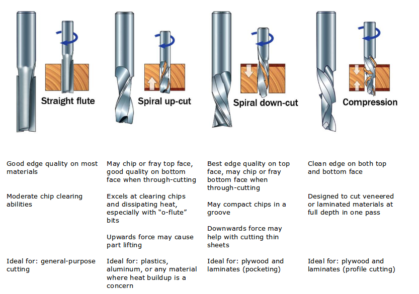
Number of flutes:The number of flutes on a bit is essential to calculating proper feed and speed rates.For most applications you can use a bit with 1, 2, or 3 flutes, but you must adjust your reed rates and RPM accordingly to maintain proper chip load.
End shape:Straight and up spiral bits come in a variety of end shapes Square ends are most common, and are a good choice for creating pockets and grooves, profile cutting, simple lettering, and drilling operations. Ball (or rounded) ends are best for 3D carving. V-carve bits are often used to create complex letters for sign making. They can also be used to chamfer edges and create countersinks for screw holes.
Chip Load:Chip load refers to the actual thickness of the chip cut by each revolution of the cutter. It is the measurement that all feed/speed calculations are based on. A spinning bit generates friction and heat as it moves through the material, and part of this heat is pulled away by the flying chips. A larger chip load pulls away more heat, but also puts more stress on the cutter.Each material has its own ideal chip load range that balances heat dissipation with cutter stress. View More
Chip Load = feed rate ( ipm ) ÷ ( cutting rpm x number of cutting edges )
Some of the bits we are using is showned below
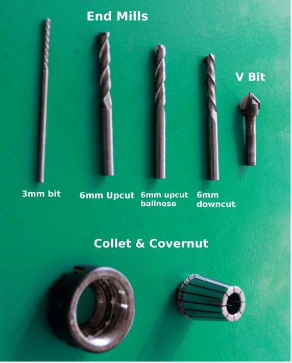
These are the bits and collets available(pic credits Ajith Kumar MG)
Collets& Covernut
A collet is a subtype of chuck that forms a collar around an object to be held and exerts a strong clamping force on the object when it is tightened.It may be used to hold a workpiece or a tool. We are using ER25 collets,ER collets are slotted (alternately) from both ends and therefore compress onto the cutter along the whole length of the collet when tightened. This not only provides a better grip on the cutter shank but also allows some variation (typically 1mm) in shank sizes that may be used in a single collet. The smaller size collets are best used to hold cutters no more than 0.5mm below the nominal size. Collets are inserted into the covernut.
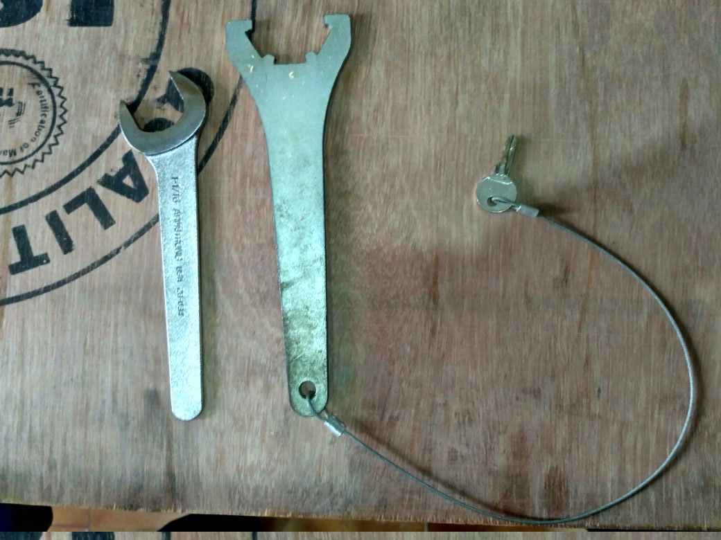
Wrentch & Tooth HolderWrentch & Tooth Holder: Tooth holder and wrentch is used to tightening the collet in to the spindle, you can identify them easily, tooth holder will have a key tied to it .
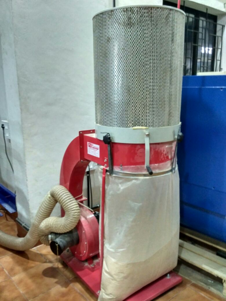
Dust collector
The dust collector is the most important tool as the removed chips by the CNC are very small and very sharp for the metal so it is the tool which imediately cleans the debris
Partworks software
PartWorks and PartWorks 3D are ShopBot-specific versions of Vectrix’s V-Carve CAD/CAM software that will get you started quickly designing for CNC cutting and machining. It allows anyone with a ShopBot CNC tool to quickly and easily incorporate beautiful, decorative carved designs into their own products, for 2D cutting we are using V-carve Pro and for processing 3D model we are using Partworks 3D.
ShopBot3 software
ShopBot3 is the control software for shopBot CNC, all the X,Y and Z axes movements and job processings are done through this control software. we can easily take the software from the start menu by clicking the ShopBot3 icon as shown below.
This all about the shopbot in detail now lets go to design the job to cut over the Shopbot
Softwares used to Desing the files
This week i have wasted time what to design and make on the Machine Controllered Cutting Week and i had a quick discussion with the instructors to make the projector stand for the lab , then i have started thinking how to make the stand i have opted to go to remodel the existing computer table to house the stand ,i had rough drawings and then figured out how to design
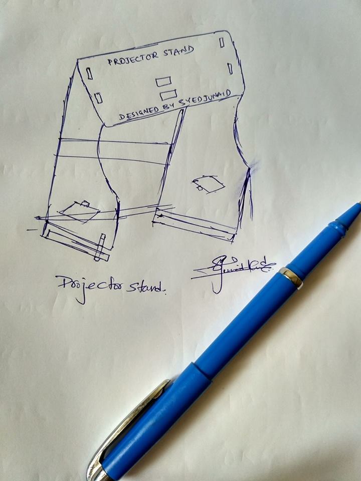
Rough diagram of the concept
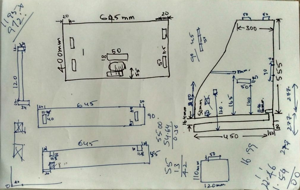
Rough diagram for the claculations of the dimentions
Then most confsion state i know working on the AutoCAD ,but my PC is running out of space to install new softwares i have already had the rihno installed for the testung and learning it as it little similar to the AutoCAD then finally dared to design in the rihno and came to the final design shown below and i have also 3D modeled and uploaded in the sketchfab
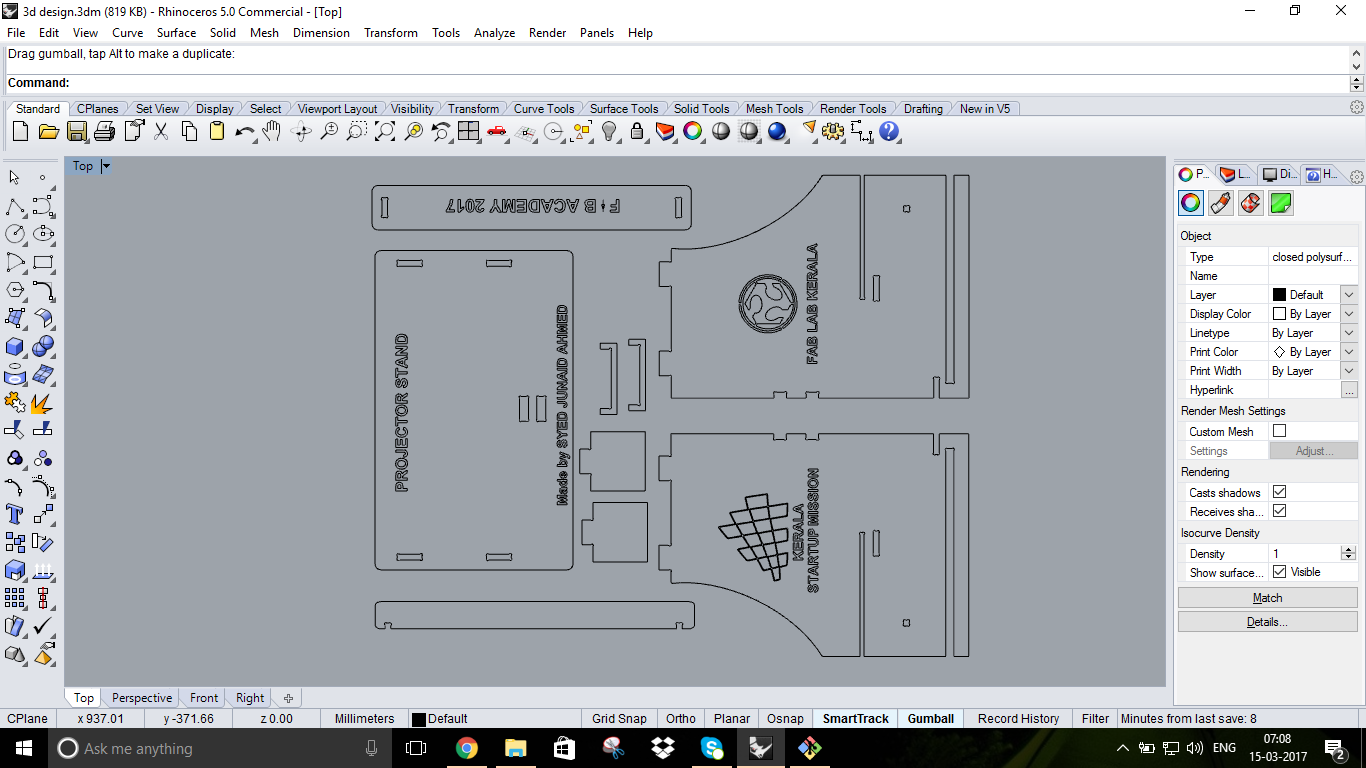
Designed in the Rhino
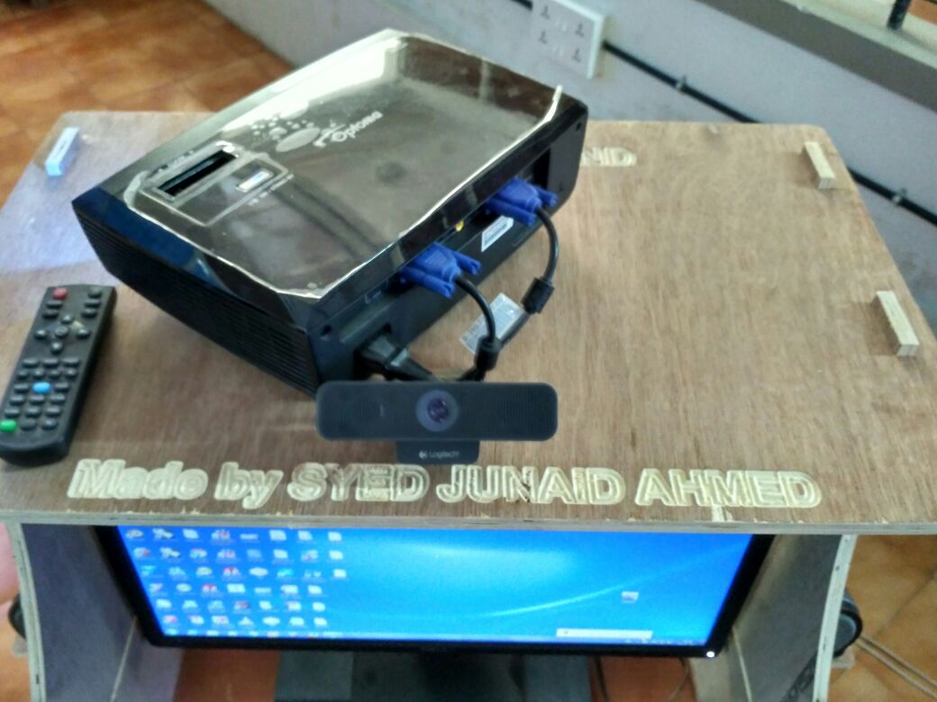
i have took the logos from the Ajith kumar as he has already made them for his job so i can re produce the same (i.e; Startup mission logo and fablab kerala logo)
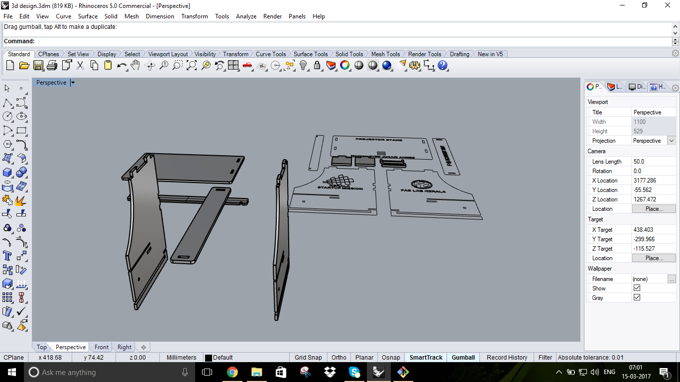
3D modeling in the Rihno
Thus i have done with the designing and i have moved to the final cutting process
you can download the CAD Design files and VCarve setup fileshere
Work Flow of ShopBot
Till now we have learned alot about the CNC machining but now we are going to handle the real machine ,before going to work with we should understand some Do's and Don'ts
Do's and Don'ts
Things to Do:
You Should wear ear protection while working You Should wear closed-toe shoes at all times. You Should wear eye protection when working with tools as it is involved with wood chips or sawdust You Should tightly bound any loose items on your body(i.e long hair,scarf e.t.c) that might get caught in moving machinery. You Should make small cuts at slow speed otherwise you will risk breaking the cutting tool, and ruining your material You Should react immidately in case an operation fails and press emergency stop button You Should make sure the spindle collet and cover nut are properly secured and not over-tightened. You Should always use a sacrificial layer under the material you are cutting, so as not to cut into the table below You Should ensure the End Mill is fastened securely inside the spindle collet, before starting your operation You Should be very careful observation and sound to keep yourself aware of the operational conditions of the ShopBot for safe use The Don'ts are:
You Should not leave a machine unattended while in operation You Should not work alone while working with machine You Should not touch materials and chips being cut since they can be hot You Should not wear or have any loose objects on your body while operating this machine Setting up the machine
Things to Do:
The Don'ts are:
You Should not leave a machine unattended while in operation You Should not work alone while working with machine You Should not touch materials and chips being cut since they can be hot You Should not wear or have any loose objects on your body while operating this machine Setting up the machine
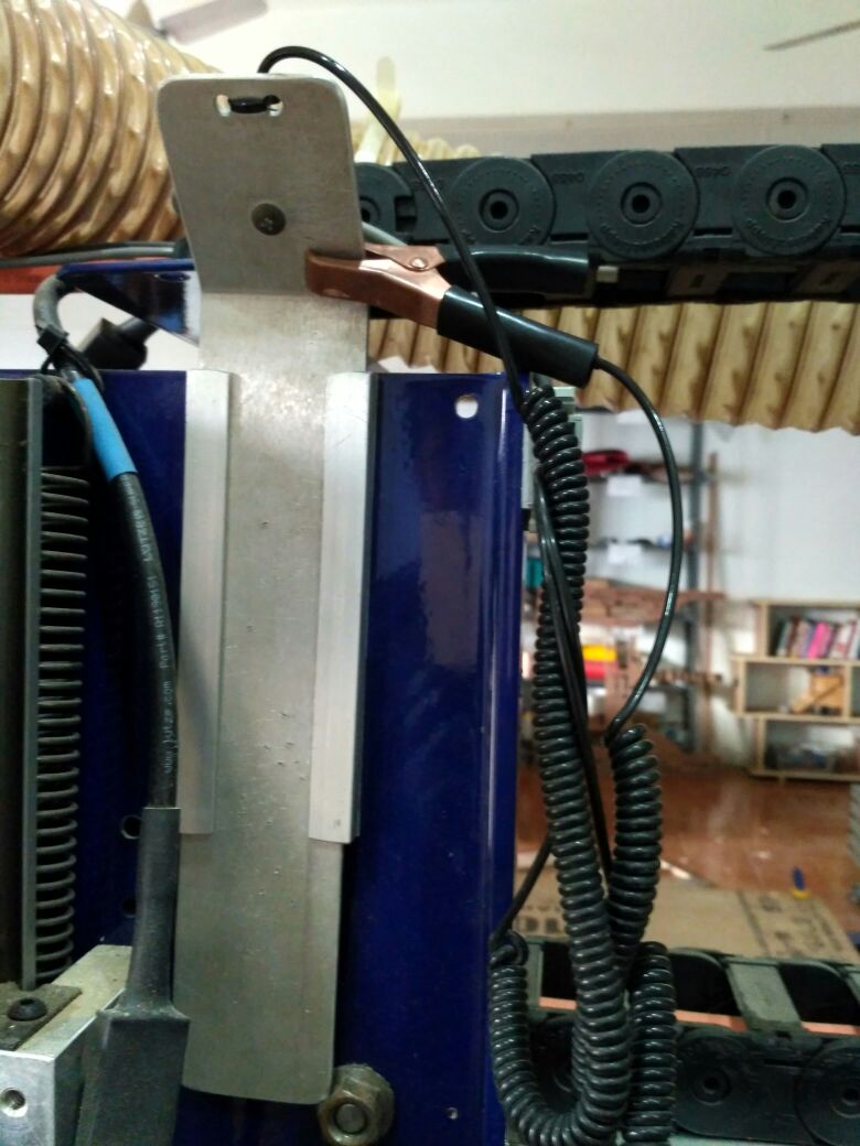
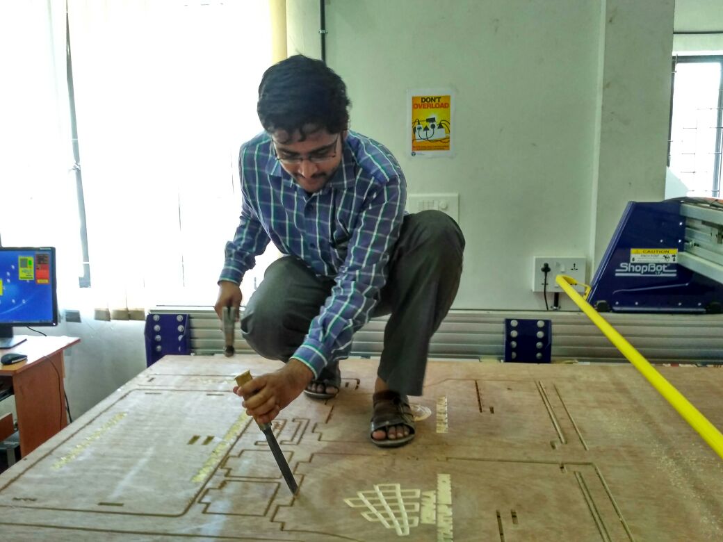
Once we are ready we have to do the cutting we have to fix the plywood to the machine on the top of the sacrifacil board not having any liftup or large curvers then we have to bring the spindle to the machine origin and then move it to the desired location where you want to perform the cutting and make the new origin and then use the z setting aluminum plate and aligator clip to set the z-origin and we have to send the .sbp file which we created loading a .dxf file into the vcarve software and setting the machine options
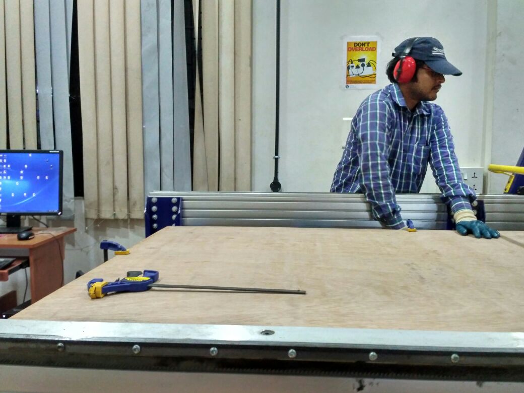
Setting up the ply wood for the machining
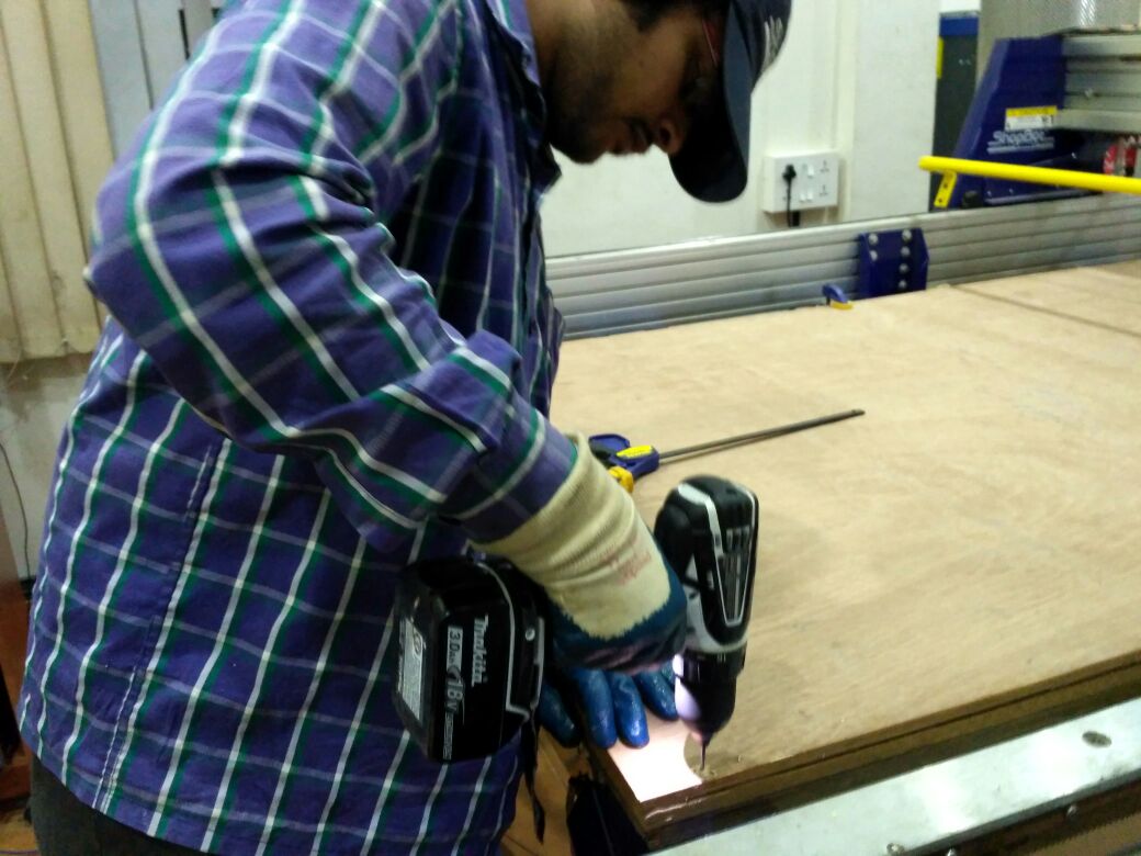
fixing the ply wood using the power drill and screwdriver
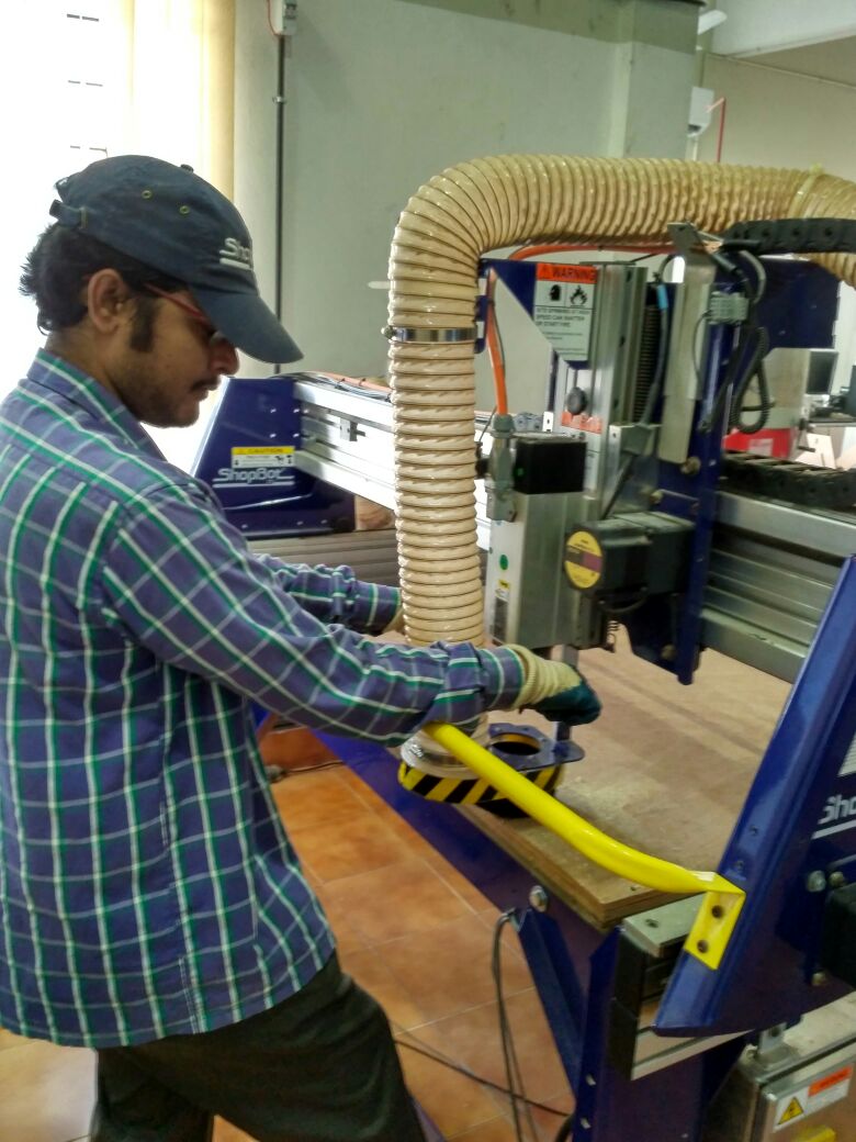
Setting up the drill bit for the engraving process
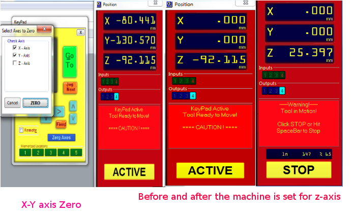
Setting up the x-y and z- axis
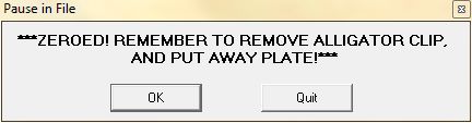
Once the machine is set with the z+-axis we havr to keep back the aluminum plate and aligator clip Then set the machine spindle speed and flow
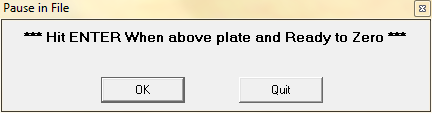
Setting up the z-axis
I have selected the 6mm Upcut bit and selected speed of spindle as 12000RPM, Feed rate of 45mm/sec and plung rate of 25mm/sec.and similarly for the engraving i have used the v-bit
Test Cut
This is made to understand on which value and how much engraving depth will be required for my assignment material and also for becoming familier to handle the machine control software and the setup of the job
Setting up the test job in the Vcarve 3D viewer for the engraving
Setting up the test job in the Vcarve 3D viewer
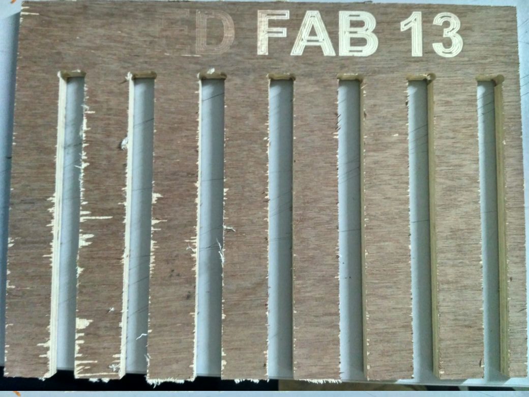
This the test cut (12mm plywood)on the existing tables tolerance
from this i have figured out the 16.5mm is the tolerance for trhe matrial which i am building the projector stand using the 12mm plywood,now we can cut the final design by following the basic rules
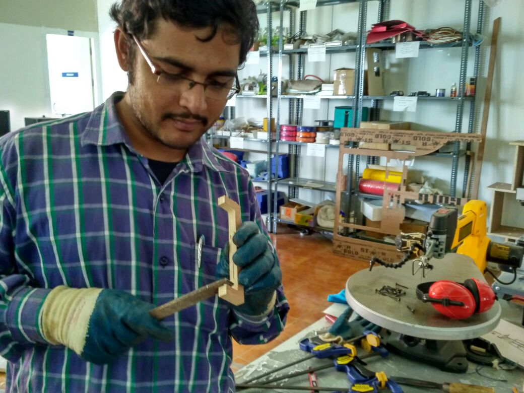
Group Test Cut
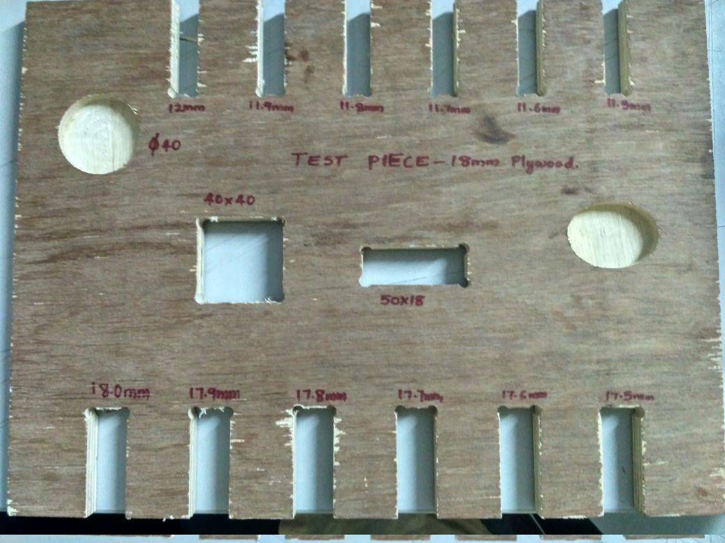
This is the test part we made inorder to find out the tolerance parameters for the pressfit. Designed it on rhino with different dimensions for 18mm and 12 mm plywood sheets like the one shown below. This was done in 18mm plywood sheet and tested pockets, rectangular cuts etc to check the parameters. The piece was cut on shopbot with 6mm upcut bit and checked the tolerance and found that for 18mm plywood 0.5mm is good for pressfits and for 12 mm plywood 0.4mm tolerance is good.
This the test cut (12mm plywood)on the first day of the assignment
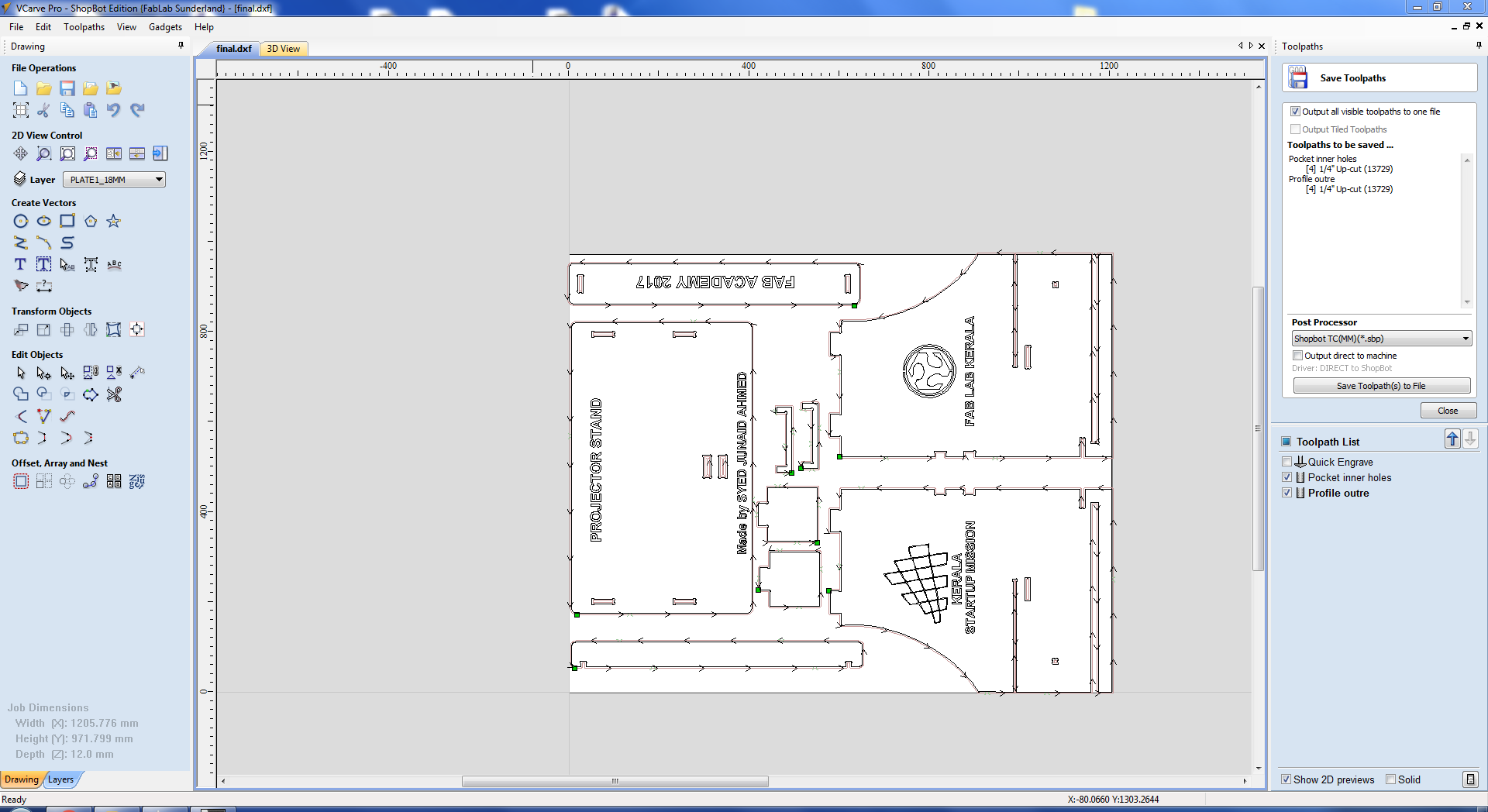
Setting up the job in the Vcarve 2D viewer
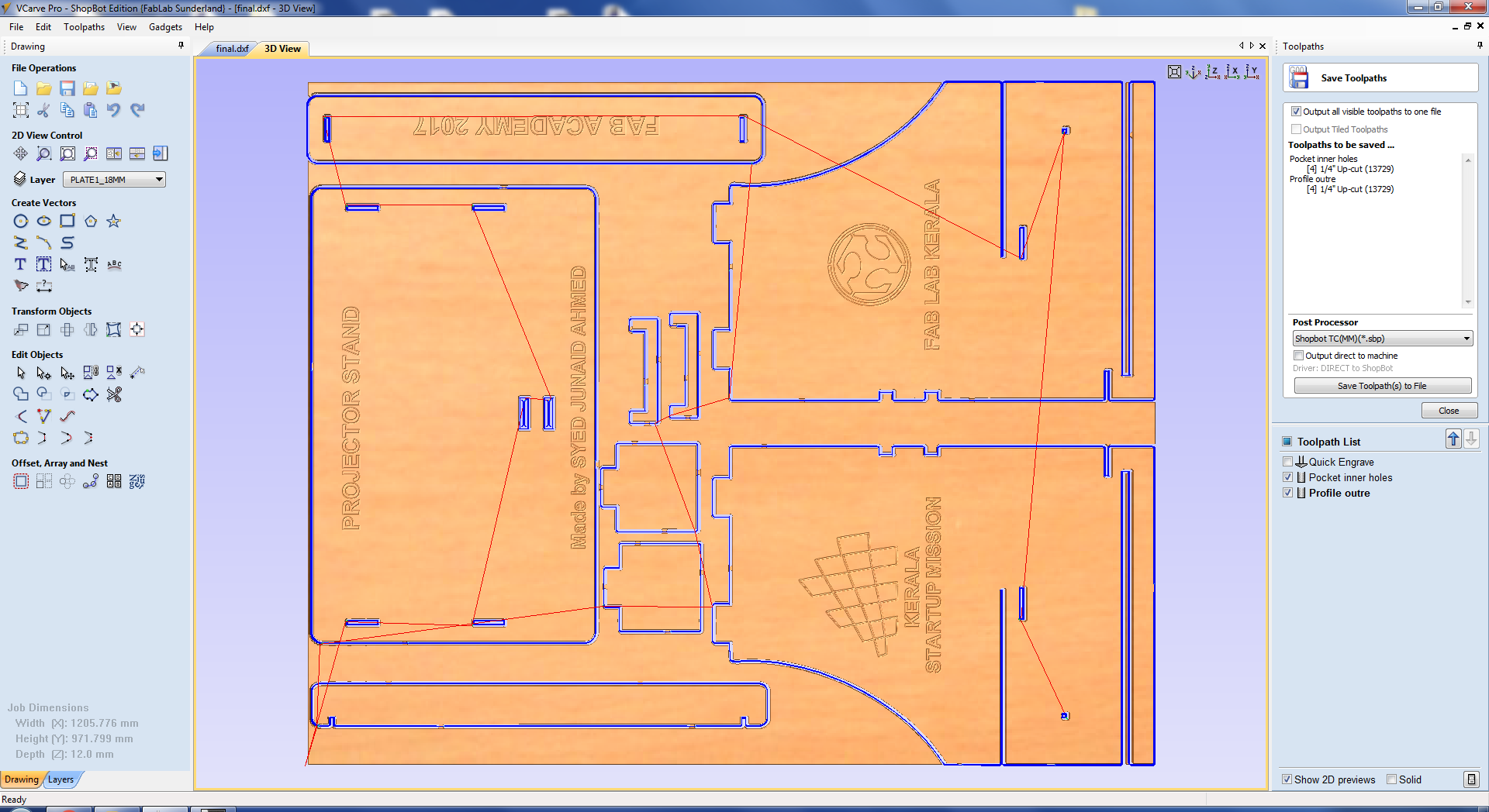
Setting up the job in the Vcarve 3D viewer
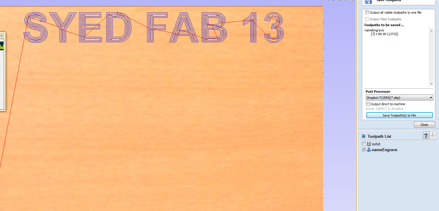
Now Finally we have completed all the settings we will send the engraving path with the v-bit as shown bleow we have to select the cut path and choose the .sbp required to engrave
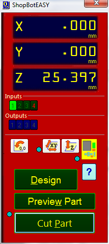
Select the cut part from the shopbot controller
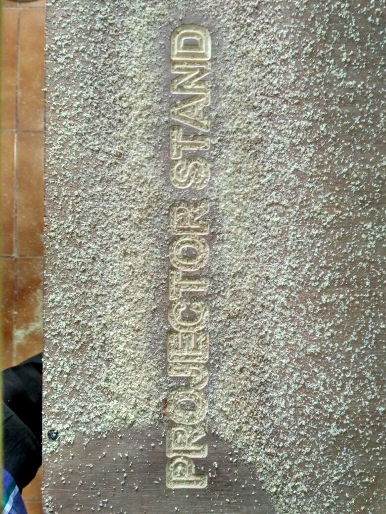
Engraving started
Once the Engraving is done we should change the bit to the 6mm upcut bit and now you have to select the cut part and start the cutting
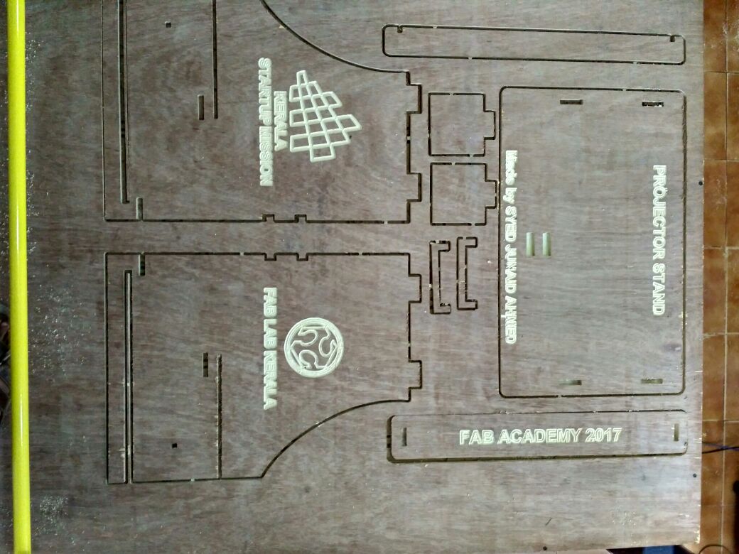
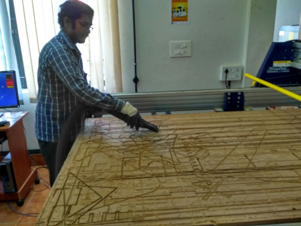
Finally whole job is compeletd
Finally we can see the post processing and the essembled final product in the slider below
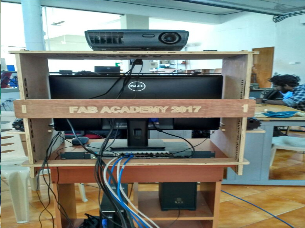
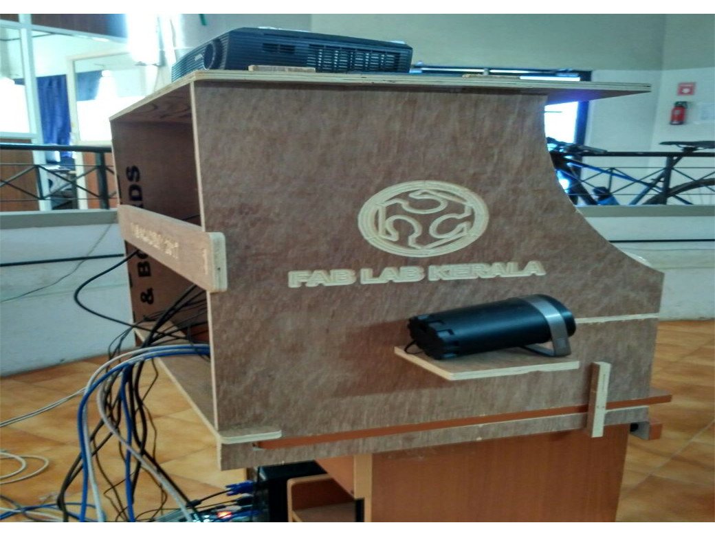
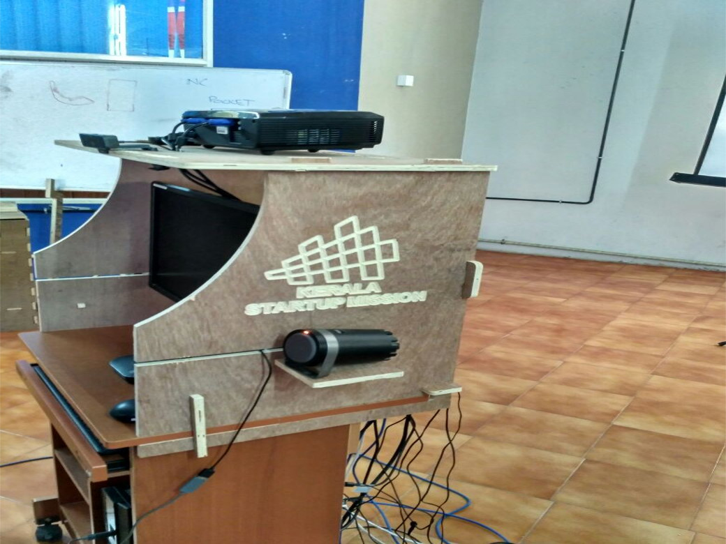
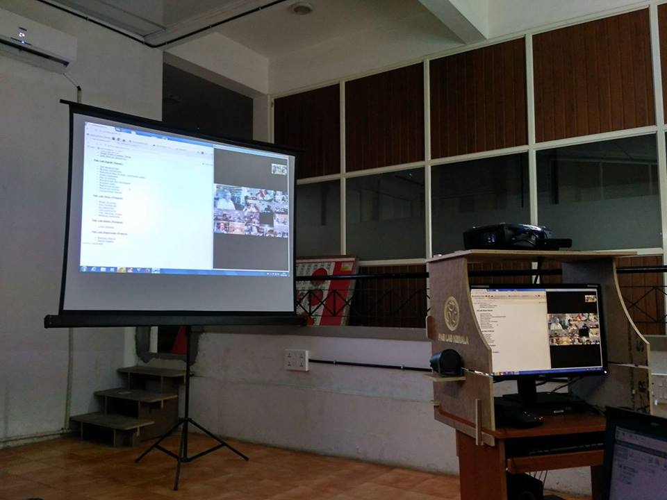
Hero Shot
Now here we comes to the Hero Shot of the Something Big Made this Week
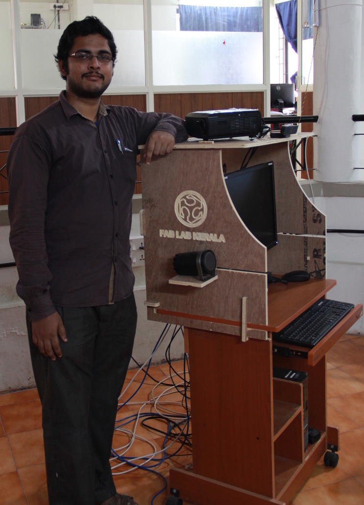
Finally my CNC Machining Week Completed
