Write an application that interfaces with an input and/or output device that you made, comparing as many tool options as possible.
*Interpret and implement design and programming protocols to create a Graphic User Interface (GUI).
*Described your process using words/images/screenshots.
*Explained the the GUI that you made and how you did it.
*Outlined problems and how you fixed them.
*Included original code.
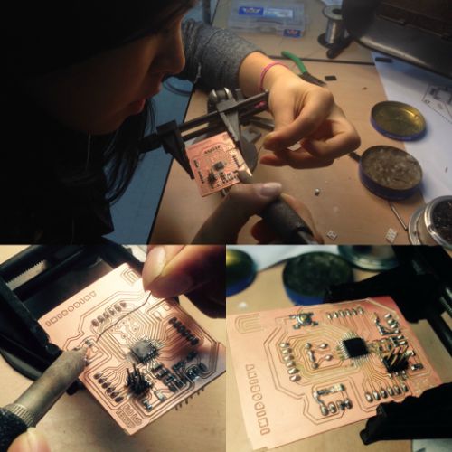
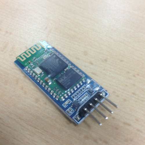
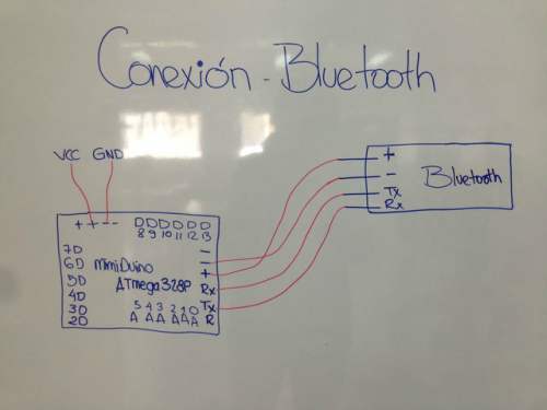
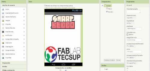
For this activity, I developed an application to control my project. For this purpose, I made my own fabduino card, which I called "mimiduino", to which the relays are connected, and to these last ones, the 4 solenoid valves / valves that control the movement of the modules of my project. So, for this I chose APP Inventor. Here I will explain my procedure step by step.
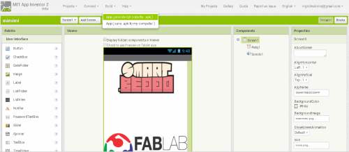
1. First I signed in with the email account. I chose to create a new project and I started.
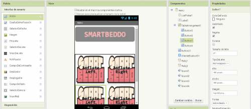
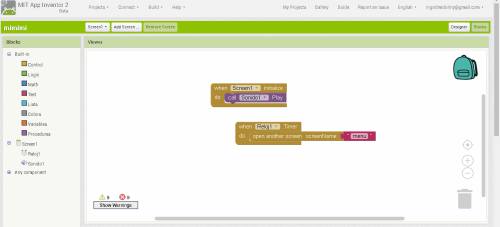
2. I worked two screens. The first "menu" included an audio file that I recorded welcoming the application of my project "Welcome to Smartbeddo", I set a time of 5 seconds so that later the second screen appears.
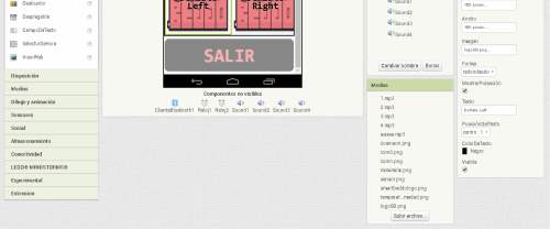
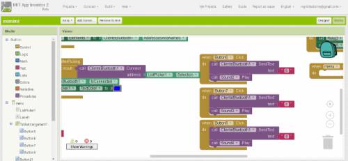
3. On the second screen you will find 6 buttons. The first one has the text: "Smartbeddo", so when they click there they will be able to choose the USB device that has "mimiduino" connected. The other four, which I arranged using Table Arrangement, are those that are directly oriented to send the signals "a", "b", "c" and "d"; which in the programming are respectively ordered to fulfill the functions of inflate and deflate the right or left. Each one of them has an image and an audio indicating that movement is being done, for example, "to move to the right". Finally the last button is to "Exit" and close the application. I made all these steps with blocks (Built-in, menu, TableArrangement), they depend of what you want to order. Color blocks on APP Inventor are very helpful.
To better understand how I made my interface application, I will explain you here :
First I made the own version of Fabduino, called "Mimiduino"
You can find the files on the Electronics desing part of my final project documentation
And here I have a bluetooth to control all my final project with the cellphone
Trough this picture I will show you how to make the connection
Then you have to open APP INVENTOR
MIT App inventor was the platform I choose to do my application on, as it uses Blockly environment, and it has an easy drag and drop Graphical interface.
Make 2 screens in this case:
Start to drag and drop the blocks, according what do you wwant to do
At the begining, I explained to you in detail what criteria are considered for my programming.
And then you have to generate QR code of the file, to download in your android cellphone
As you can see ypu will have at your cellphone and you will be able to control Smartbeddo.
Trough this video you can see how it works. This was the first time, and the beginnig of my dream to help a lot of people, and to achieve the promise that I made to uncle Tamo, Naomi and Marcelino. R.I.P my angels!
int IO = 2;
int IC = 3;
int DO = 4;
int DC = 5;
void setup() {
Serial.begin(9600);
pinMode(IO, OUTPUT);
pinMode(IC, OUTPUT);
pinMode(DO, OUTPUT);
pinMode(DC, OUTPUT);
}
void loop() {
if (Serial.available() > 0) {
int inByte = Serial.read() ;
switch (inByte) {
case 'a':
digitalWrite(IO,LOW);
digitalWrite(IC,HIGH);
delay(10000);
digitalWrite(IO,HIGH);
digitalWrite(IC,HIGH);
break;
case 'b':
digitalWrite(DO,LOW);
digitalWrite(DC,HIGH);
delay(10000);
digitalWrite(DO,HIGH);
digitalWrite(DC,HIGH);
break;
case 'c':
digitalWrite(IO,HIGH);
digitalWrite(IC,LOW);
break;
case 'd':
digitalWrite(DO,HIGH);
digitalWrite(DC,LOW);
break;
}
}
}
This way I have managed to control my project from the cellphone, considering four outputs to my solenoid valves. I tried something new for me, as making an app.
APP Inventor it's a really interesting and dynamic software for doing it, now I can read block language and make a good design, I think it is easy by using it.