


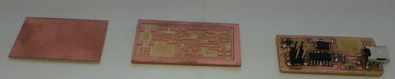
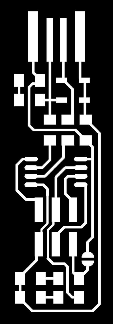
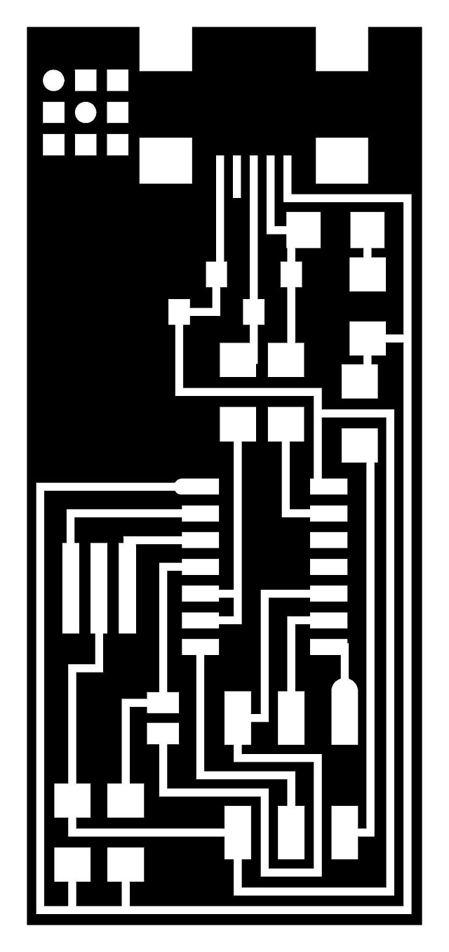
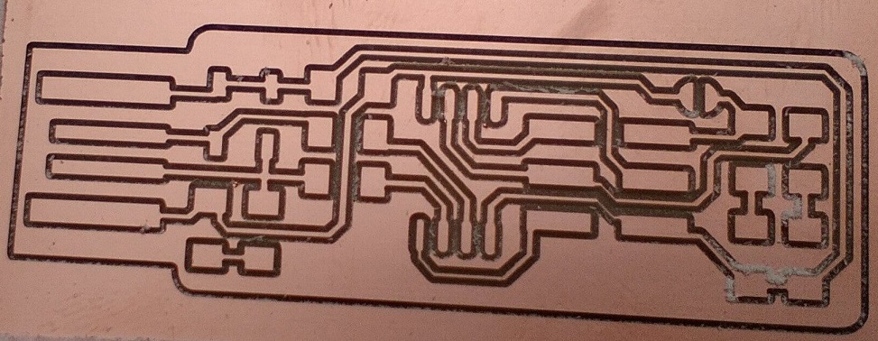
- Download and mill the electronic boards.
- Weld the electronic components on the boards.
- Configure an electronic board.
- Program the ATtiny45.
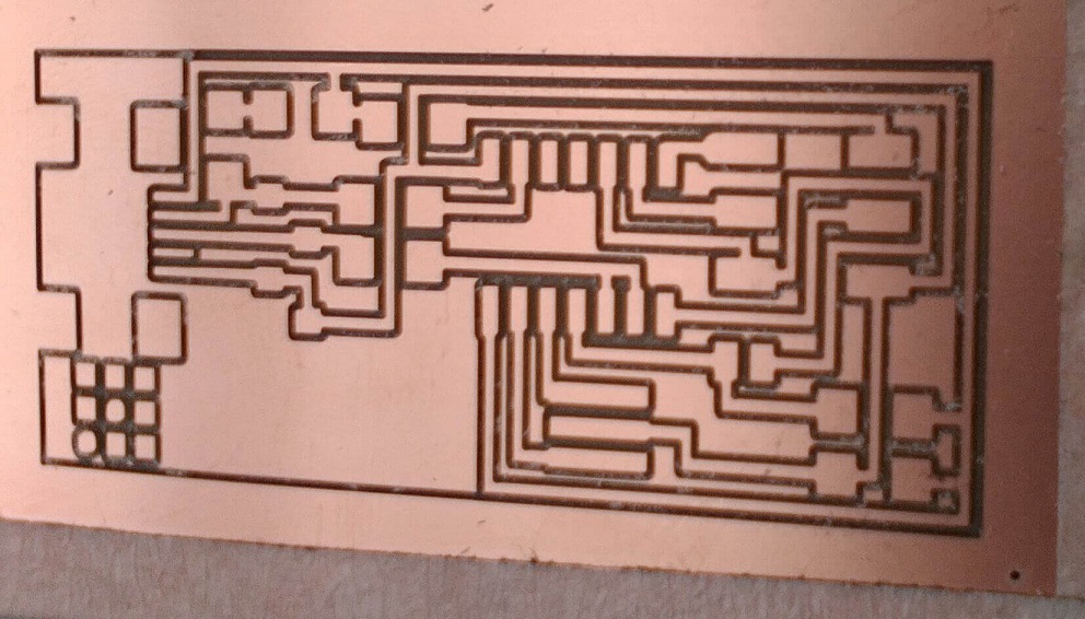
1. Download the png files for paths and the schematics of the electronic boards.
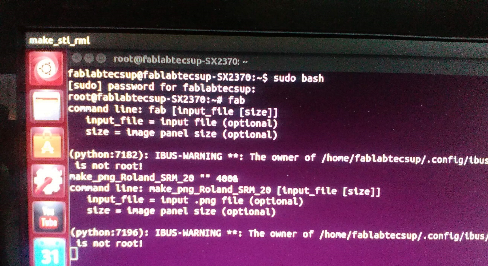
2. Go to the terminal
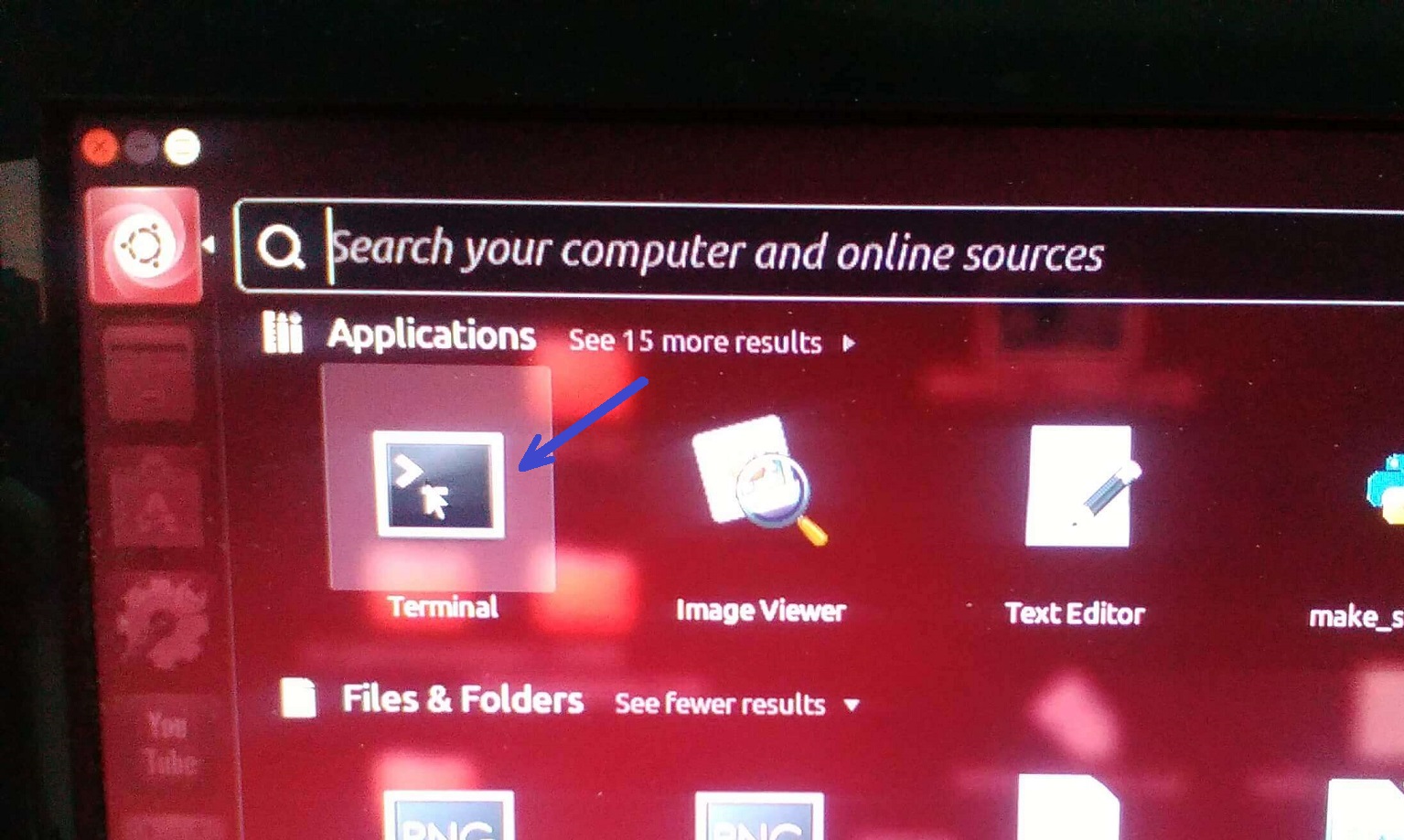
3. In the terminal use the command sudo bash
4. Use the command fab.
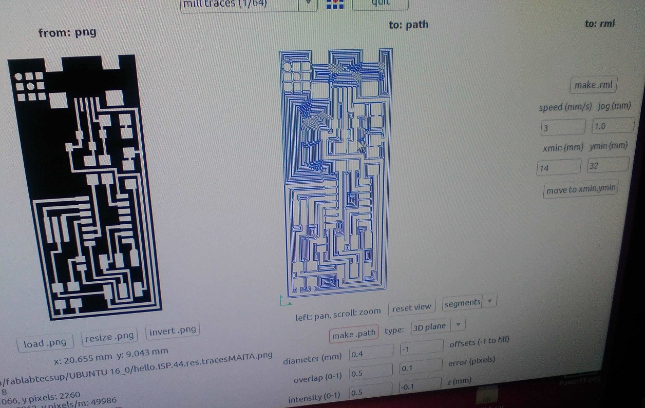
5. Now select the image
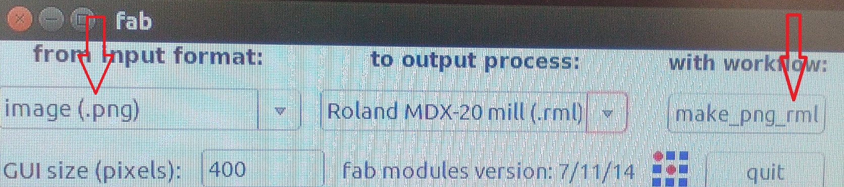
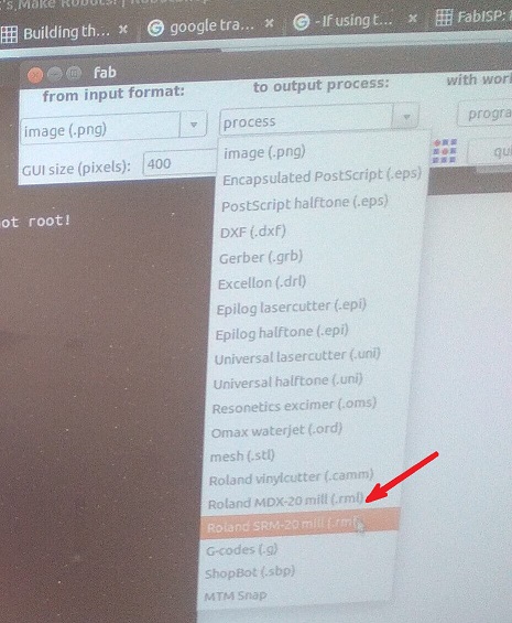
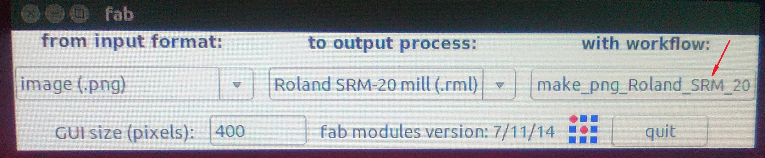
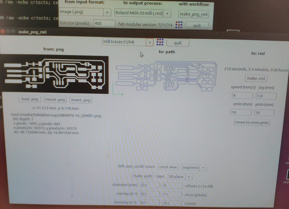
6. Now choose the machine: Roland Modela MDX - 20
7. Now click on make_png_rml
8. On defaults you have to select the milling tool you will use. It usually is 1/64" (0.4mm). After that select the file to load, clicking load.png.
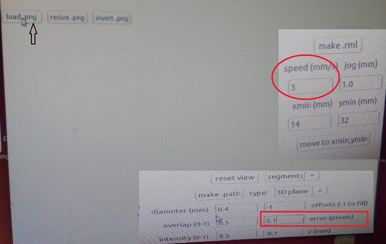
9. It will show a window where you have to click on make.path and configure the parameters or the milling. (Every time you modify a parameter you need to click on make path)
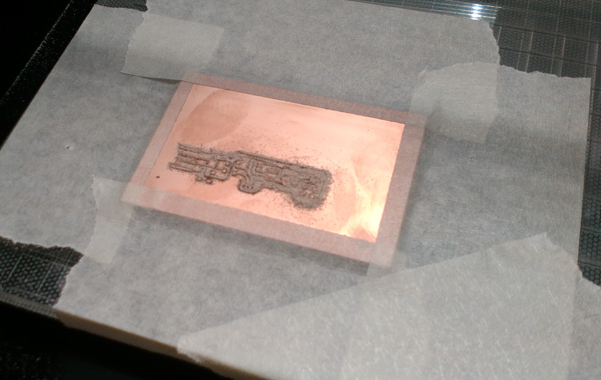
10. Place the board on the Modela. Fix it to the base.
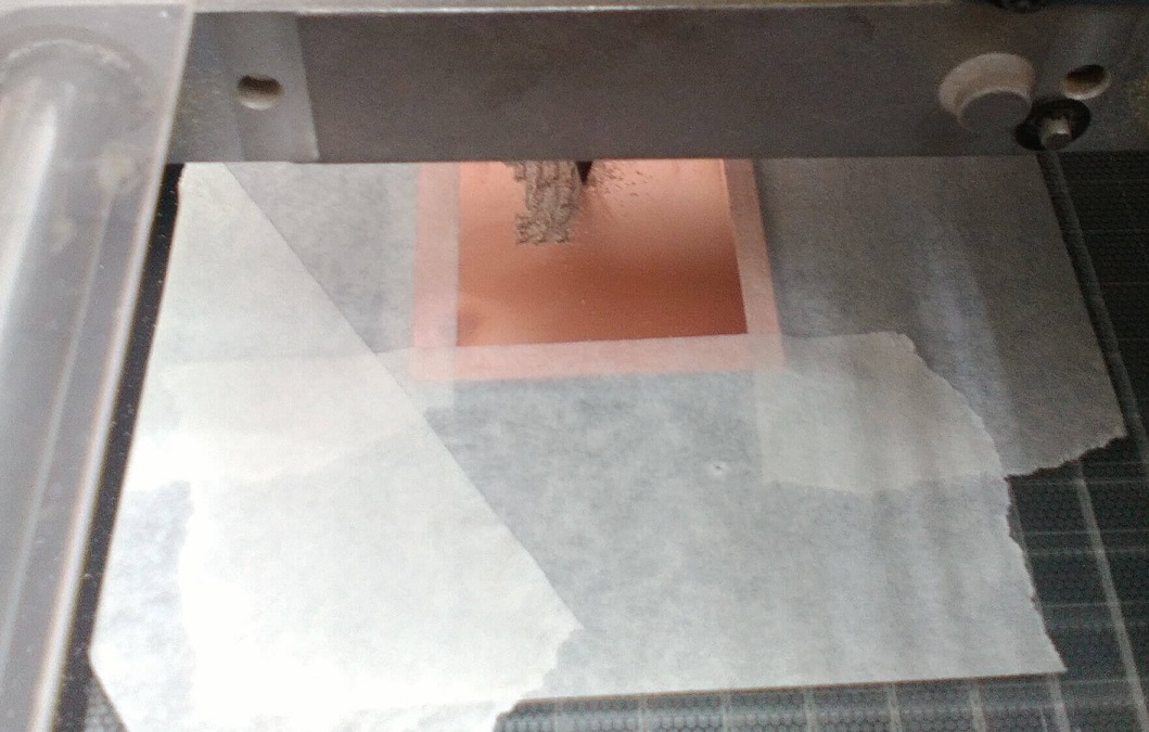
Calibrate the x and y points.
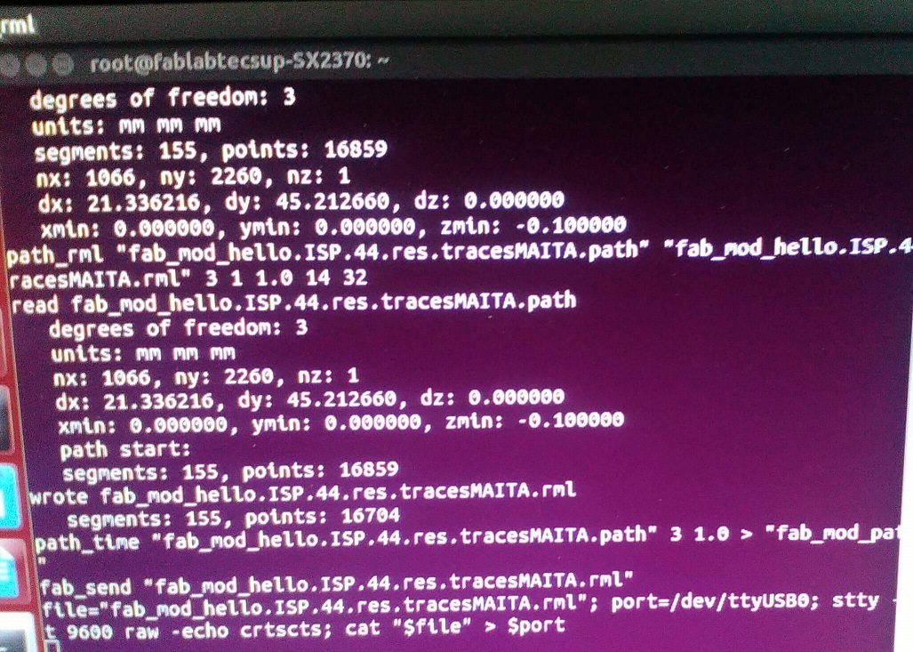
Calibrate the z axis manually, using the Up and Down buttons. Finally click no make.rml and Send it
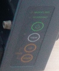
Important: Do not remove the plastic guard from the machine. It has a metalic piece detected by a sensor on the machine. If you remove it the machine wont move.
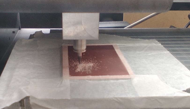
The milling tools allows you to mechanize metal like cooper, from 0.09 to 6 mm in depth. We use Altin coated micrograin.
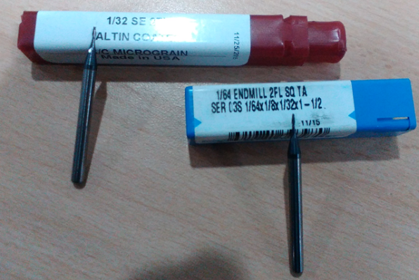
Too much depth cut and milling tool broke
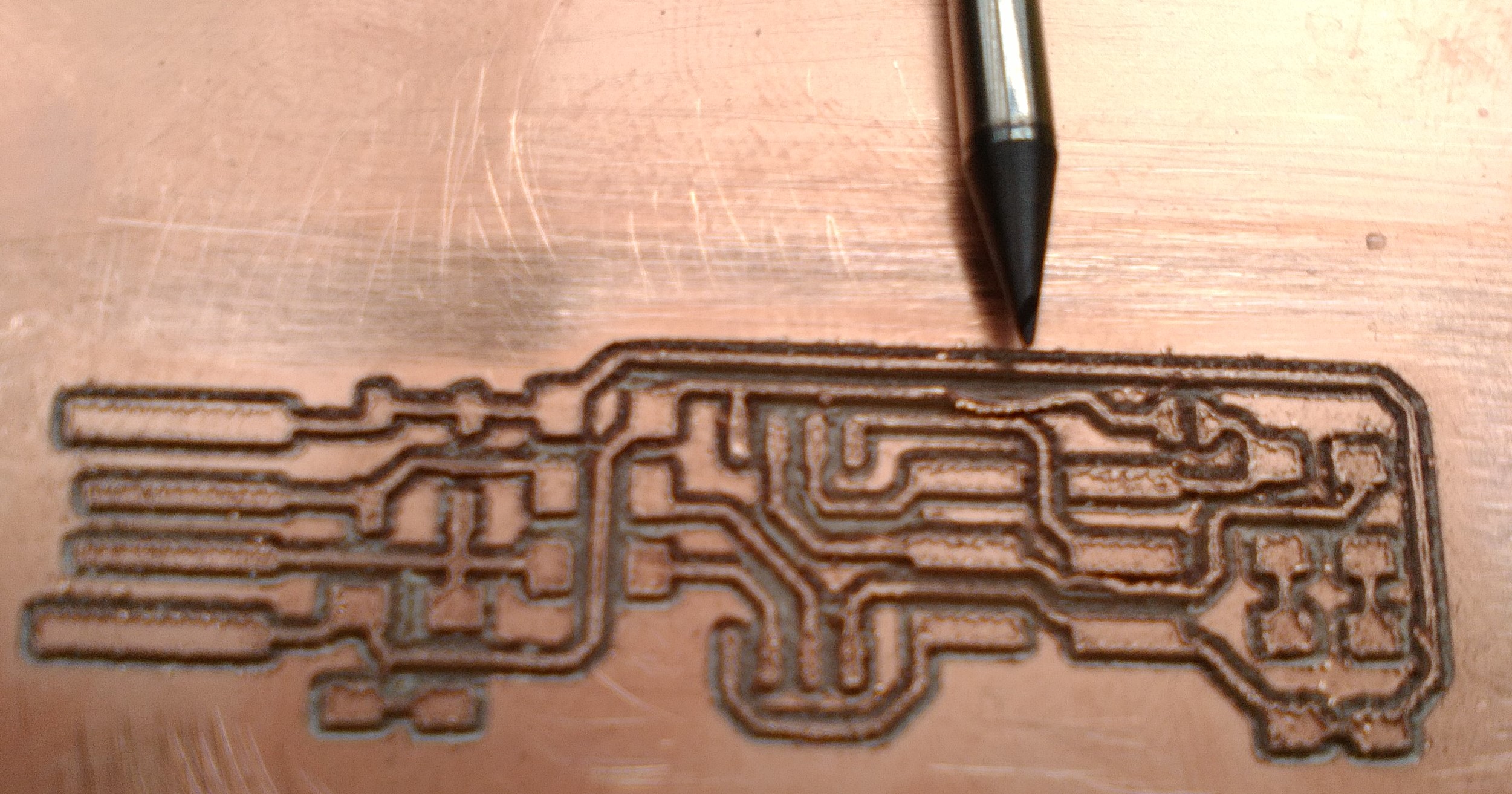
The right cut depth is 0.1mm. Configure it that way
You need the board components:
1x ATtiny45 or ATtiny85
2x 1kΩ resistors
2x 499Ω resistors
2x 49Ω resistors
2x 3.3v zener diodes
1x red LED
1x green LED
1x 100nF capacitor
1x 2x3 pin header
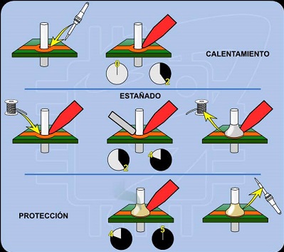
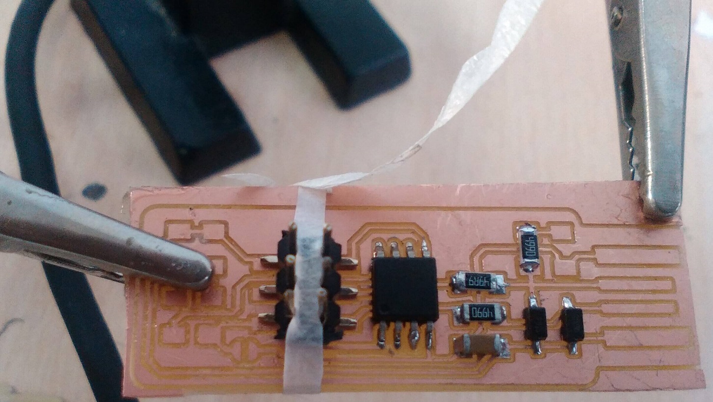
Here we use a soldier property: Capilarity. It occurs when two componets are close to each other. When you melt the tin on one of them, the other one also gets covered.
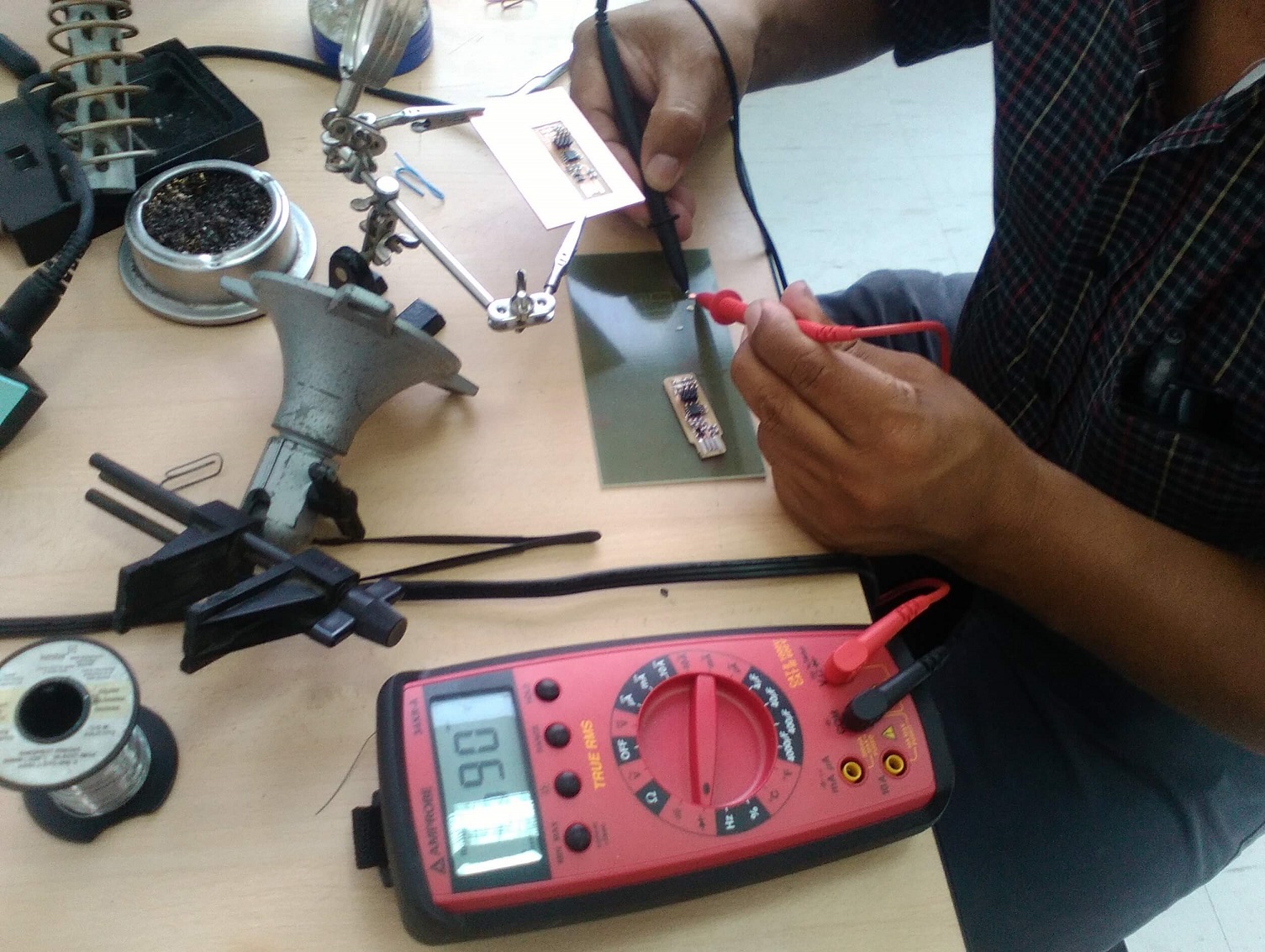
Doing the continuity test
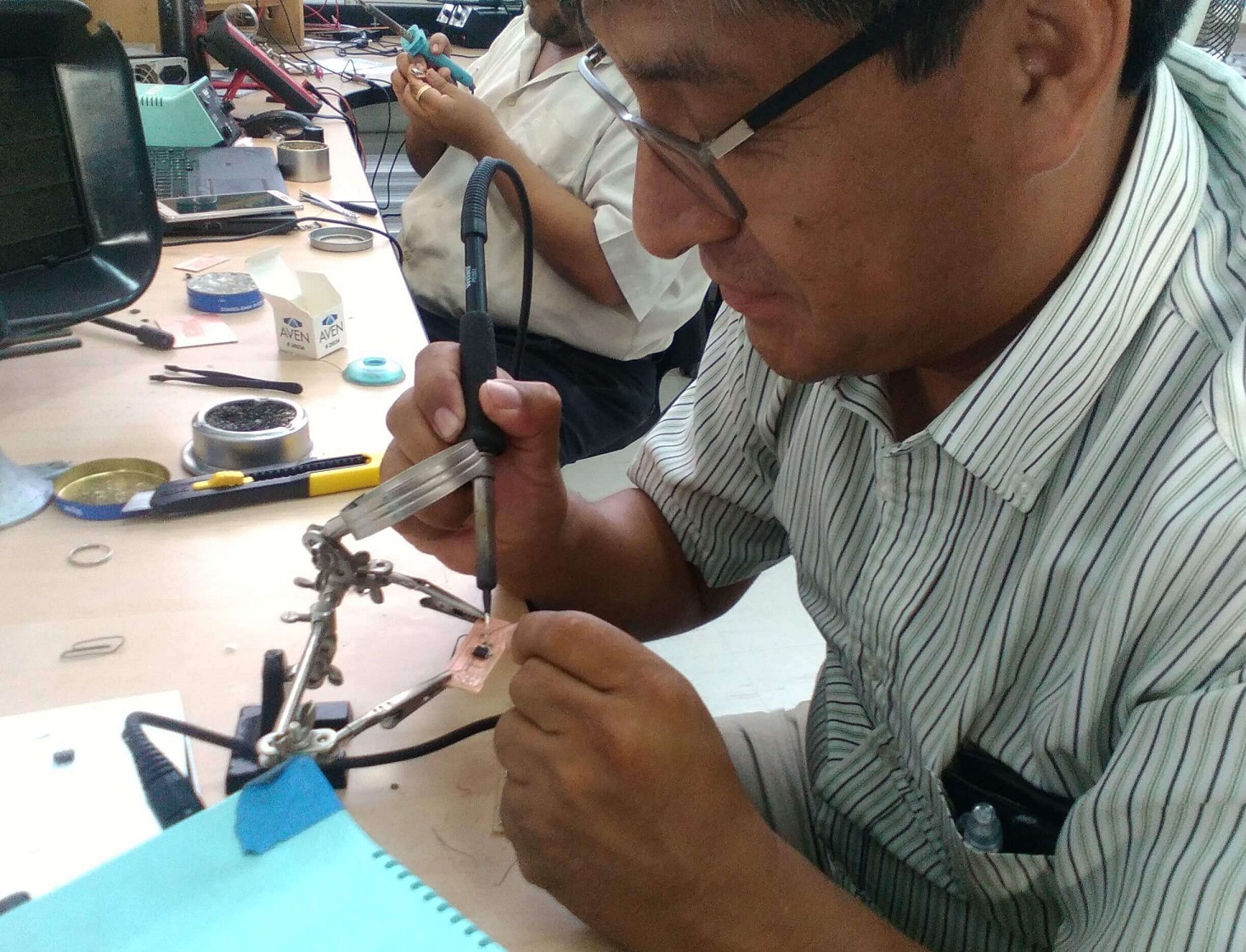
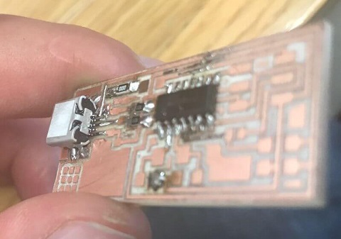
Trying to hold the component
Finished board
1. Heat the elements to solder.
2. Apply tin
3. Keep the joint hot until tin spreads
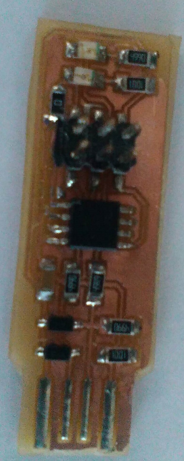
Verify the soldering and the components position
Equipment: Laptop
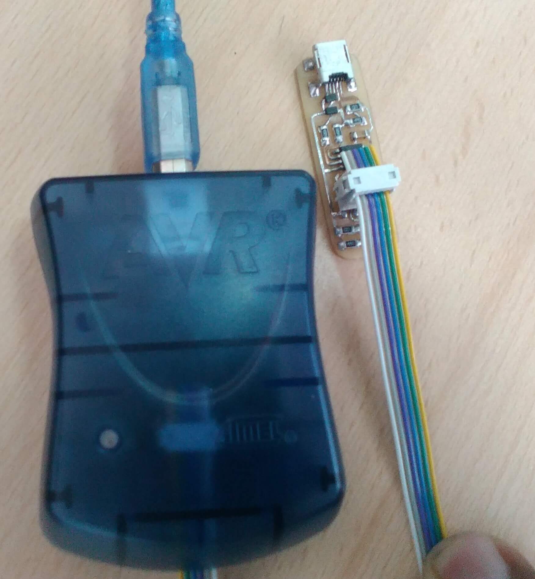
Equipment: AVR - ATMEL
Software: Terminal.
- Verify the components position and the right welding of the electronic board.
- Program the board using the AVR
1. Open the terminal and use the next command
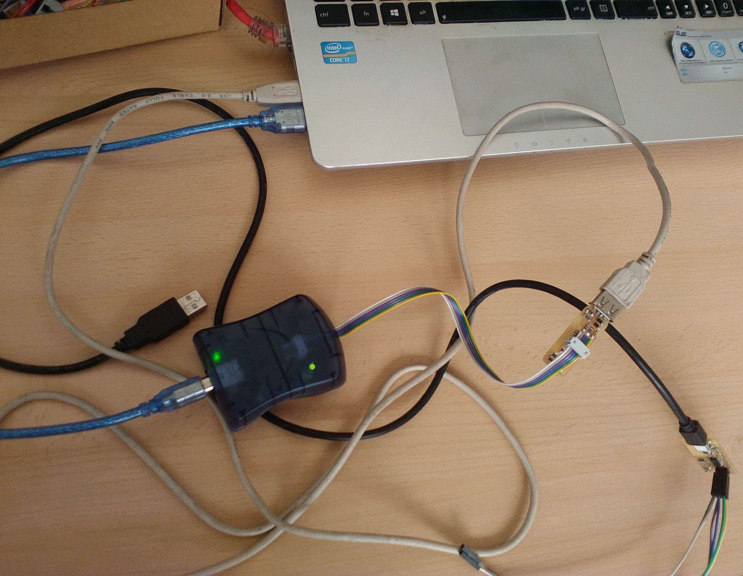
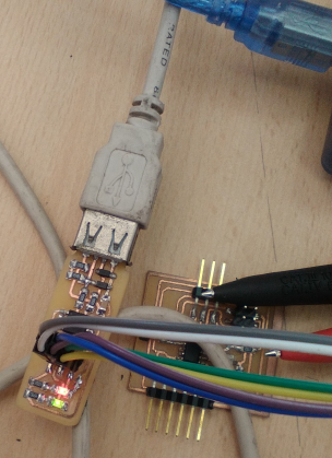
2 Make the AVR - board connections.
Installation for the corresponding burn
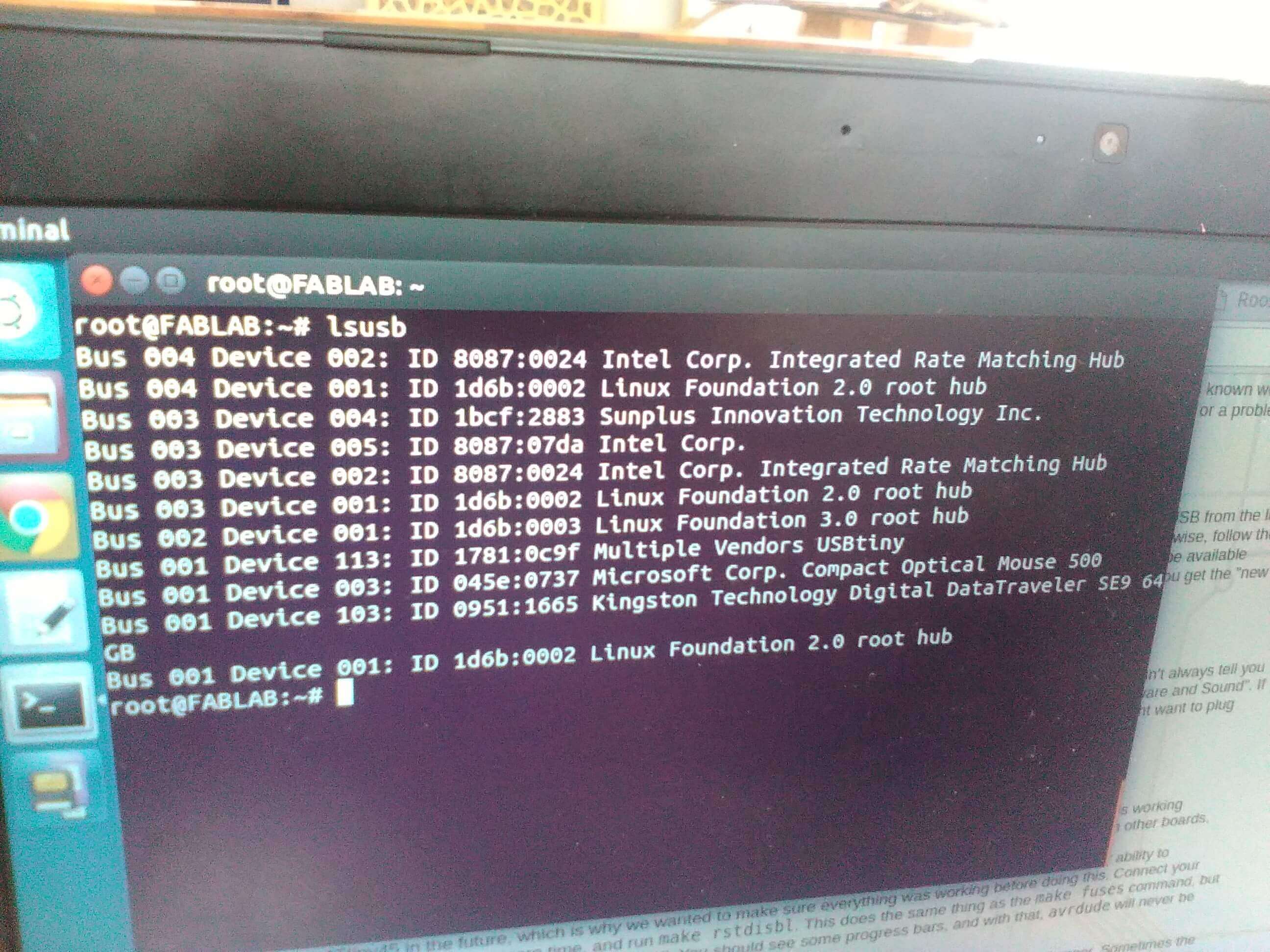
root@FABLAB:~/Escritorio/fab# lsusb
Bus 004 Device 002: ID 8087:0024 Intel Corp. Integrated Rate Matching Hub
Bus 004 Device 001: ID 1d6b:0002 Linux Foundation 2.0 root hub
Bus 003 Device 004: ID 1bcf:2883 Sunplus Innovation Technology Inc.
Bus 003 Device 005: ID 8087:07da Intel Corp.
Bus 003 Device 002: ID 8087:0024 Intel Corp. Integrated Rate Matching Hub
Bus 003 Device 001: ID 1d6b:0002 Linux Foundation 2.0 root hub
Bus 002 Device 001: ID 1d6b:0003 Linux Foundation 3.0 root hub
Bus 001 Device 116: ID 045e:0737 Microsoft Corp. Compact Optical Mouse 500
Bus 001 Device 059: ID 1781:0c9f Multiple Vendors USBtiny
Bus 001 Device 001: ID 1d6b:0002 Linux Foundation 2.0 root hub
root@FABLAB:~/Escritorio/fab# make flash
avr-gcc -mmcu=attiny45 -Wall -DF_CPU=16500000UL -I. -funsigned-char -funsigned-bitfields
-fpack-struct -fshort-enums -Os -Iusbdrv -c main.c -o main.o
main.c:109:13: warning: always_inline function might not be inlinable [-Wattributes]
static void delay ( void )
^
avr-gcc -mmcu=attiny45 -Wall -DF_CPU=16500000UL -I. -funsigned-char -funsigned-bitfields
-fpack-struct -fshort-enums -Os -Iusbdrv -c usbdrv/usbdrv.c -o usbdrv/usbdrv.o
avr-gcc -mmcu=attiny45 -Wall -DF_CPU=16500000UL -I. -funsigned-char -funsigned-bitfields
-fpack-struct -fshort-enums -Os -Iusbdrv -c usbdrv/oddebug.c -o usbdrv/oddebug.o
avr-gcc -x assembler-with-cpp -mmcu=attiny45 -Wall -DF_CPU=16500000UL -I. -funsigned-char
-funsigned-bitfields -fpack-struct -fshort-enums -Os -Iusbdrv -c usbdrv/usbdrvasm.S -o
usbdrv/usbdrvasm.o avr-gcc -mmcu=attiny45 -o fts_firmware.elf main.o usbdrv/usbdrv.o
usbdrv/oddebug.o usbdrv/usbdrvasm.o avr-size -C --mcu=attiny45 fts_firmware.elf
AVR Memory Usage
----------------
Device: attiny45
Program: 2488 bytes (60.7% Full)
(.text + .data + .bootloader)
Data: 75 bytes (29.3% Full)
(.data + .bss + .noinit)
avr-objcopy -j .text -j .data -O ihex fts_firmware.elf fts_firmware.hex
avrdude -p attiny45 -c usbtiny -P usb -e \
-U flash:w:fts_firmware.hex
avrdude: initialization failed, rc=-1
Double check connections and try again, or use -F to override
this check.
avrdude done. Thank you.
root@FABLAB:~/Escritorio/fab# make flash
avrdude -p attiny45 -c usbtiny -P usb -e \
-U flash:w:fts_firmware.hex
avrdude: AVR device initialized and ready to accept instructions
Reading | ################################################## | 100% 0.00s
avrdude: Device signature = 0x1e9206
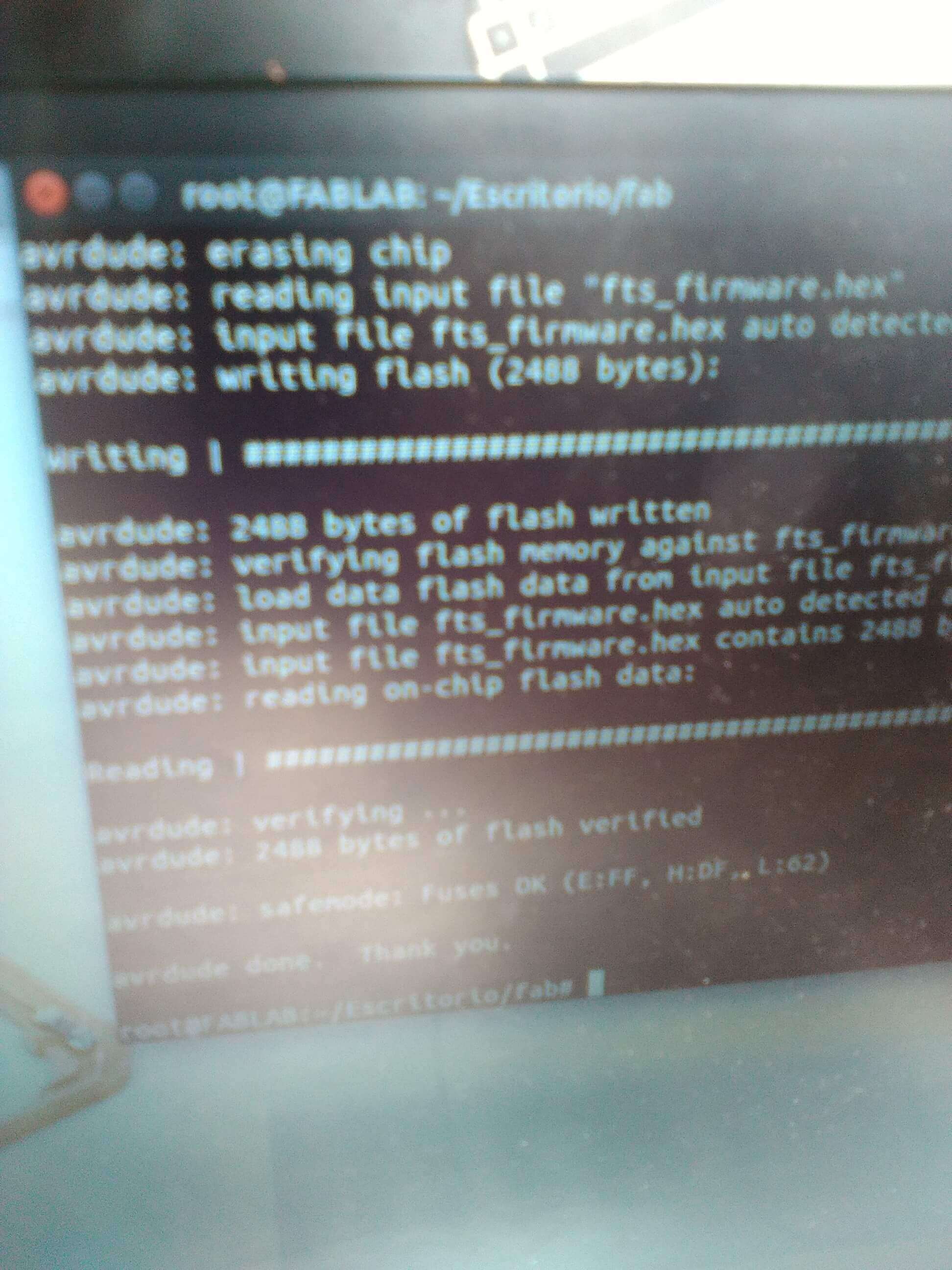
avrdude: erasing chip
avrdude: reading input file "fts_firmware.hex"
avrdude: input file fts_firmware.hex auto detected as Intel Hex
avrdude: writing flash (2488 bytes):
Writing | ################################################## | 100% 2.43s
avrdude: 2488 bytes of flash written
avrdude: verifying flash memory against fts_firmware.hex:
avrdude: load data flash data from input file fts_firmware.hex:
avrdude: input file fts_firmware.hex auto detected as Intel Hex
avrdude: input file fts_firmware.hex contains 2488 bytes
avrdude: reading on-chip flash data:
Reading | ################################################## | 100% 2.89s
avrdude: verifying ...
avrdude: 2488 bytes of flash verified
avrdude: safemode: Fuses OK (E:FF, H:DF, L:62)
avrdude done. Thank you.
root@FABLAB:~/Escritorio/fab# make fuses
avrdude -p attiny45 -c usbtiny -P usb \
-U lfuse:w:0xE1:m -U hfuse:w:0xDD:m \
-U efuse:w:0xFF:m
avrdude: AVR device initialized and ready to accept instructions
Reading | ################################################## | 100% 0.00s
avrdude: Device signature = 0x1e9206
avrdude: reading input file "0xE1"
avrdude: writing lfuse (1 bytes):
Writing | ################################################## | 100% 0.01s
avrdude: 1 bytes of lfuse written
avrdude: verifying lfuse memory against 0xE1:
avrdude: load data lfuse data from input file 0xE1:
avrdude: input file 0xE1 contains 1 bytes
avrdude: reading on-chip lfuse data:
Reading | ################################################## | 100% 0.00s
avrdude: verifying ...
avrdude: 1 bytes of lfuse verified
avrdude: reading input file "0xDD"
avrdude: writing hfuse (1 bytes):
Writing | ################################################## | 100% 0.01s
avrdude: 1 bytes of hfuse written
avrdude: verifying hfuse memory against 0xDD:
avrdude: load data hfuse data from input file 0xDD:
avrdude: input file 0xDD contains 1 bytes
avrdude: reading on-chip hfuse data:
Reading | ################################################## | 100% 0.00s
avrdude: verifying ...
avrdude: 1 bytes of hfuse verified
avrdude: reading input file "0xFF"
avrdude: writing efuse (1 bytes):
Writing | ################################################## | 100% 0.00s
avrdude: 1 bytes of efuse written
avrdude: verifying efuse memory against 0xFF:
avrdude: load data efuse data from input file 0xFF:
avrdude: input file 0xFF contains 1 bytes
avrdude: reading on-chip efuse data:
Reading | ################################################## | 100% 0.00s
avrdude: verifying ...
avrdude: 1 bytes of efuse verified
avrdude: safemode: Fuses OK (E:FF, H:DD, L:E1)
avrdude done. Thank you.
Verify the right position of electronic components befor soldering
Program the Fab Isp