Project development
What tasks have been completed, and what tasks remain?
All the tasks planned for the 1st version of final project have been completed. what remains are enhacements and the next version to address some of the minor issue face.
What has worked? what hasn't?
The final project meets minimum expectation. what hasn't worked really well is 3D printing quality for gear trains tolerance. But this is a minor issue, the robot arm still works.
what questions need to be resolved?
No major questions need to be resolved.
What will happen when?
The next version of robotic arm is under way, you can see it in progress at the end of this page.
What have you learned?
Fab Academy skills are quite comprehensive and relevent to making projects. I think the most significant take away is getting know a community of like minded people along the way.
This page records the events leading to the completion of final project. It does not describe the final project in detial.
For final project page, click the Final Project Icon ->
The journey of making it
Research
Week 1
Robot anatomy
Type of robots
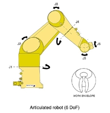
Articulated robot – is the most versatile type and closely resembles
the kinematics of the human arm. It has three concurrent prismatic or rotary joints, with a
further 3 axes in the wrist, giving 6 DoF. Its end effector can be manipulated to any
orientation in the work envelope, which is almost spherical. The capacity to reach over and
around constructions and twist or tilt the end effector, make it ideal for complex part
removal/installation, processing, arc and spot welding, paint spraying, mould unloading and
machine tending tasks.
Benefits Drawbacks
Large work envelope More expensive
Small footprint More components
Highly flexible Complex algorithms
Fast operating speed Less rigid at full reach
Type of robots
Articulated robot – is the most versatile type and closely resembles
the kinematics of the human arm. It has three concurrent prismatic or rotary joints, with a
further 3 axes in the wrist, giving 6 DoF. Its end effector can be manipulated to any
orientation in the work envelope, which is almost spherical. The capacity to reach over and
around constructions and twist or tilt the end effector, make it ideal for complex part
removal/installation, processing, arc and spot welding, paint spraying, mould unloading and
machine tending tasks.
Benefits Drawbacks
Large work envelope More expensive
Small footprint More components
Highly flexible Complex algorithms
Fast operating speed Less rigid at full reach
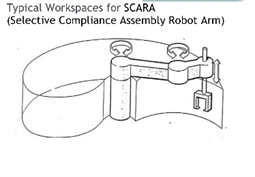
SCARA robot – selective compliance assembly robot arm, this has 4 DoF,
with two parallel rotational joints, a translational joint for vertical positioning, and a simple
rotating wrist. This has a quasi-cylindrical work envelope, referred to as cardioidal, but the
end effector is more restricted in orientation. It is commonly used for routine pick & place,
assembly, packaging, palletising and machine loading applications and has arguably the best
price/performance ratio.
Benefits Drawbacks
Good vertical stiffness Restricted motion
Fewer joints/components Less flexibility
Small footprint Horizontal compliance
High speed operation
Good payloads
Excellent repeatability
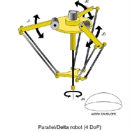
Delta Robot - also known as a high speed
picker; it looks less like a conventional robot and more like a three- or four-legged spider,
with a fourth moving element extending from the centre to manipulate the end effector, within
a hemispherical work envelope. It has 4 DoF, three translational and one rotational, and
because the actuators are mounted off the lightweight arms on the overhead chassis, there
is less mass to accelerate and very high speeds are possible (up to 150 picks per minute
compared to 60-65 ppm for a SCARA). Its key applications are picking and packaging lighter
payloads in the food, pharmaceuticals, plastics and life sciences industries.
Benefits Drawbacks
Very high speeds Smaller payloads
Low installation profile Less flexibility
Low gross weight Restricted workspace
Long term reliability Complex algorithms
Conceptual mechanical design
Week 2
Motor selection
Drive system
Type of motors
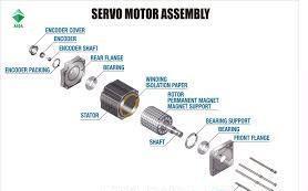
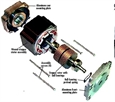
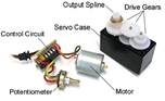
Servo Motors
Fast, high torque, accurate rotation within a limited angle – Generally a high performance alternative to stepper motors, but more complicated setup with PWM tuning. Suited for robotic arms/legs or rudder control etc.
Stepper Motors
Slow, precise rotation, easy set up & control – Advantage over servo motors in positional control. Where servos require a feedback mechanism and support circuitry to drive positioning, a stepper motor has positional control via its nature of rotation by fractional increments. Suited for 3D printers and similar devices where position is fundamental.
RC servo motor
Small cheap, also known as remote control servo motor, it is mainly used in hobyist remote control air plane and toys.
Type of motors
Servo Motors
Fast, high torque, accurate rotation within a limited angle – Generally a high performance alternative to stepper motors, but more complicated setup with PWM tuning. Suited for robotic arms/legs or rudder control etc.
Stepper Motors
Slow, precise rotation, easy set up & control – Advantage over servo motors in positional control. Where servos require a feedback mechanism and support circuitry to drive positioning, a stepper motor has positional control via its nature of rotation by fractional increments. Suited for 3D printers and similar devices where position is fundamental.
RC servo motor
Small cheap, also known as remote control servo motor, it is mainly used in hobyist remote control air plane and toys.
Week 3
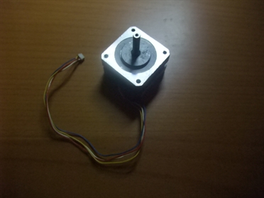
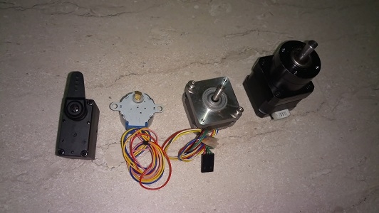
This week I have started working on the purchased components required. Mainly the drive motors.
In the picture below from a left:
1. RC servo motor,
2. 28BYJ stepper motor with gear reducer
3. Nema 18 2 phase stepper motor
4. Nema 18 2 phase stepper motor with gear reducer
I need to know these compoents size and mounting method to start working on the detial mechanical design. Information is available on the data sheets of the components.
Robot Kinematics
Week 4
Took a break, had a kitkat and went on a very short vacation:)
Week 5
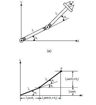
Robot arm kinematics
The kinematic models of robots describe how the motion of the joints of a robot is related to the motion of the rigid bodies
that make up the robot. This is required in the control software that tell the robot arm what angles to turn its motors to get the gripper to any point in 3D space. This software resides in PC, not the robot controller. The robot controller basically receives Gcodes and acts on its accordingly.
Some articles describing robot kinematics are shown below.
KINEMATIC ANALYSIS FOR ROBOT ARM
http://www.emo.org.tr/ekler/4f226e3f94cd5bb_ek.pdf
Robot Dynamics and Control
http://www.cds.caltech.edu/~murray/books/MLS/pdf/mls94-manipdyn_v1_2.pdf
Robot kinematics
http://www.cs.rpi.edu/academics/courses/spring03/robotic/handouts/exercise1.pdf
SCARA Robot Kinematics
http://www.deltatau.com/Common/technotes/SCARA%20Robot%20Kinematics.pdf
After reading all these, I find that the useful bit of information (or the bit that I can understand) can be summarised in the picture below.
Took a break, had a kitkat and went on a very short vacation:)
Week 5
Robot arm kinematics
The kinematic models of robots describe how the motion of the joints of a robot is related to the motion of the rigid bodies
that make up the robot. This is required in the control software that tell the robot arm what angles to turn its motors to get the gripper to any point in 3D space. This software resides in PC, not the robot controller. The robot controller basically receives Gcodes and acts on its accordingly.
Some articles describing robot kinematics are shown below.
KINEMATIC ANALYSIS FOR ROBOT ARM
http://www.emo.org.tr/ekler/4f226e3f94cd5bb_ek.pdf
Robot Dynamics and Control
http://www.cds.caltech.edu/~murray/books/MLS/pdf/mls94-manipdyn_v1_2.pdf
Robot kinematics
http://www.cs.rpi.edu/academics/courses/spring03/robotic/handouts/exercise1.pdf
SCARA Robot Kinematics
http://www.deltatau.com/Common/technotes/SCARA%20Robot%20Kinematics.pdf
After reading all these, I find that the useful bit of information (or the bit that I can understand) can be summarised in the picture below.
Electronics Design
Week 6
Studying possible motor drivers design
There are 4 motor drivers that are readily available that I can use for this projects, see picture below from left to right:
1. ULN2003 driver IC. This is a darlington transistors circuits. This IC requires external switching control for different coil of the motor.
2. A4988 Stepper IC Stepper motor driver carrier IC. This is a small foot print IC, it requires direction and step signal to run.
3. L298 Dual H bridge motor driver IC. Similar to A4988, it required Direction and step signal to run.
4. L298P SMD H bridge motor IC, in the picture, it is built into a Arduino shield. It is identical to the previous L298 but in SMD package.
After consideration, I have decided to use the A4988 stepper driver module. Four of these modules will be mounted on DIY PCB and interface to a DIY microcontroller board.
Week 7
Studying possible robot arm controller design
There are a few options for controlling the robot arm:
1. Arduino Uno with motor shield
2. Arduino Mega with Ramps 1.4
3. Custom design microcontroller and Driver board
I will make a modified Atmega 328P microcontroller board based on Atmega328 fabkit.
Studying possible robot arm controller design
There are a few options for controlling the robot arm:
1. Arduino Uno with motor shield
2. Arduino Mega with Ramps 1.4
3. Custom design microcontroller and Driver board
I will make a modified Atmega 328P microcontroller board based on Atmega328 fabkit.
Detial deisgn and fabrication
Week 8
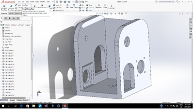
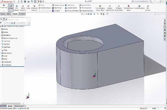
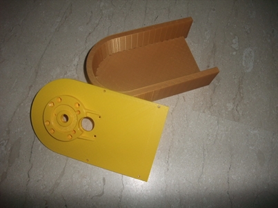
For this week, I have designed and made the base body and its top plate for the robotic arm. A stepper motor will be added later for robot arm's rotary movement.
For this week, I have designed and made the base body and its top plate for the robotic arm. A stepper motor will be added later for robot arm's rotary movement.
Week 9
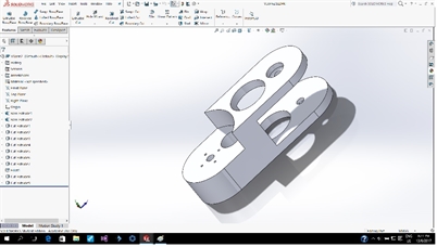
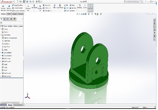
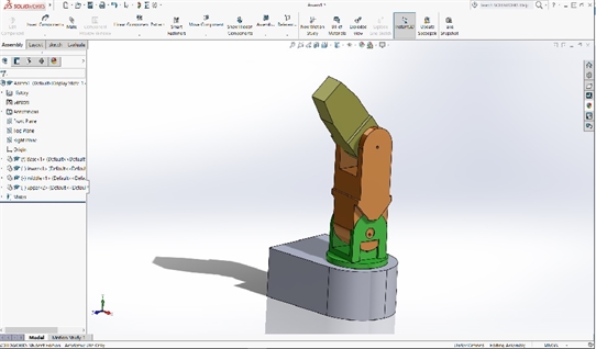
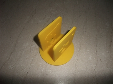
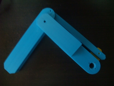
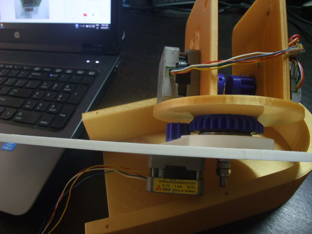
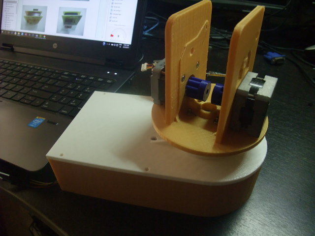
I designed and made the rotary holder this week. the pictures below show the rotary holder and how it fits together with the base boby. There will be 2 stepper motors, one on each side of the rotary holder to move 2 joints of the robotic arm
I designed and made the rotary holder this week. the pictures below show the rotary holder and how it fits together with the base boby. There will be 2 stepper motors, one on each side of the rotary holder to move 2 joints of the robotic arm

Week 10
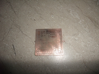
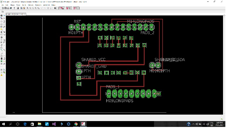
This week I redesigned a fabkit Atmega 328P board with the following modification:
- Rotate and shift 16MHz crystal to make way for additional pins
- Add 1 Vcc and Gnd pin for external use
This week I redesigned a fabkit Atmega 328P board with the following modification:
- Rotate and shift 16MHz crystal to make way for additional pins
- Add 1 Vcc and Gnd pin for external use
Assembly
Week 11
Asembling the base and rotating platform.
Asembling the base and rotating platform.
Week 13
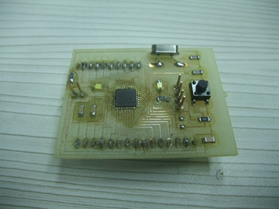
Making and testing control electronics
The robot arm is controlled by an Atmega328 board with A4988 stepper motor drivers.
Making and testing control electronics
The robot arm is controlled by an Atmega328 board with A4988 stepper motor drivers.
Firmware and Software
Week 14
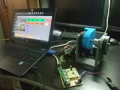
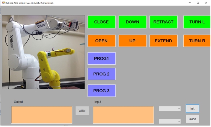
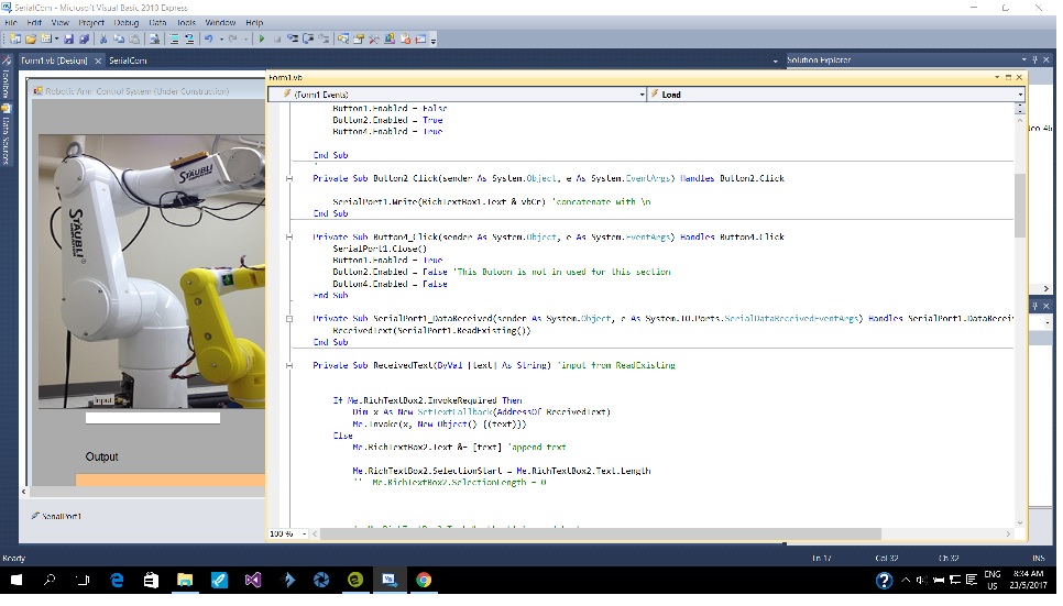
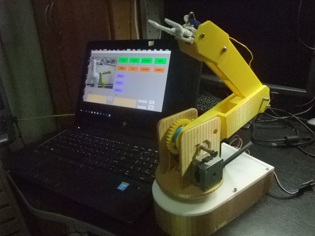
Tesing Graphic User interface, This is a test user interface running on .Net platform. The user interface link to Atmega328 board via serial link.
Tesing Graphic User interface, This is a test user interface running on .Net platform. The user interface link to Atmega328 board via serial link.
Sub system testing
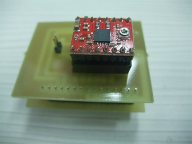
Week 16
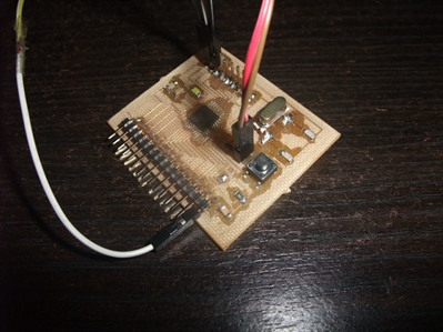
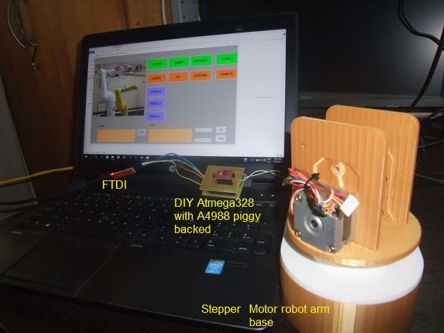
Tesing Stepper motor, From the picture you can see the FTDI board, the DIY Atmega328 with an A4988 driver module piggy backed to it, and the robot base and rotating platform with two stepper motors mounted,
Tesing Stepper motor, From the picture you can see the FTDI board, the DIY Atmega328 with an A4988 driver module piggy backed to it, and the robot base and rotating platform with two stepper motors mounted,
1st integrated test
Week 17
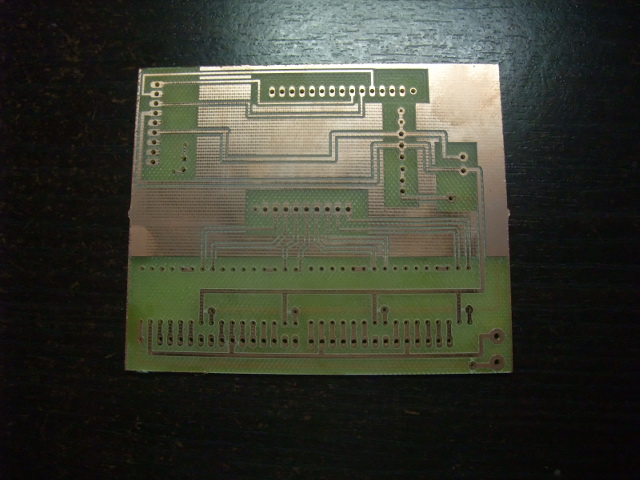
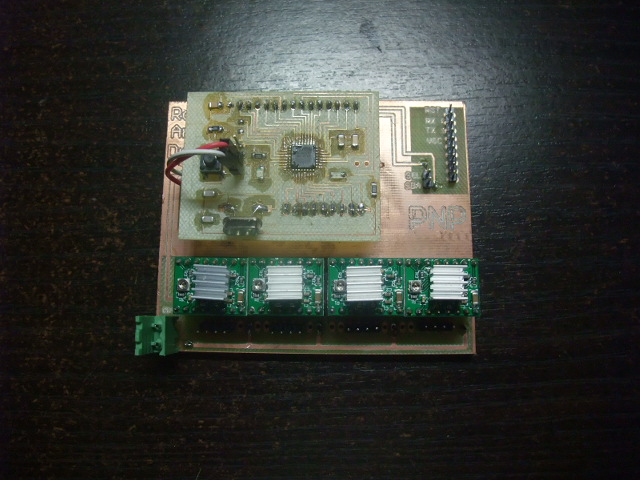
For the electronics portion. An Atmega328P I designed and made a 4 axis A4988 stepper carrier board. The board interfaces to the Atmega328P board with 2 single row connectors.
For the electronics portion. An Atmega328P I designed and made a 4 axis A4988 stepper carrier board. The board interfaces to the Atmega328P board with 2 single row connectors.
Final Assembly
Week 18
The robotic arm is not just made of 3D printed and laser cut parts, numerous type of bearing, spacer and fastener are used to provide smooth mechanical movement and minimum free play.
The robotic arm is not just made of 3D printed and laser cut parts, numerous type of bearing, spacer and fastener are used to provide smooth mechanical movement and minimum free play.
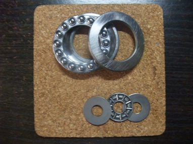
Above shows the two type of thurst bearings used. The large one(OD50mm) is used for robot base rotation and small one (OD20mm) for joint movement.
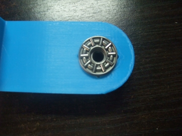
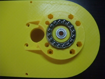
The upper right picture shows the use of small thrust bearing for lower arm movement. The picture on the lower right shows the use of large thrust bearing on robot base rotating stage.
The upper right picture shows the use of small thrust bearing for lower arm movement. The picture on the lower right shows the use of large thrust bearing on robot base rotating stage.
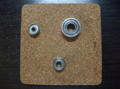
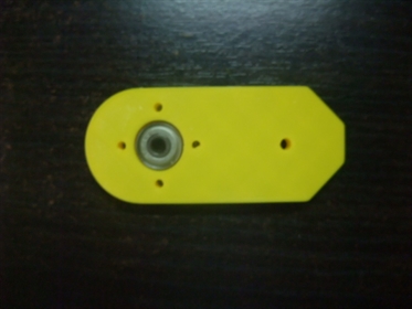
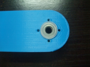
You can see the the upper left picture, 3 type of ball bearings are used, upper left in the picture is an OD12mm bearing, up right is an OD22mm ball bearing. the one at the bottom is an OD12mm flange ball bearing.
Below is a flange bearing at the upper arm joints.
Below is a flange bearing at the upper arm joints.
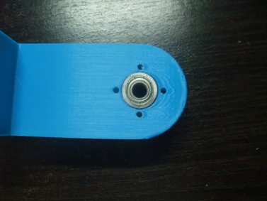
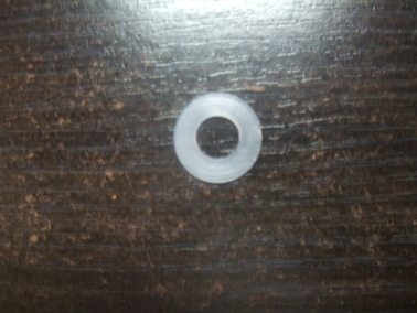
Picture below shows an OD12mm nylon washer, it is used to reduce axial free play.
All the joints are able to be moved manually before they are driven by stepper motors
First integrated test
The video below shows the inegrated test of the robotic arm with 3 axis working
The original robotic arm project spilts into 3 parts as mentioned at the beginning, each part consists of a 2 axis system(electronics, coding and mechanical). so at this stage, I have fullfilled the requirement of the final project.
Additional work
Week 19
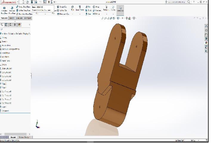
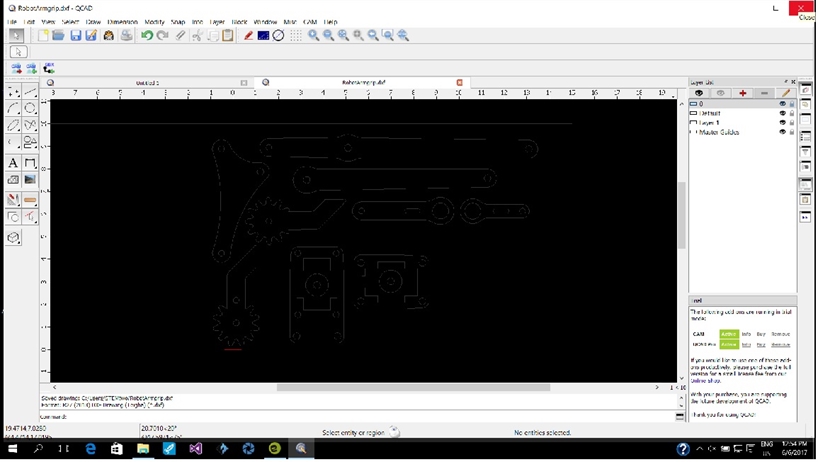
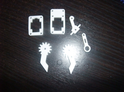
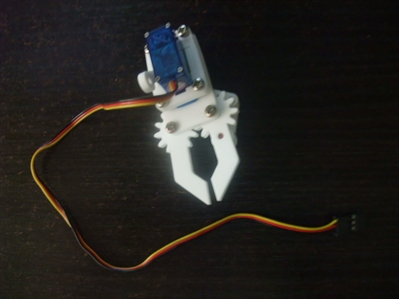
Addtional work -Laser cut gripper
Addtional work -Laser cut gripper
Week 18
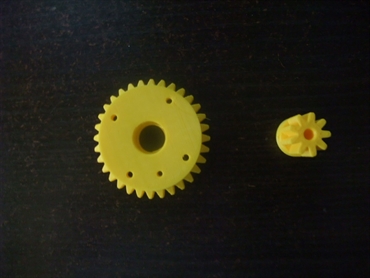
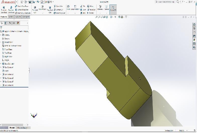
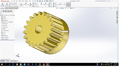
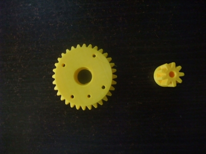
This week I designed and 3D printed the gears, lower arm and upper arm for the robotic arm project.
This week I designed and 3D printed the gears, lower arm and upper arm for the robotic arm project.
Post review
Final project 1st iteration review.
Although the project is a working one as demonstrated in the video, there are a number of area that can be further improved. They are:
1. Spur gears manufactured using 3D printing are not as accurate as metal machining. There is always some free play between gears. Even with print setting of 0.1mm per layer.
2. Stepper motor although from specification should be able to provide enough torque. But the performance much worse than expected.
2nd iteration of final project.
Since there is still a bit of time left. I have decided to embark on an improved robotic arm with the following enhancements.
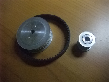
1. Use of timing belt with pulley instead of gear. Since time belt are flexible, that means they can be tensioned so give a tighter fit to the pulley.
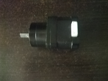
2. I have obtain some steppers with planetary gear heads. There run slower but give a much higher toque.
Although the project is a working one as demonstrated in the video, there are a number of area that can be further improved. They are:
1. Spur gears manufactured using 3D printing are not as accurate as metal machining. There is always some free play between gears. Even with print setting of 0.1mm per layer.
2. Stepper motor although from specification should be able to provide enough torque. But the performance much worse than expected.
2nd iteration of final project.
Since there is still a bit of time left. I have decided to embark on an improved robotic arm with the following enhancements.
1. Use of timing belt with pulley instead of gear. Since time belt are flexible, that means they can be tensioned so give a tighter fit to the pulley.
2. I have obtain some steppers with planetary gear heads. There run slower but give a much higher toque.
2nd iteration
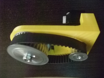
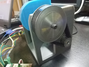
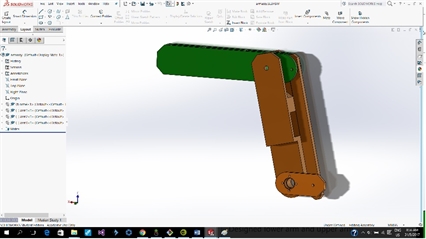
Since there is still a bit of time left, and following the spiral development methodology, I have decided to embark on an improved design, the improvements over the 1st design are:
1st design, using gear as mechanical transmission media and stepper motor to drive.
2nd design, to use timing belt and pulley as mechanical transmission media and planetary gear head with stepper motor.
For simple and quick upgrade I could just replace the stepper motors on the 1st design with the steppers with gear heads. But I think it better to go for a totally new design to make full use of the timing belt and pulley system.
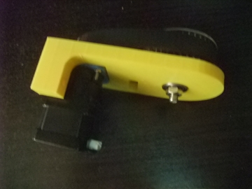
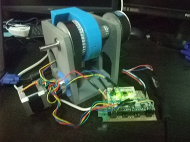
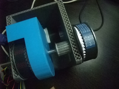
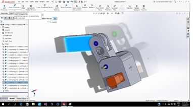
I then made a simple fixture to try out the pulleys and gear head fitting.
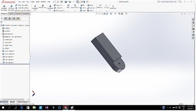
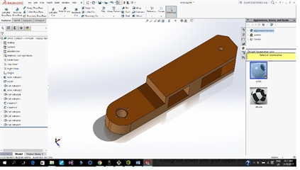
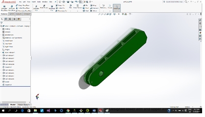
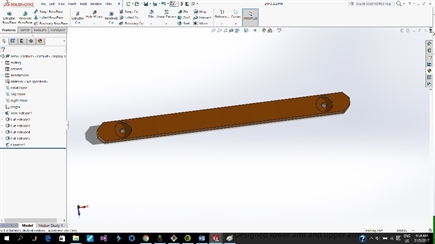
Then follow by a robot arm base design to house the lower and upper arm.
The video shows that the timing belt and pulley system works:)
1st design, using gear as mechanical transmission media and stepper motor to drive.
2nd design, to use timing belt and pulley as mechanical transmission media and planetary gear head with stepper motor.
For simple and quick upgrade I could just replace the stepper motors on the 1st design with the steppers with gear heads. But I think it better to go for a totally new design to make full use of the timing belt and pulley system.
I then made a simple fixture to try out the pulleys and gear head fitting.
Then follow by a robot arm base design to house the lower and upper arm.
The video shows that the timing belt and pulley system works:)