Final Project
The idea
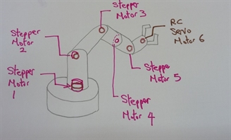
The proposed final project is a six axis robotic arm.
the project is spilt into 3 parts of 2 axis each. My project will be one of these parts.
each part will consist of the following:
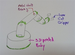
-3D design and printed body and structure
-2D design and laser cut
-Various metal shaft, bearing and fastener
-Electronic stepper motor driver board
-Embedded microcontroller baord
-Embedded microcontroller firmare coding in C
-User interface on PC developed in .net environment
the project is spilt into 3 parts of 2 axis each. My project will be one of these parts.
each part will consist of the following:
-3D design and printed body and structure
-2D design and laser cut
-Various metal shaft, bearing and fastener
-Electronic stepper motor driver board
-Embedded microcontroller baord
-Embedded microcontroller firmare coding in C
-User interface on PC developed in .net environment
Post review
Final project review
Although the project is a working one as demonstrated in the video, there are a number of areas that can be further improved. They are:
1. Spur gears manufactured using 3D printing are not as accurate as metal machining. There is always some free play between gears. Even with print setting of 0.1mm per layer.
2. Stepper motor although from specification should be able to provide enough torque. But the performance lower than expected.
Next version
Since there is still a bit of time left. I have decided to embark on an improved robotic arm with the following enhancements.
1. Use of timing belt with pulley instead of gear. Since time belt are flexible, that means they can be tensioned so give a tighter fit to the pulley.
2. I have obtain some steppers with planetary gear heads. There run slower but give a much higher toque.
The outcome


Journey of making it
Click Project Development Icon for Journey of making it from week 1 to week 20 ->
How it is made
3D and 2D designs
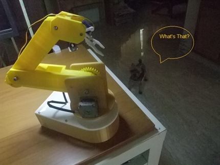
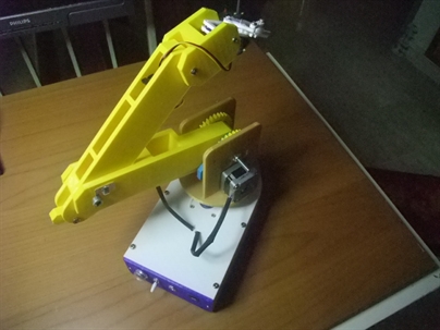
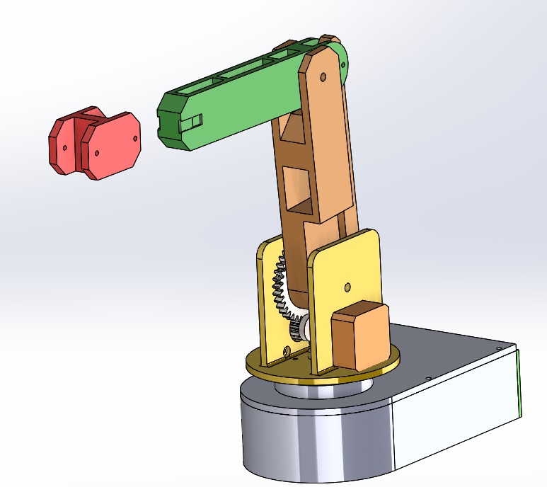
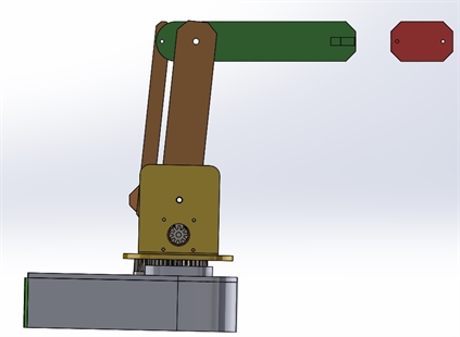
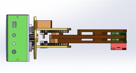
Most of the robotic arm mechanical parts are made by 3D printing with the exception of gripper which is laser cut.
From the picture below, you can see that there are 3 stepper axis(base rotation, lower arm and upper arm). The end effector shown in red is a exchangable holder. the default design comes with a ripper but can be replaced with laser engraver head, vision camera etc....
From the picture below, you can see that there are 3 stepper axis(base rotation, lower arm and upper arm). The end effector shown in red is a exchangable holder. the default design comes with a ripper but can be replaced with laser engraver head, vision camera etc....
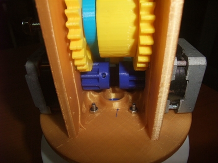
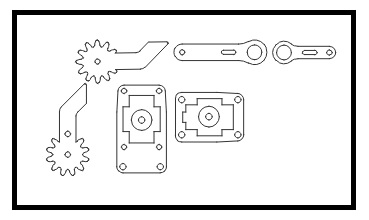
Involute spur gear trains
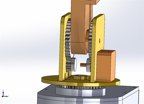
there are 3 set of involute spur gear trains driving the base rotation, lower arm and upper arm. Each gear train consists of a small gear attached to stepper motor shift and a big gear driving the axis.
Involute spur gear require machining to high precision to work properly, it is probally better machine with CNC machine rather than 3D printed.
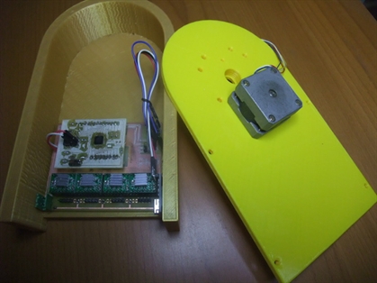
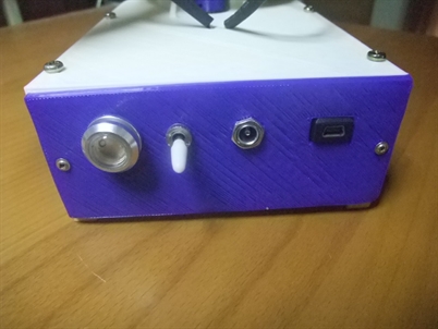
Microcontroller and stepper driver housing
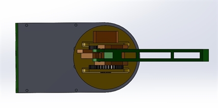
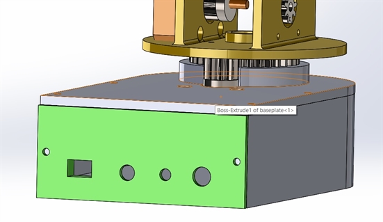
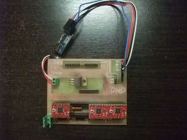
All the electronic parts are kept in the base housing. There include a DIY Atmega328 board, a DIY stepper board and a off the shelve FTDI board. All the wiring are tucked into the base housing, there are small openings for an USB socket, a12VC DC socket, an on/off switch and an indicator lamp.
All the electronic parts are kept in the base housing. There include a DIY Atmega328 board, a DIY stepper board and a off the shelve FTDI board. All the wiring are tucked into the base housing, there are small openings for an USB socket, a12VC DC socket, an on/off switch and an indicator lamp.
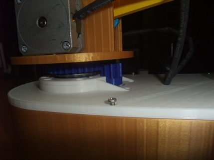
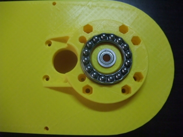
Ball bearing and thrust bearing
Ball bearing are use in most of the rotating joints and there is a large thrust bear installed for robotic arm base rotation. Manual machine operation are carried out to ensure machine can be hand moved before they are driven by motors.
Ball bearing are use in most of the rotating joints and there is a large thrust bear installed for robotic arm base rotation. Manual machine operation are carried out to ensure machine can be hand moved before they are driven by motors.
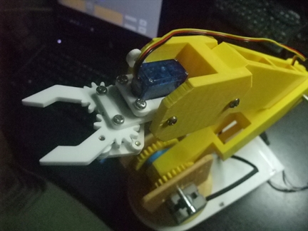
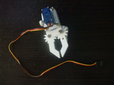
2D design and laser cut gripper
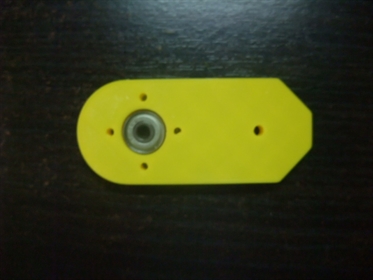
The default end effector is an 3mm acrylic laser cut gripper.
The default end effector is an 3mm acrylic laser cut gripper.
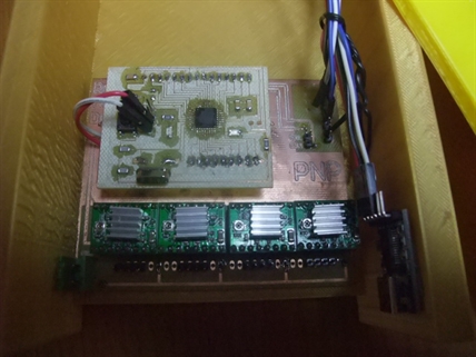
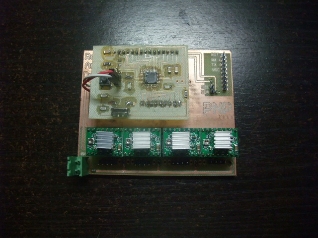
Electronics
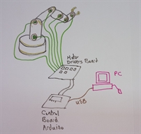
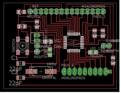
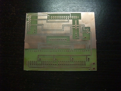
The electronics portion of the robotic arm consists of a Atmega 328P microcontroller and 4 A4988 module. The initial idea was to put everything in one single side PCB. However during design phase, it was discovered the board size exceeded the maximum board size allowed by the free version of Eagle CAD software. As such, the microcontroller board became a single sided PCBA mounted on a 2 sided stepper board.
Microcontroller board
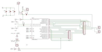
The Atmega 328P microcontroller board is based on the Satshakit but with the following modification done
1. Addition of VCC and Gnd pins
2. Relocation of 16MHz crystal Y1 to make space for additional VCC, GND pins
3. Relocation of 22pf capacitors C1 abd C2
4. Relocation of resistor R3
5. Change right angle headers PADS1 and PADS 2 to straight type
6. Change Y1 crystal to PTH type due to component availability
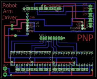
Stepper driver board
The stepper driver board consist of the following
1) Connectors for external DC12V for the stepper drivers and DC5V for the microcontroller
2) Connector for FTDI board
3) Direction and Step signal connection to microcontroller for each stepper driver
4) Filtering capcitors for A4988 driver.
Later on, I discovered that using two power supply 12v and 5v is cumbersome, so a 7805 5V power regulator was manually added. This will be included in the next PCB design.
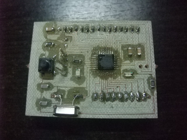
Testing of microcontroller board and Stepper driver baord
Firmware and Software
Software on PC
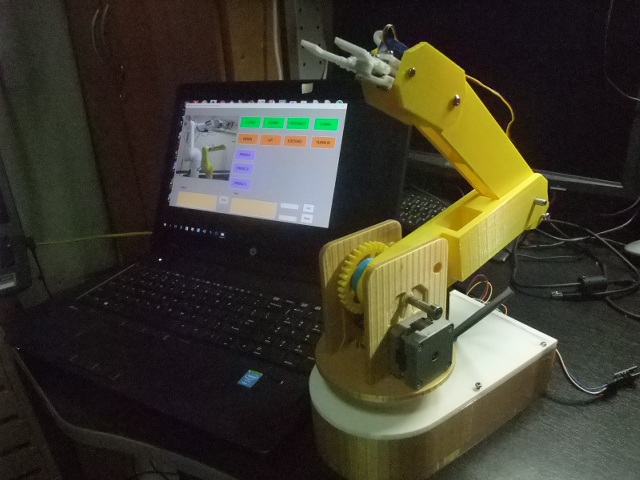
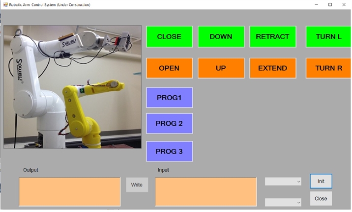
For testing purpose, I have develop this simple user interface running on .Net platform. which time a command is sent from PC to the robotic arm microcotroller, the coresponding axis move 100 steps.
The robotic arm is also designed to be GRBL competiable. For normal operation , the robot can also be run with opensource G-code sender such as Repetier Host or Printrun.
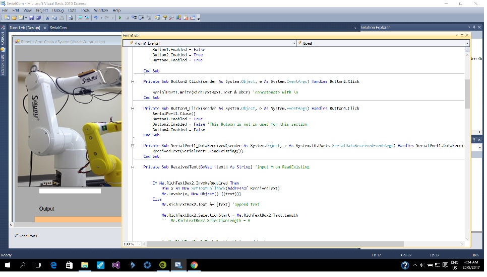
Firmware on Microcontroller
For testing purpose, I have developed simple arduino program to recieve commands from PC and move each coresponding axis is 100 steps.
The robotic arm under normal condition can also be run with free opensource G-code interprator such as Merlin.
For testing purpose, I have developed simple arduino program to recieve commands from PC and move each coresponding axis is 100 steps.
The robotic arm under normal condition can also be run with free opensource G-code interprator such as Merlin.
Accessories
These are optional designs that are extra and beyond the final project scope. they can either be mounted on as end effector or attached to the robot to enhanace the robotic arm's performance. Most of the items are still under development excapt the gripper.
The gear head stepper motor has a gear ration of 10:1, it is a direct replace for the stepper driver lower and upper arm. It will increased the driving torque of the robotic arm as least 5 folds.
The gear head stepper motor has a gear ration of 10:1, it is a direct replace for the stepper driver lower and upper arm. It will increased the driving torque of the robotic arm as least 5 folds.
Gripper (see above)
Gear head stepper motor
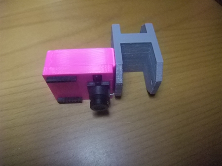
Laser engraver head (under testing)
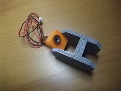
Machine vision camera (under testing as shown in week13 input device)
Mounting foot
Gear head stepper motor
Laser engraver head (under testing)
Machine vision camera (under testing as shown in week13 input device)
Mounting foot
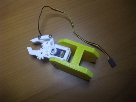
This is the default accessory for the robotic arm.
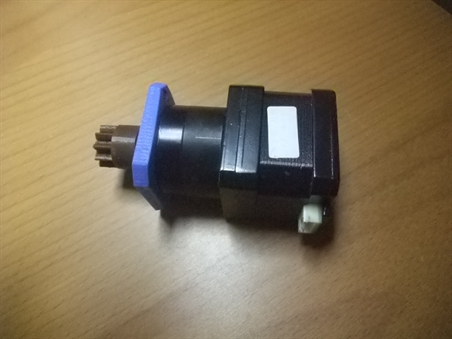
This gear head stepper motor will increase the torque available for lower and upper arms. That means the robotic arm will be able to lift heavier thing. It is a direct drop in replacement for the existing stepper motor.
This is a low power laser engraver head. it allows engraving to be done on light material such as paper or wood
As shown in in the input device assignment, the machine vision camera can be used to track and identify object, thus providing guidance for the robotic arm.The vision camera is mounted on the side of end effector, leaving space for a gripper if needed.
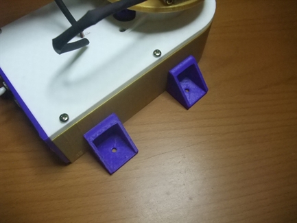
Four of these mounting foot and some screws will hold the entire roboitc arm firmly on work surface, even when the arm is moving in higher speed, and it would not topple when lifting heavier object.
Packaging
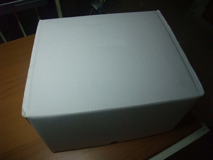
Shipping box
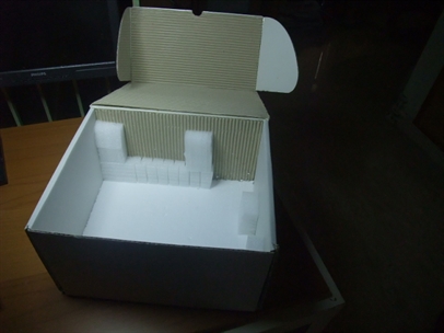
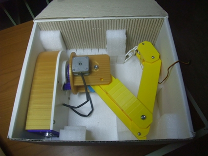
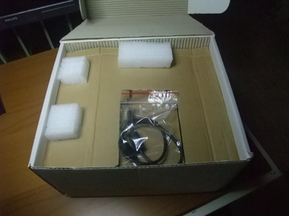
This is a handmade shipping box that I have made for safe storage and shipping of the robotic arm. it will be laser cut in future in needed
This is a handmade shipping box that I have made for safe storage and shipping of the robotic arm. it will be laser cut in future in needed
Disclaimer
This is a school project. You are free to download and use the information here under the "Creative Commons Attribution-NonCommercial-ShareAlike 4.0 International License". I will not be responsible for any outcome (such as your dog bites you because you love the robotic arm more than him/her) as a result of using the information. If you are able to get your robotic arm to work, congraturation. You are there already. If not, my best piece of advice is, enroll for next run of fab academy course, Neil has all the answers you need.
This is a school project. You are free to download and use the information here under the "Creative Commons Attribution-NonCommercial-ShareAlike 4.0 International License". I will not be responsible for any outcome (such as your dog bites you because you love the robotic arm more than him/her) as a result of using the information. If you are able to get your robotic arm to work, congraturation. You are there already. If not, my best piece of advice is, enroll for next run of fab academy course, Neil has all the answers you need.
Contact
I can be contacted at:
Kennyphay38@gmail.com
I can be contacted at:
Kennyphay38@gmail.com