
Until 22 Mar 2017
Embedded Programming
FabKit I/O v2
Contents
- Learning Basics
- Programming 'Hello Kuri' boards
- Making FabKit. aka Fabduino
- Programming the FabKit with FabISP and Arduino IDE
- Programming the FabKit with FTDI
- 8th The Fab Academy meeting
Basics
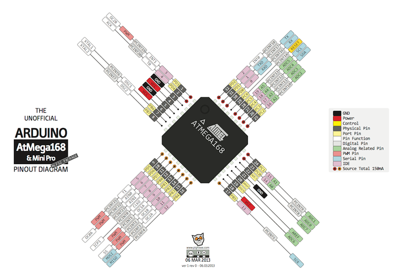
READING: microcontroller data sheet
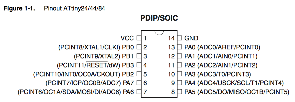
I read abaout ATtiny24A/44A/84A. Attiny44 has 1 VCC pin, 1 ground pin, 4 pins for PORTB which is 4 bit I/O port (PB0 to PB3), and 8 pins for PORTA which is 8 bits I/O port (PA0 to PA7). Attiny44A is a 8-bit AVR microcontroller that contains 4K bytes In-System Programmable Flash. Voltage supply of 1.8V ~ 5.5V. The oscillartor types are Internal (128 kHz & 8 MHz) and external (20 MHz)
Programming 'Hello Kuri' boards
I made 'Hello Kuri' board and programmed to do blinking and using botton on week 6.
I also made flexible 'Hello Kuri' board as part of Textile Academy Bootcamp.
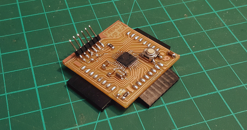
Making FabKit. aka Fabduino
Reference:
+ Fabkit i/o (aka Fabduino)
+ Fabkit v.0.3-0.4
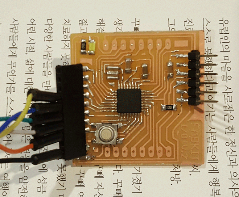
I'll be making FabKit version 0.4
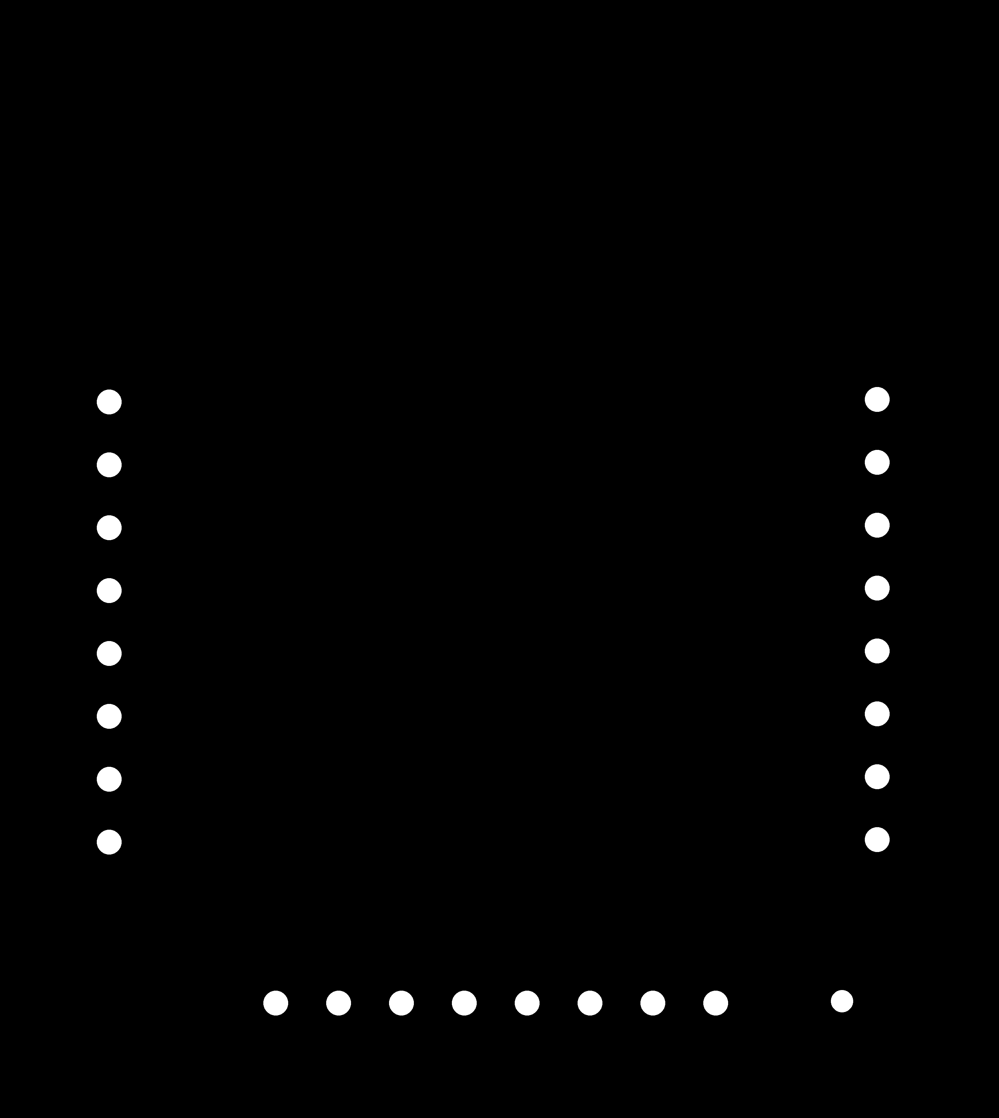
Traces
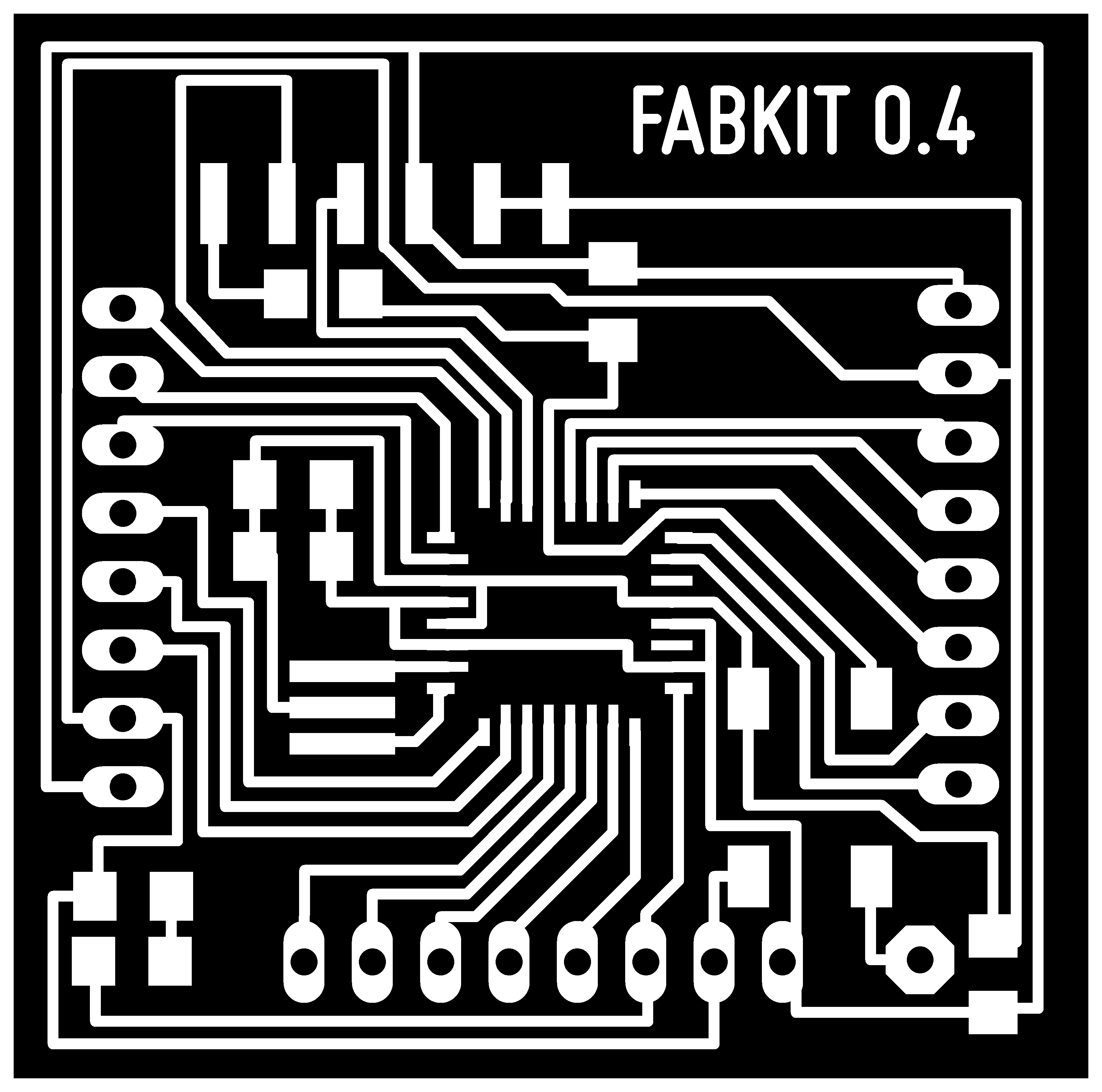
After milling PCB I realized that my lines were connected. I should've checked the Fab Module calculation before saving the files to mill.
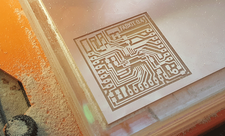
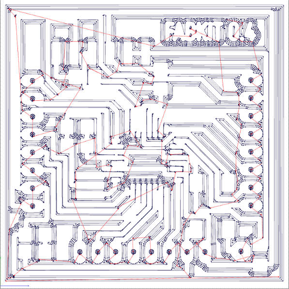
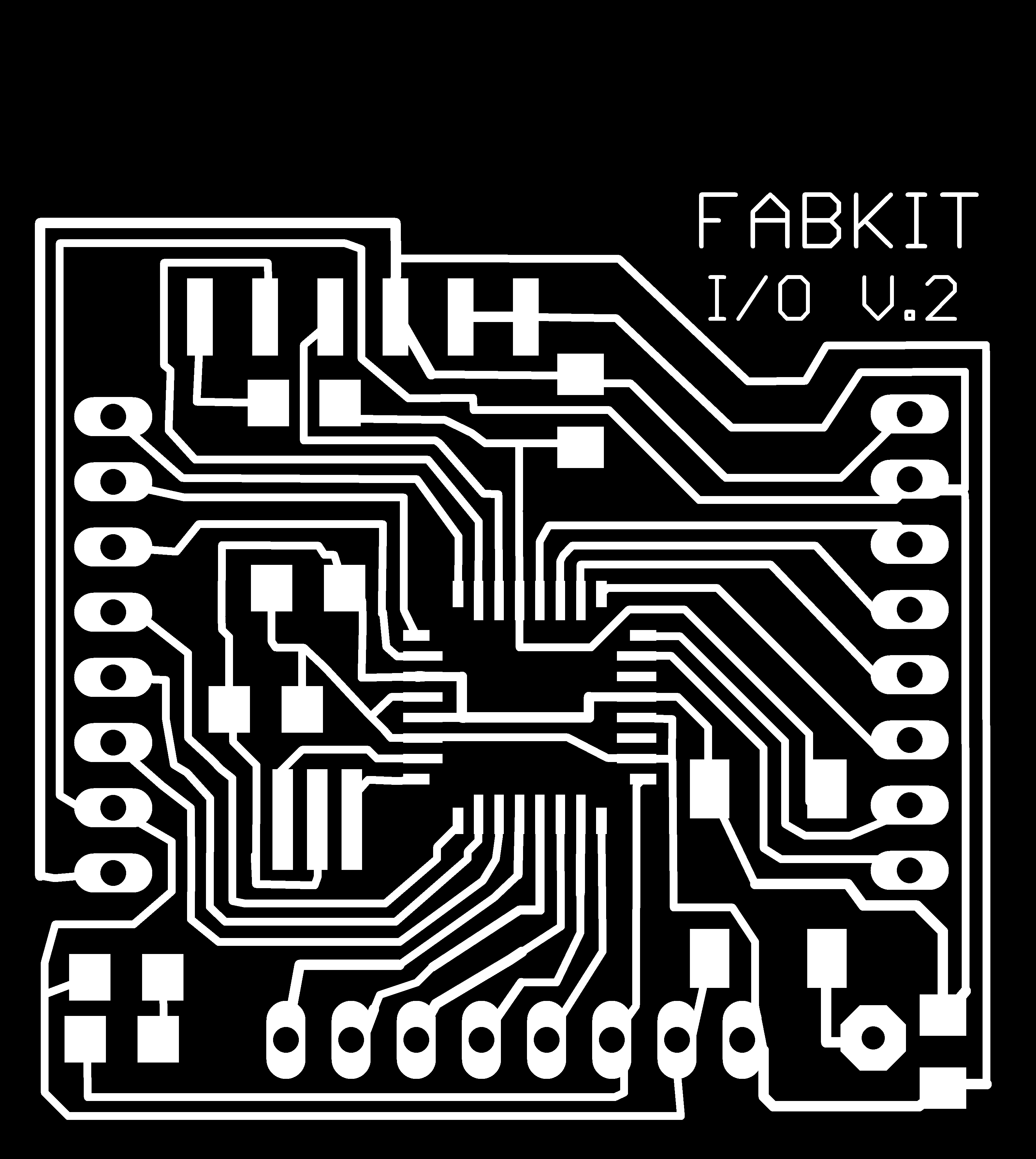
So Edu suggested me to do the Fabkit I/O v.2.
Materials for FabKit
+ 1 Atmega 168
+ 1 Crystal 8 MHz (resonator) 535-10004-1-ND
+ 1 Capacitor 10 uF
+ 2 Capacitor 0.1 uF
+ 1 Capacitor 1 uF
+ 1 Resistor 10 K
+ 1 Resistor 499 ohm
+ 1 Led
+ 1 FTDI 3.3-5V
+ 1 8 male pin connector
+ 2 8 female pin connector
+ 1 button SMD
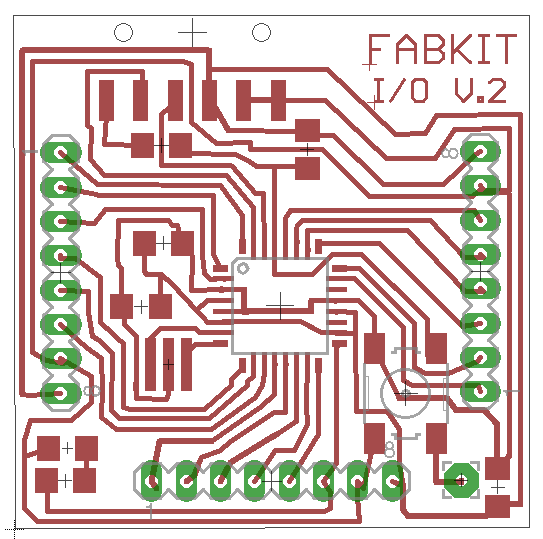
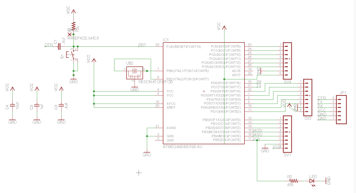
Link to download Eagle board and schematic files.
Programming the FabKit
I've used make.file to program my ISP, so I've decided to use Arduino IDE to program my fabkit.
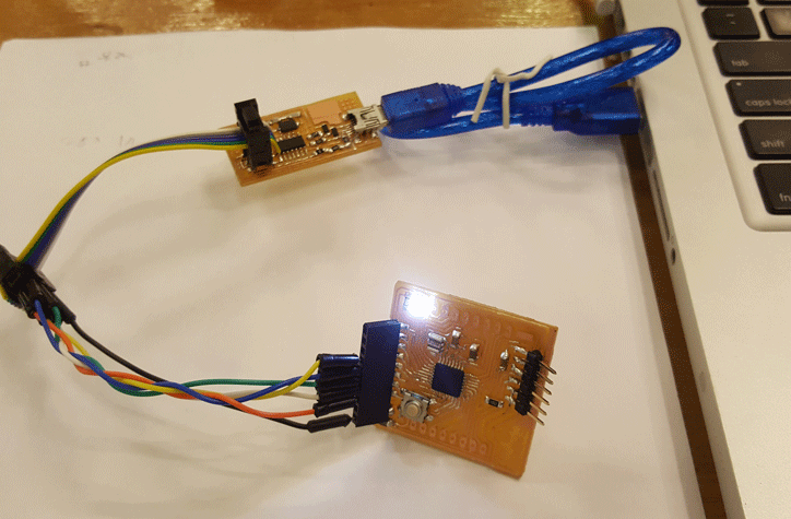
Reference: HyunGu Jung's Fab Academy Archive. He used same FabISP and FabKit, so I was able to understand what's going. To be able to program, I need to know how FabISP(5V, GND, SCK, MISO, and MOSI) pins and FabKit connects. One Last pin goes to reset pin.
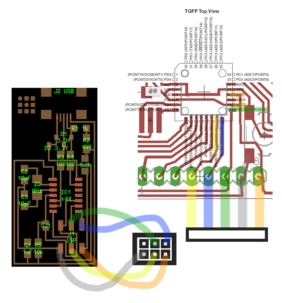
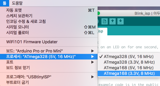
Because I put external 8mhz resonator I didn't have to install additional files, I used the "arduino Pro or Pro Mini, ATmega 168(3.3V, 8MHz" setting.
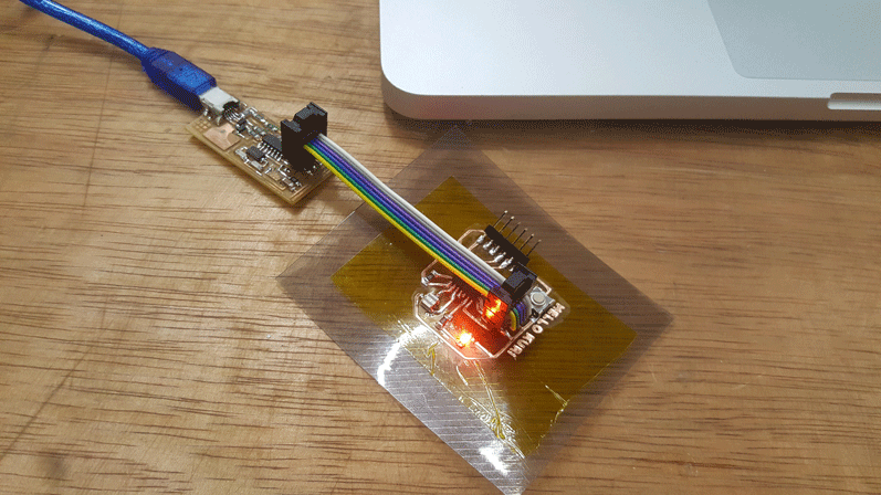
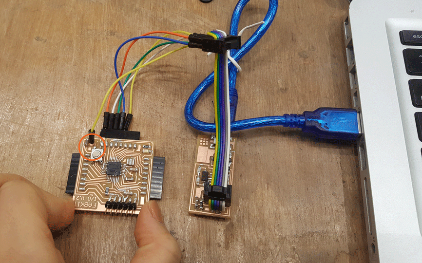
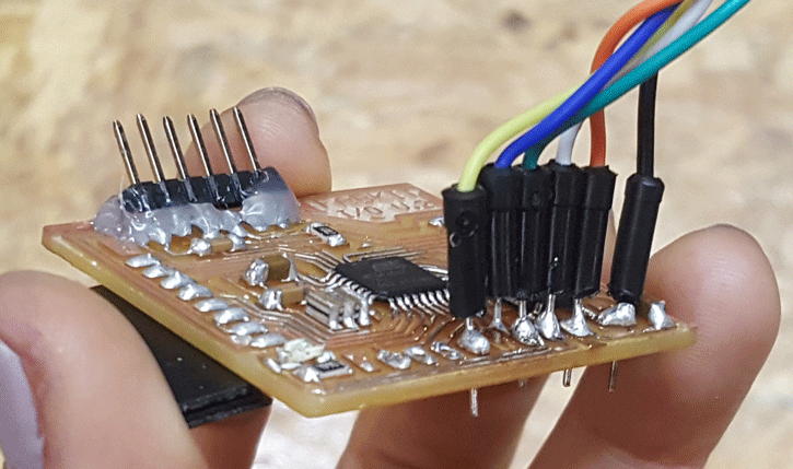
There are two problem with the photo below. I didn't solder the yellow wire. Plus, FabISP and FabKit is not connected right direction.
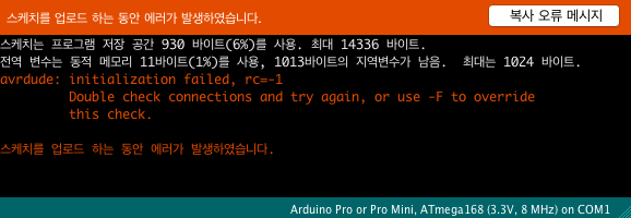
Right direction, and soldered my last wire but I still have error message.
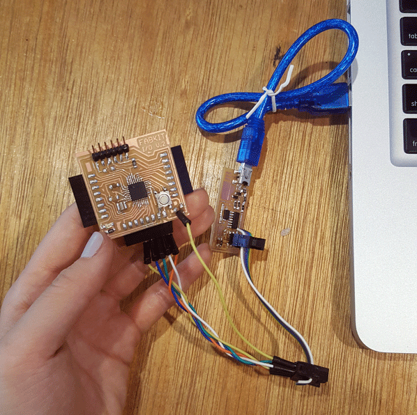
I tried to just ignore and upload this program and of course I had problem.
I've tried different methods to bootload my Fabkit but it doesn't work. I solder and resoldered it too many times. I ended-up with broken Fabkit.
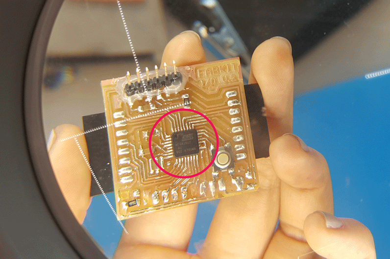
The problem with my Fabkit wasn't about soldering or my lack of programming skill. It was the ATmega. I was using MEGA16U2-AU instead of MEGA168-15AT. After changing it. IT WORKS!!!
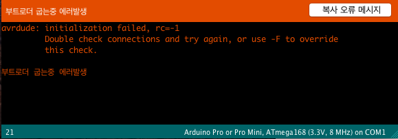
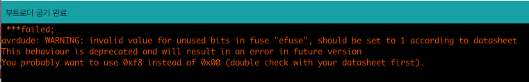
After uploading bootload with Edu's computer. I went to my computer and bootload again. Bootload was completed, but this came up and I don't know why this error means.
Finished!!!
I was able to program blinking using Arduino software and my FabISP. I was just playing around with simple sketches.
Programming the FabKit with FTDI
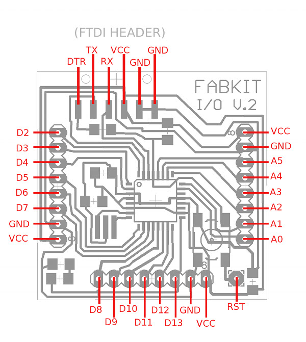
I found this image online
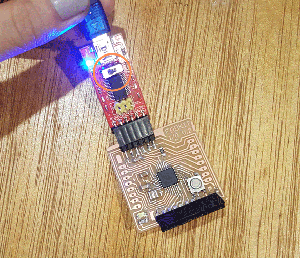
When I tried to use FTDI for programming without changing any settings. Of course, it didn't work at first. I had to change arduino IDE to the port(tool>port>/dev/cu.usbserial-AH02UDCX), the board setting (tools>board>Arduino Pro or Pro Mini), processor(Atmega328, 8mHz) and bootloader once again. Make sure that the FTDI swich to the left to make 5V to 3.3V.
At the beginning I had no skills in programming but as a result, I was able to programmed my FabISP in week4 with c language, echo hello-world board using FabISP and Arduino IDE in week 6, and Fabduino with FTDI this week.
Simple blink using library.
// the setup function runs once when you press reset or power the board
void setup() {
// initialize digital pin LED_BUILTIN as an output.
pinMode(13, OUTPUT);
}
// the loop function runs over and over again forever
void loop() {
digitalWrite(LED_BUILTIN, HIGH); // turn the LED on (HIGH is the voltage level)
delay(4000); // wait for a second
digitalWrite(LED_BUILTIN, LOW); // turn the LED off by making the voltage LOW
delay(100); // wait for a second
}
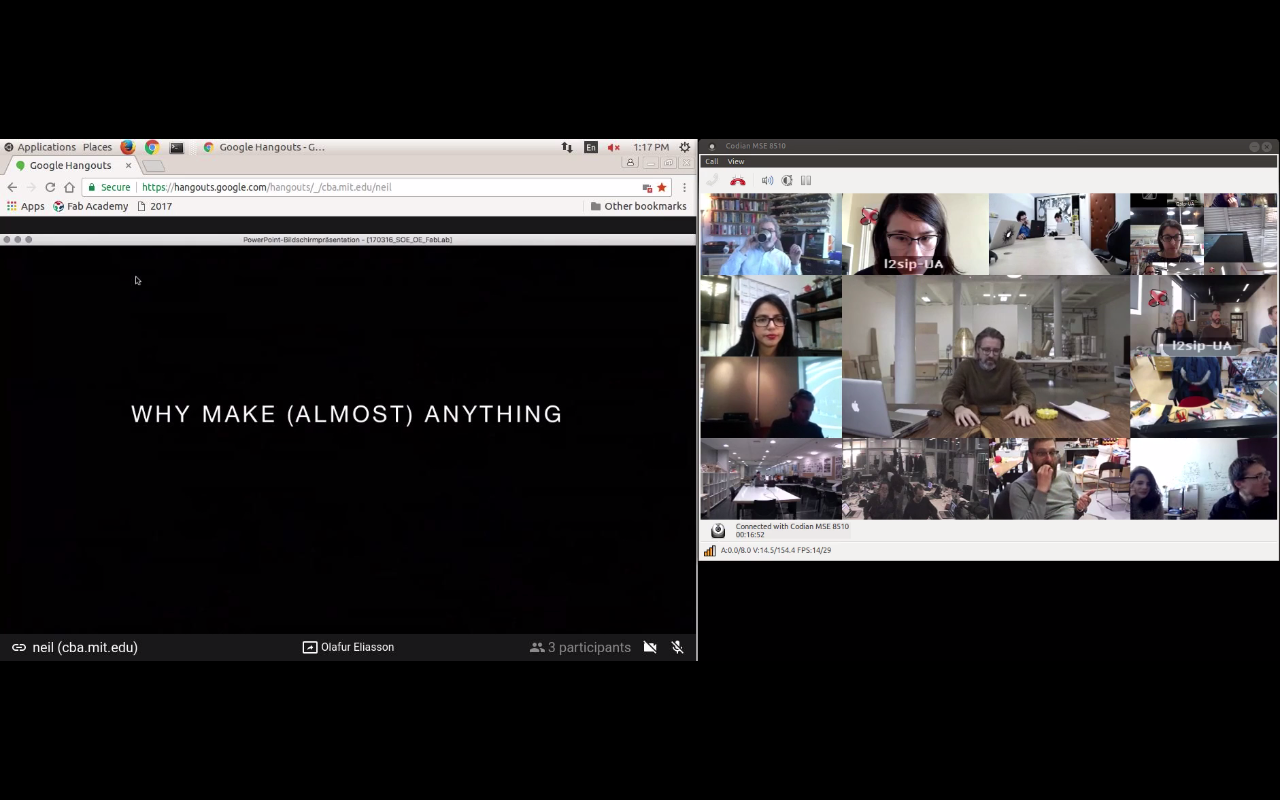
OLAFUR ELIASSON!!!!!! March16, 2017. Why Make(almost) Anything.
I'm SUCH A BIG FAN!! I couldn't join the video chat, but I saw the vimeo recording. I became a big fan after going to the solo exhibition in Leeum Museum in Seoul last summer. I didn't realize that the Lego project in NYC Highline was by Olafur Eliasson! I was there too!
#smilingworks Project
Make a work of art using a smile, social artwork. Find a contents and platform, it could be a large scale of smile, or using different equations of smile.
8th Meeting:
embedded programming March 15, 2017 10pm~1am(Seoul)
Homework
o - Read a microcontroller data sheet
o - Program your board to do something, with as many different programming languages and programming environments as possible