Electronic production. Learning something new!
Assignment
Make an in-circuit programmer by milling the PCB, then optionally trying other processes (USE: USB power, make clean,make hex, (sudo) make fuse (check programmer in Makefile, may need to repeat), (sudo) make program desolder SJ1 and SJ2,make IDC ISP cable, connecting header pin 1 to pin 1, check wires))
Deciding between Brian’s (image at the left) and David´s (image at the right) version:
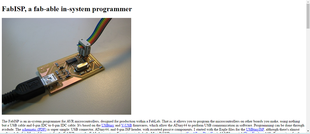
For this week we had to fabricate the first PCB board with the Roland MonoFab SMR-20 (Machine available at my Lab). I decided to use Brian´s Design of the FabTinyStar, form all the different options we had:
“The FabTinyStar is yet another version of an AVR ISP programmer/board that can be produced in a fab lab using a milled PCB and readily available components. The project is based on the efforts of many people. For more history of the FabTinyStar and the people who have contributed to it, please refer to Zaerc's FabTinyStar." Refer to Brian´s Page for details
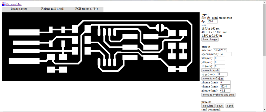
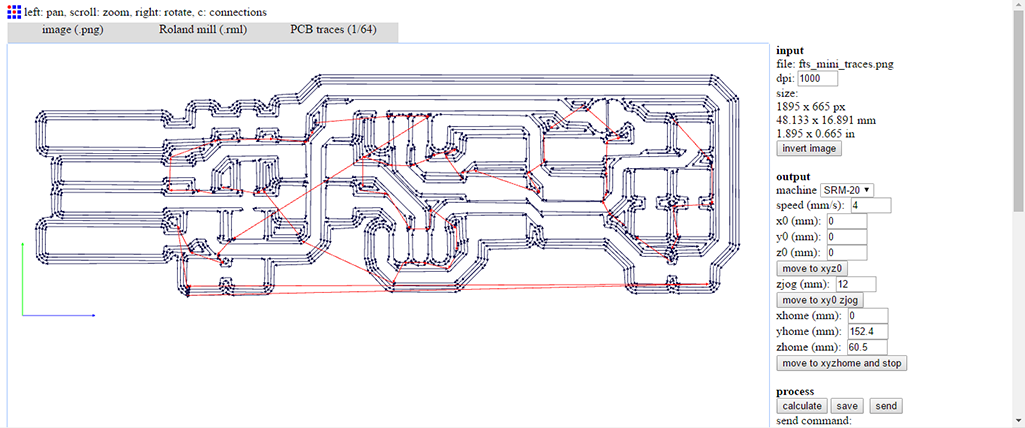
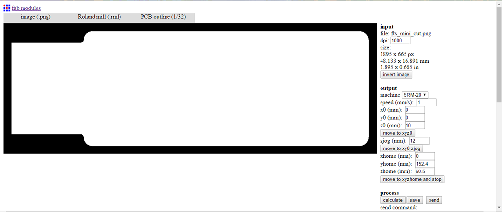
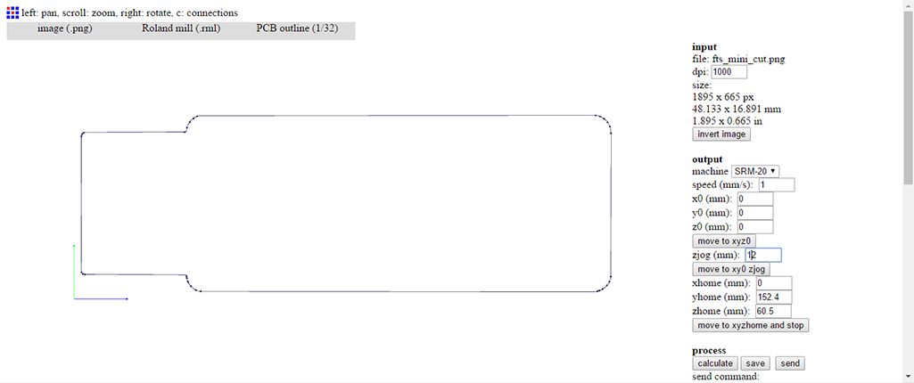
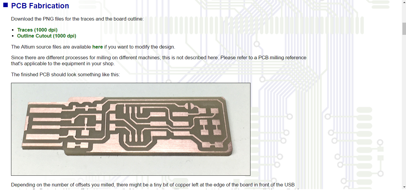
The first step was to download the .png files for milling and cutting. These files as them self don’t actually work in the machines software, so what you have to do is enter them into the FabModule page so that you can create a language for the machine, in other words to allow cut and mill. As you can see un images above.


Before you start milling you have to set up the machine, for this you have to do it manually. After everything is set you just enter the file and press CUT on the software.(image at the left)
- Adjusting the tool into the machine
- Identify the correct tool and make sure is suitable for cutting
- Place the copper tablet on the milling bed
- Make sure everything is on its place
Try one on milling didn’t went well as you can see(image at the right).


Here are some examples of good and bad milling. This can be cause by different things: bad calibration of the machine since apparently the milling process was not working and we thought that may be a problem that involved identifying which part of the machine was not working correctly (as Neil expose in the class) but this was not the case; Z axis not position as close as the material as possible or in my case; the tool was broken and didn’t cut well. You can see the different tries above.
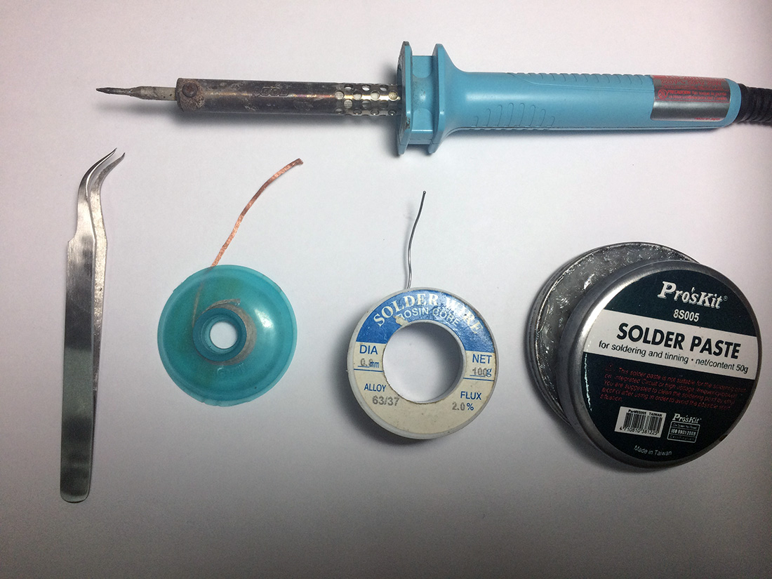
TOOLS NEEDES: We started practicing with some soldering introduction and the tools needed this where (image at the left):
- Solder Iron
- Curve Tweezer
- Solder WickSolder wire
- Solder paste
Additional (Not in images):
- Soldering Iron Stand
- Alligator Clips
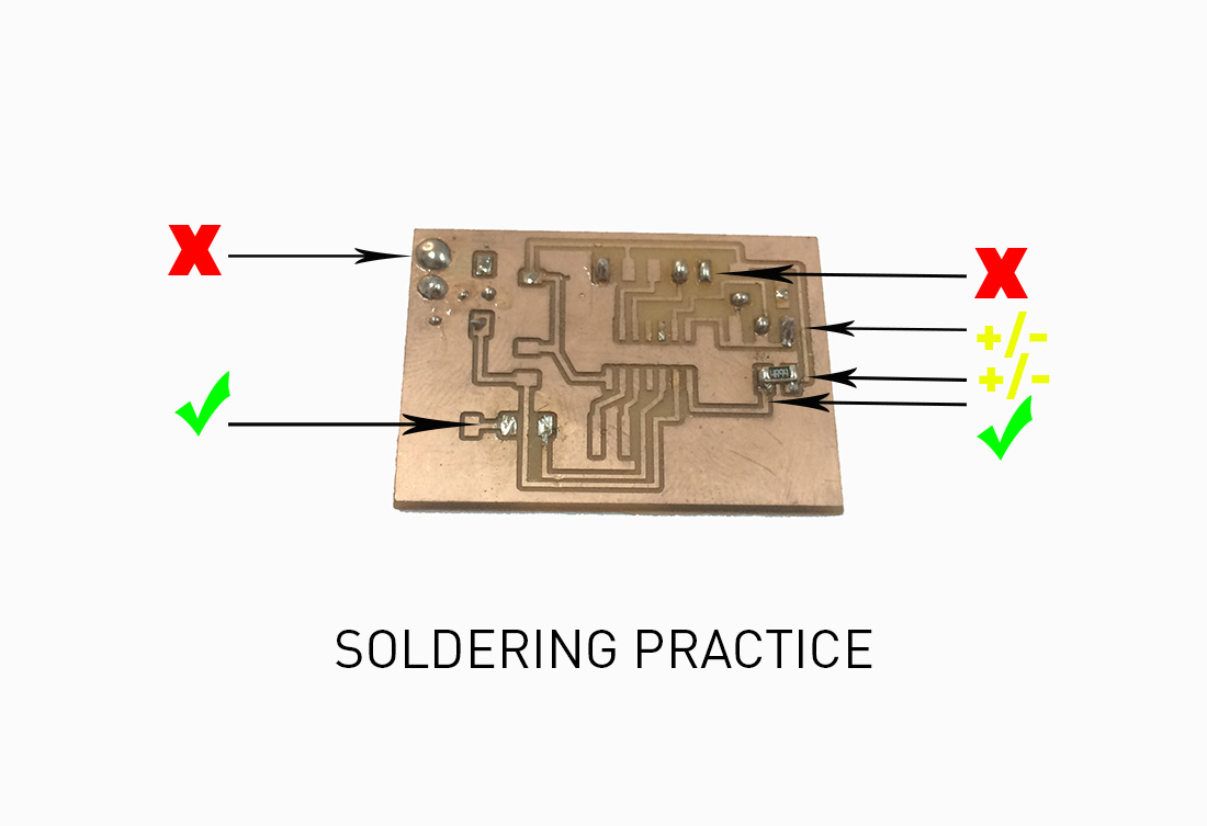
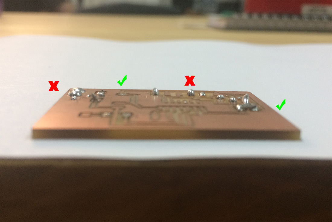
Here are some examples of good and bad soldering above(center and right images)


After we bought the new tool we made some more milling, TIPS:
- Make sure you place the circuit board blanks with double side tape and that is well paste
- First Trace
- Second Cut
See process(images above)
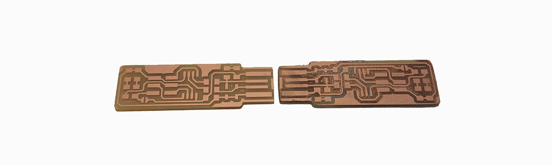
In the images above you can see the difference between a good (image at the left) and bad (image at the right) milling.
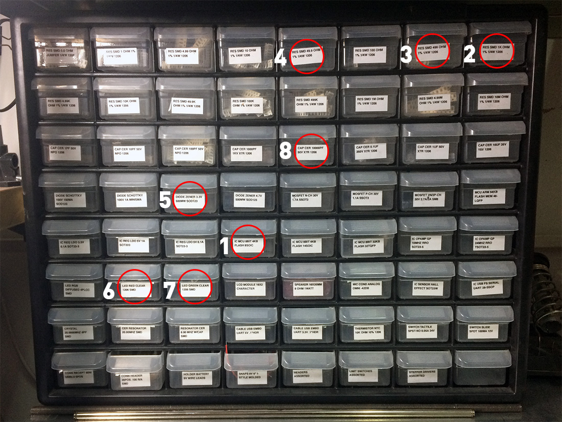
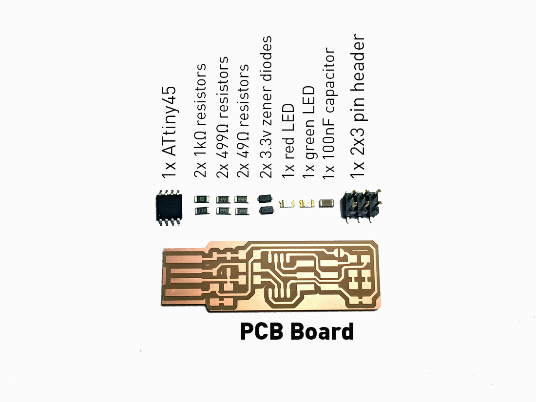
Searching for components:
- (1) 1x ATtiny45 or ATtiny85
- (2) 2x 1kΩ resistors TIP: identify in component as 1001
- (3) 2x 499Ω resistors TIP: identify in component as 4990
- (4) 2x 49Ω resistors TIP: identify in component as 4992
- (5) 2x 3.3v zener diodes
- (6) 1x red LED
- (7) 1x green LED
- (8) 1x 100nF capacitor
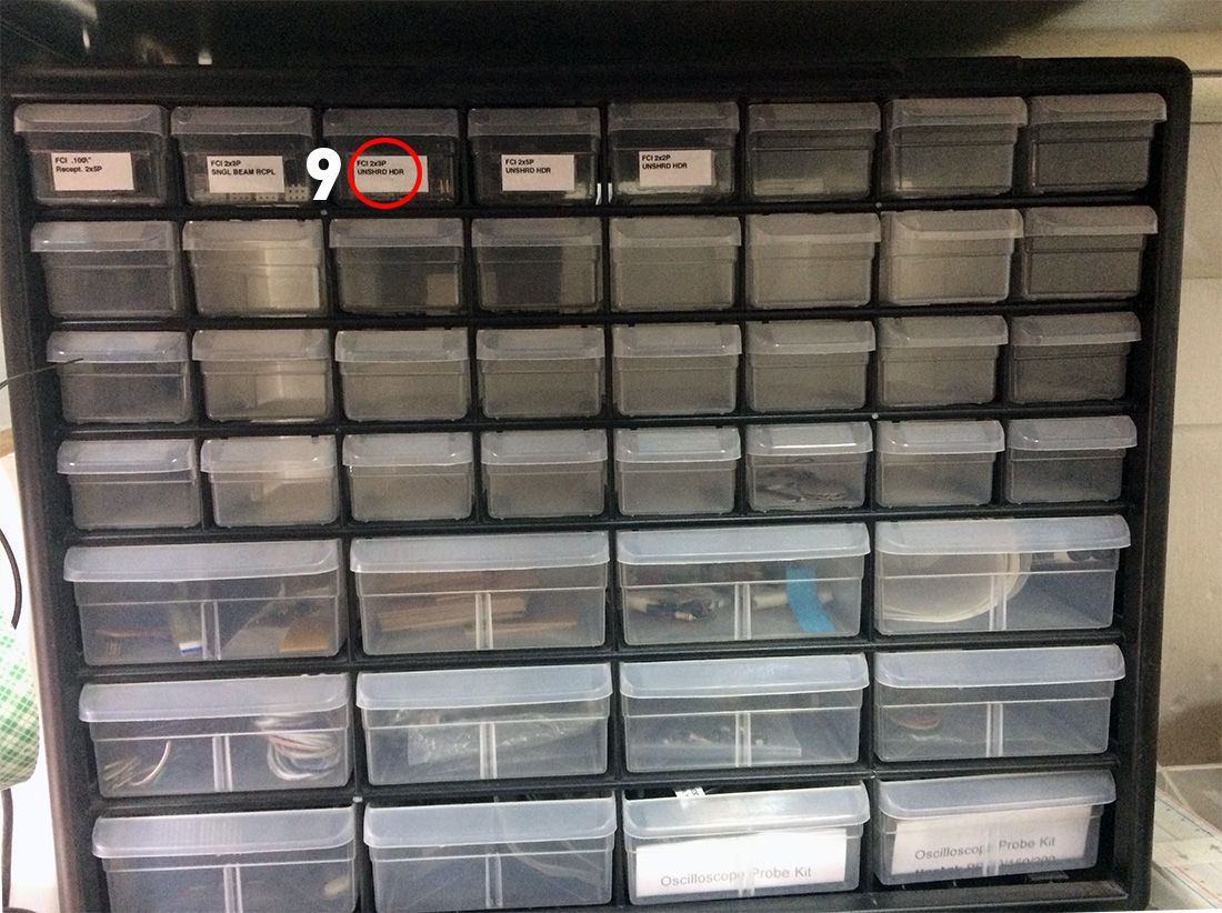
- (9) 1x 2x3 pin header
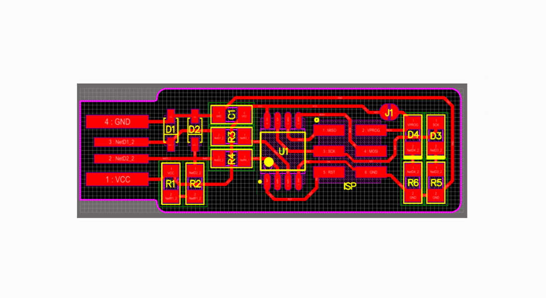
To start soldering components (image at the left) on to your PCB help yourself with a design image (image at the right)
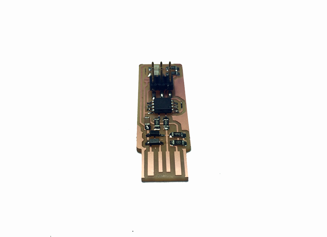
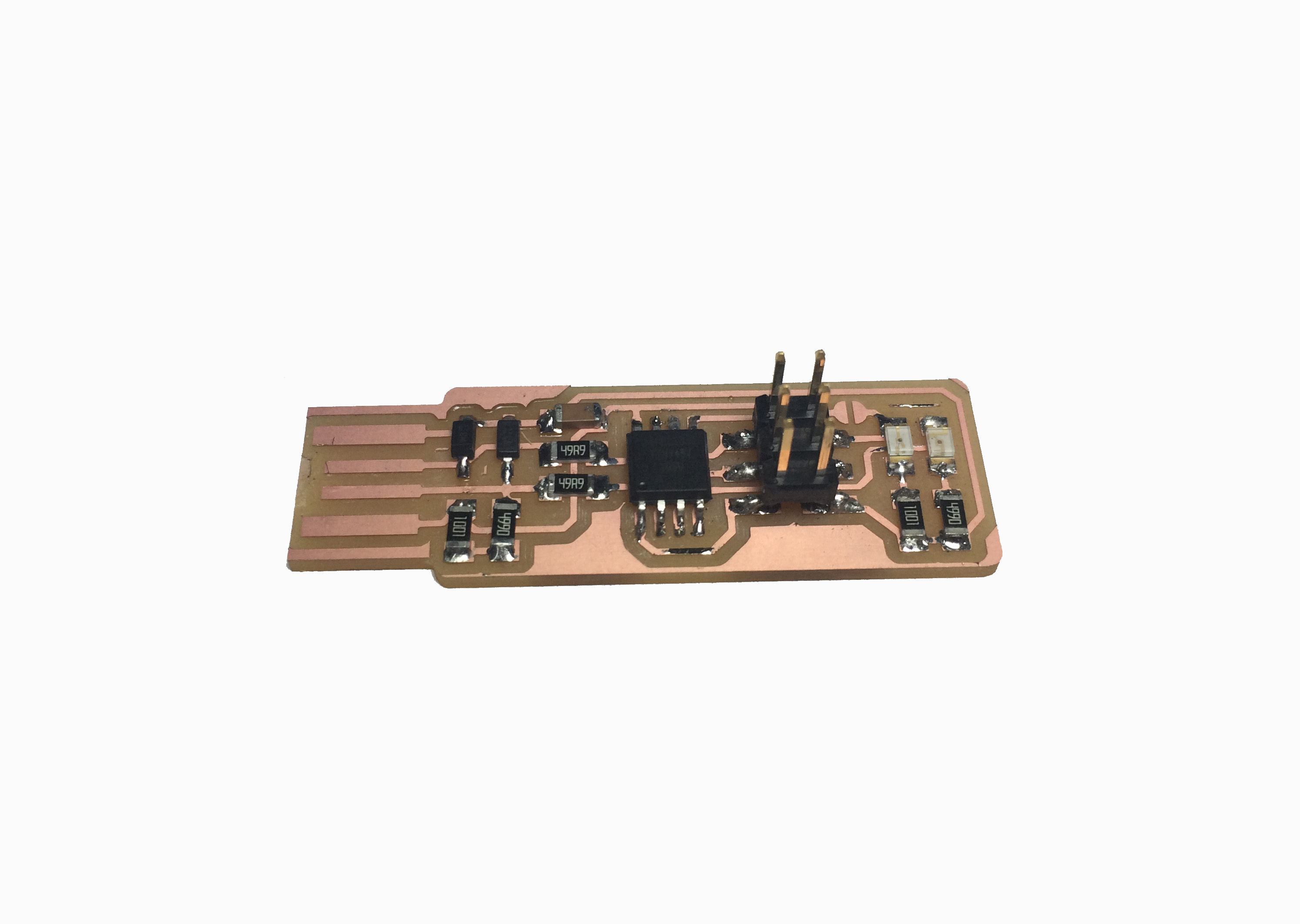
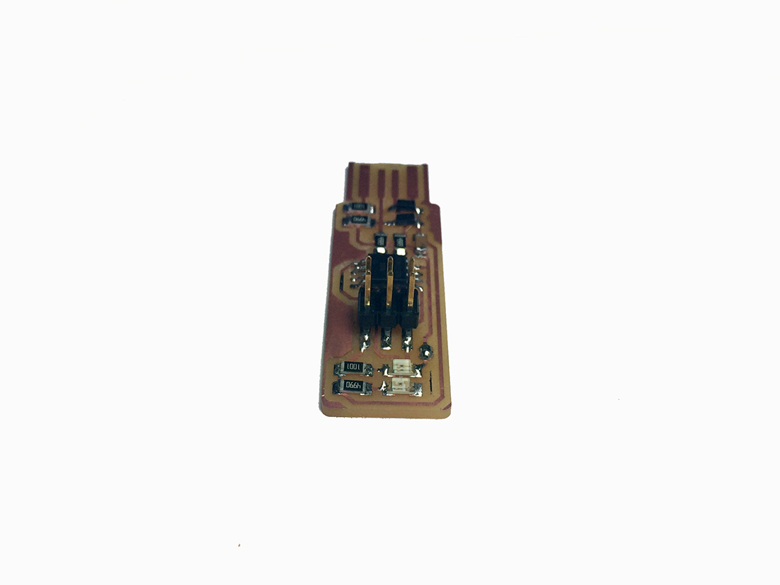
Frist step done, PCB is traced, cut and components are solder!(images above)
MY FIRST STEPS PROGRAMING
For Windows you need to Download the following softwares in the following order
- Git Bash
- Atmel AVR Toolchain
- Gnu Make
- Avrdude
- Cygwin Windows Users Recommendation
- Zadig Windows Users Recommendation
- For more information please visit: Brian´s Page 1 or Brian´s Page 2
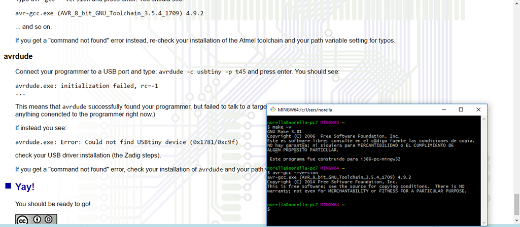
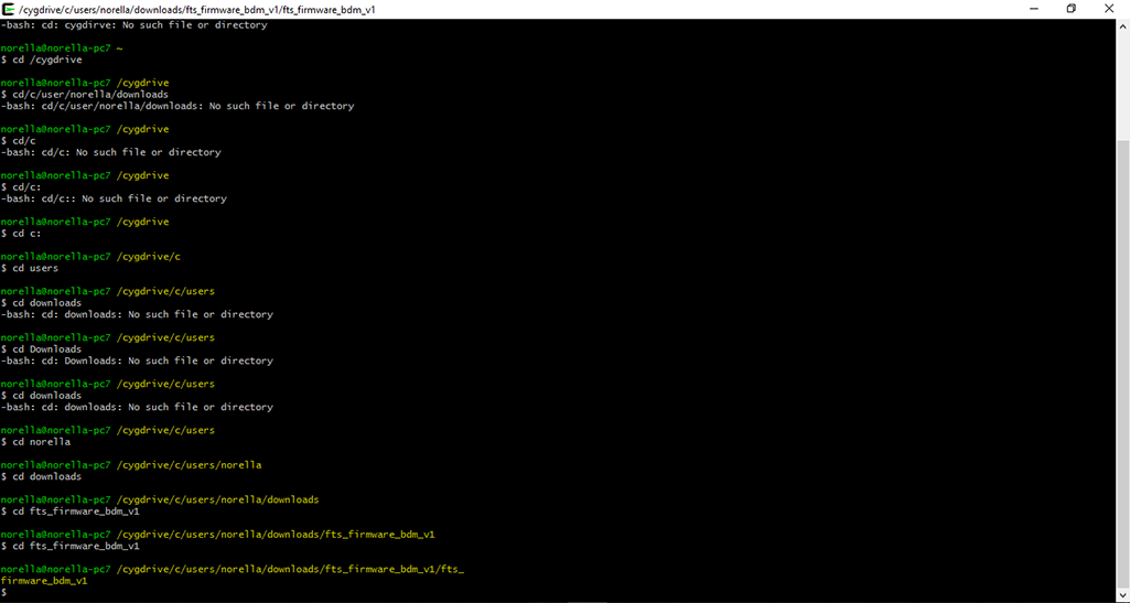
Once everything is now installed. Let's check that it all works. Go to the start menu and search for "Git Bash" and start it. When you see instructions telling you to open your terminal in other tutorials, this is the terminal window you should use. Check to make sure that the commands we installed work okay (image at the left)
Commands:
- make –v
- avr-gcc
- avrdude -c usbtiny -p t45
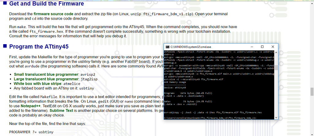
Now programming starts, update the Makefile for the type of programmer you're going to use to program your board. The Makefile, by default, assumes that you're going to use a programmer in the usbtiny family (e.g. another FabISP board). If you're using a different programmer, first figure out what avrdude (the programming software) calls it. (image at the right)
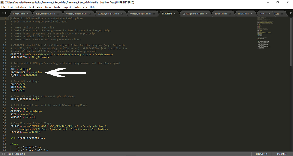
Near the top of the file, find the line that says:PROGRAMMER ?= usbtiny and change usbtiny to whatever programmer you're using (image at the left) after this using Brian´s Page 1 instructions dinn't work and had to make some searching to make it function
Find Cygwin as good and easy Windows Users Recommendation, cause in the code that provides Fab Academy tutorials I’ve changed the device configuration in order to have the in-circuit programmer (usbtiny) as the in-circuit programmer that programs my in-circuit programmer (image at the right)
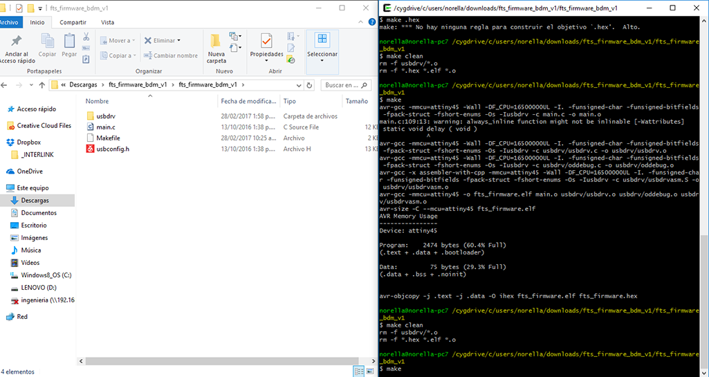
Here i had to repeat some commands to make communication between my computer and the usbtiny (process in images above):
- make clean
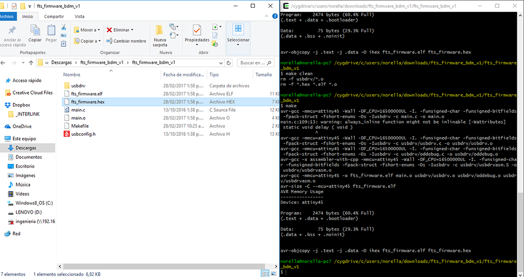
- make
- avr-gcc
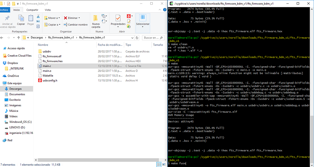
- make fuse
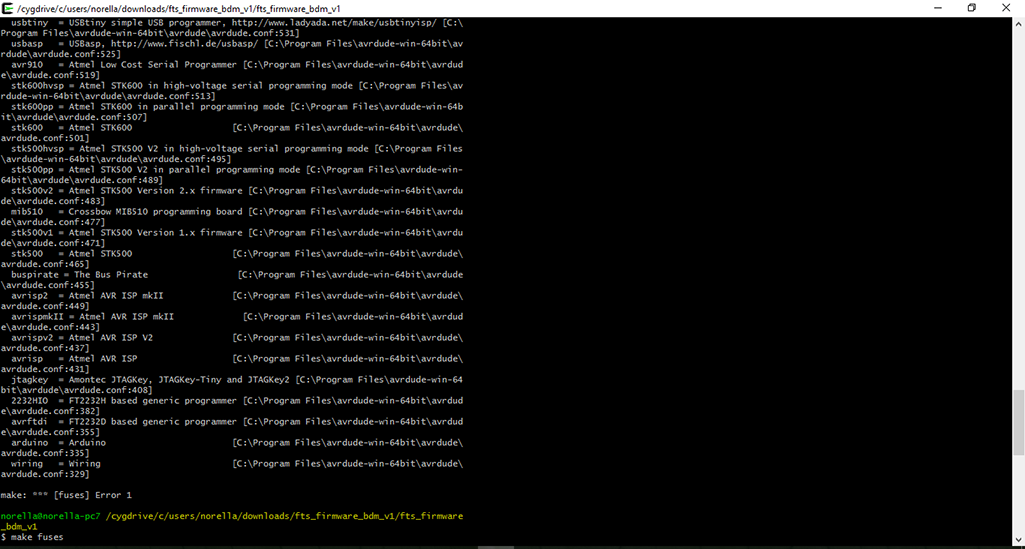
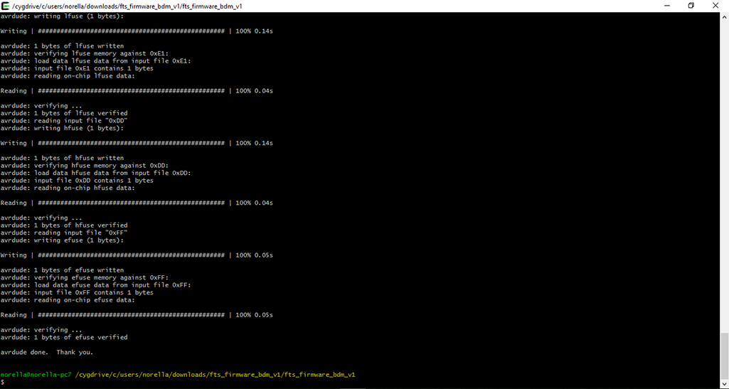
Be careful with spelling cause the command is not -make fuse- but -make fuses- process (images above)
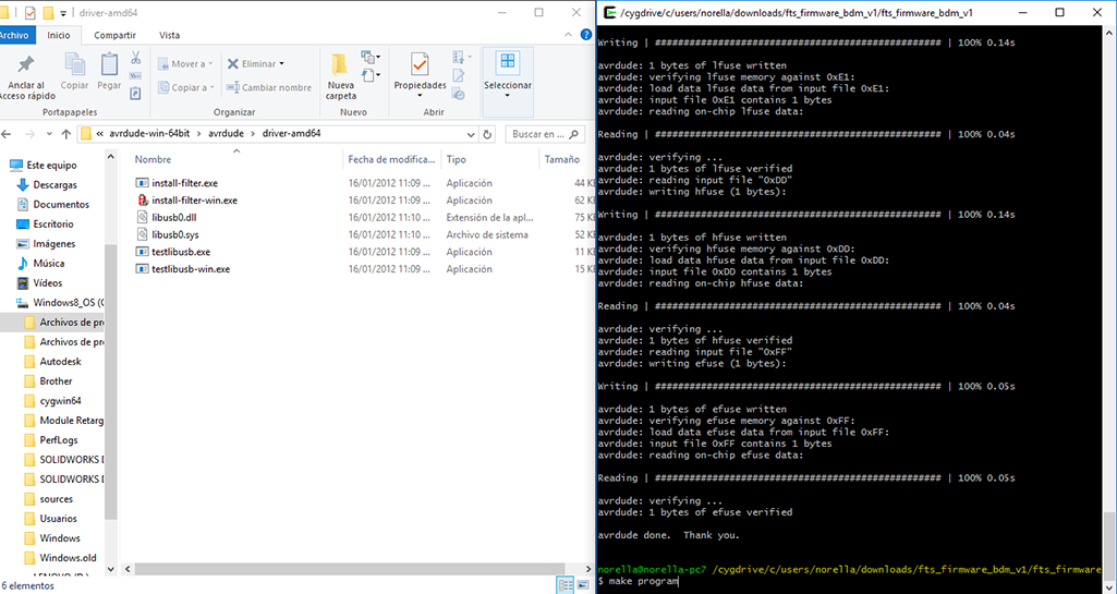
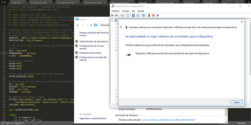
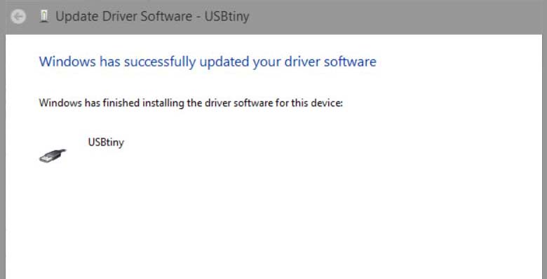
Finally make program and make sure that there is correct communication between your computer and the USBtiny, my first didn't work (images in the center) cause had to unsolder the jumper bridge as Brian Suggested So after that it worked fine. (image at the right)
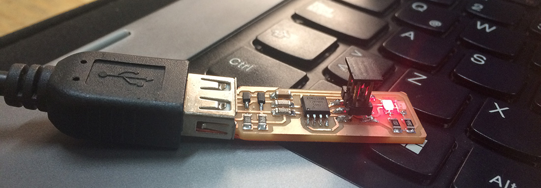
Finally my USBtiny was ready to program other programmers! (image above)
Download Files here:
Electronic Design Bnore Board