Output Devices. Program it to do something.
Assignment
Add an output device to a micro-controller board you've designed and program it to do something
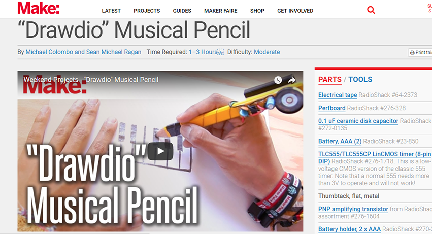
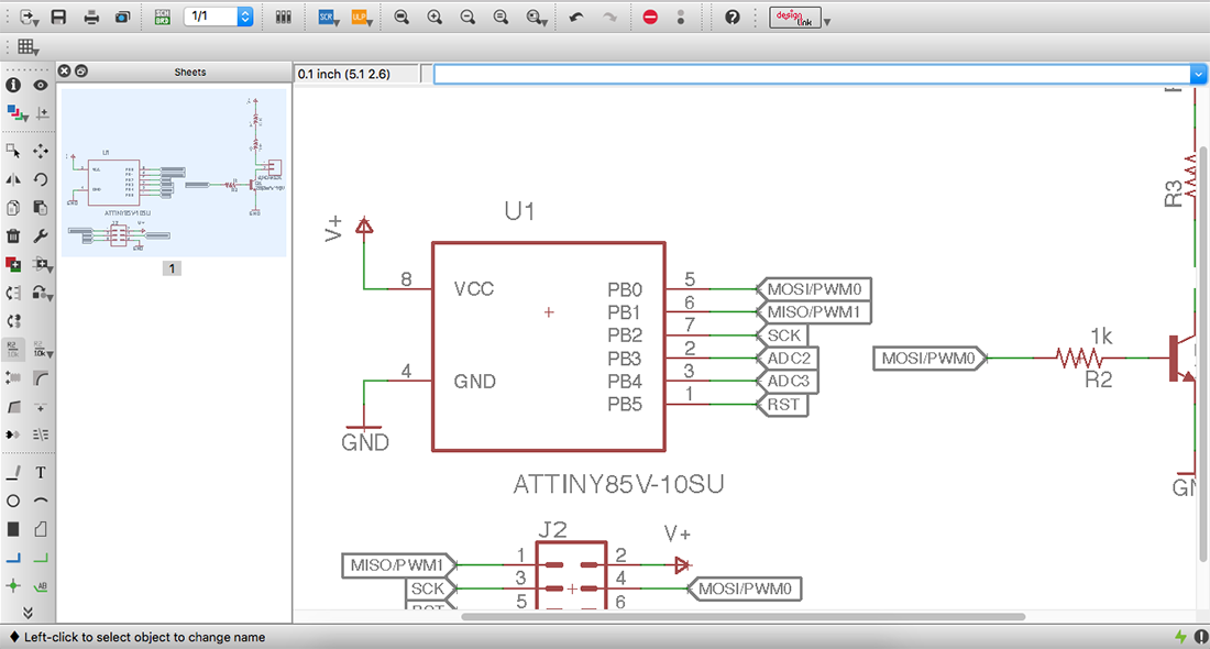
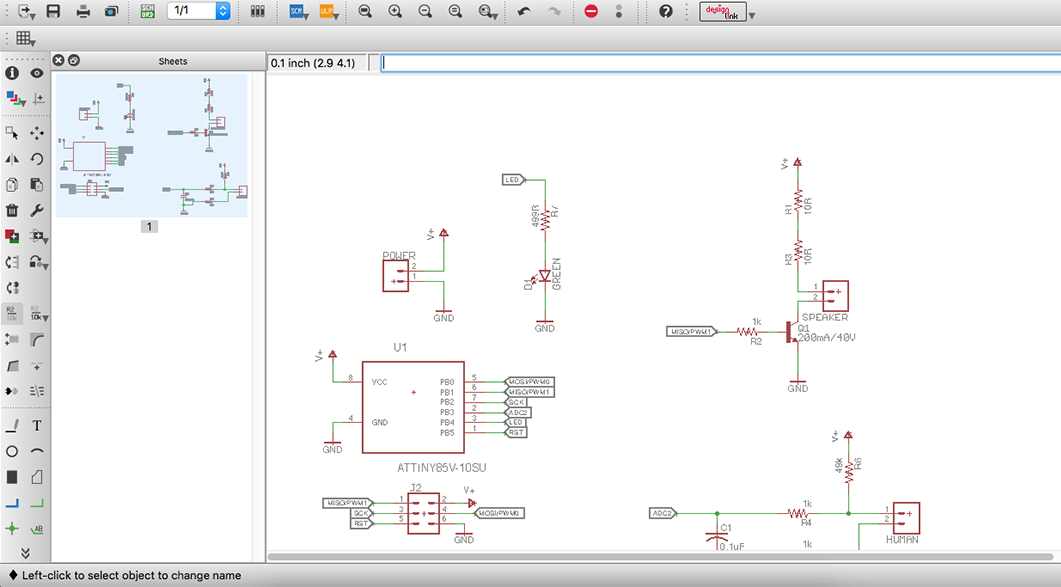
The inspiration for this week assignment was Drawdio musical pencil from the Make Magazine. (image at the left) The first step was to design (image at the right) our board and our main OUTPUT was going to be SOUND, variation in PWM frequency.
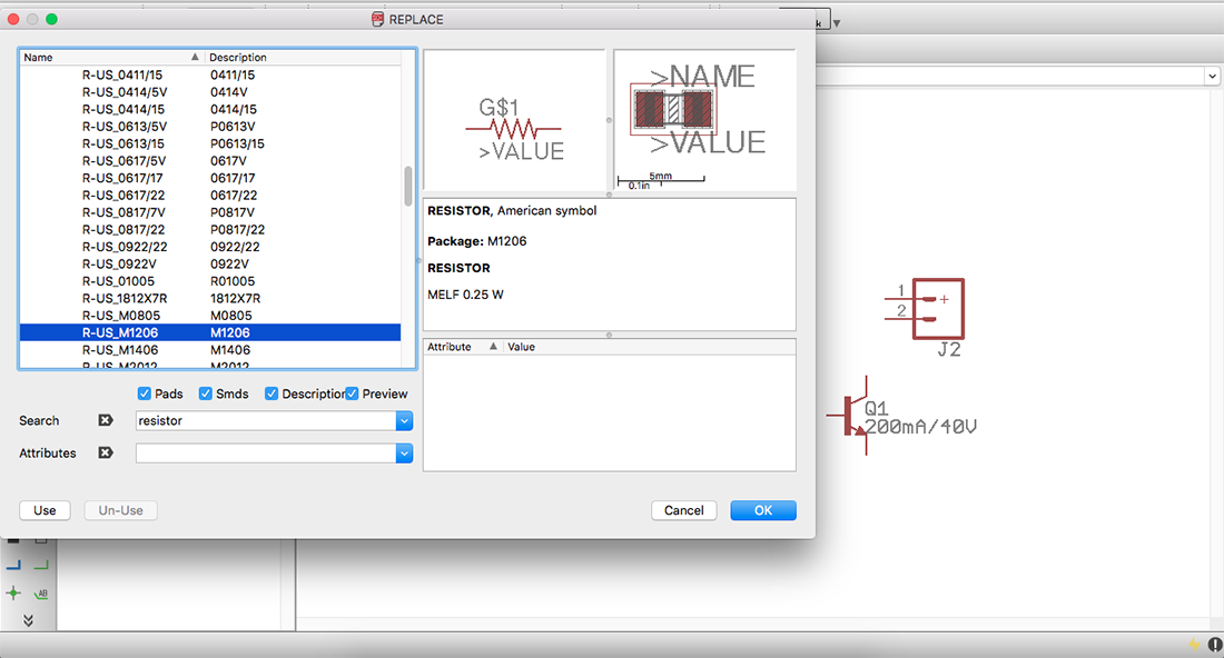
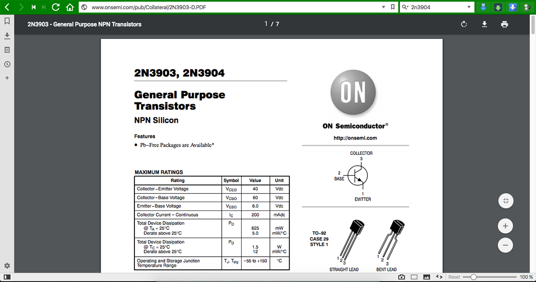
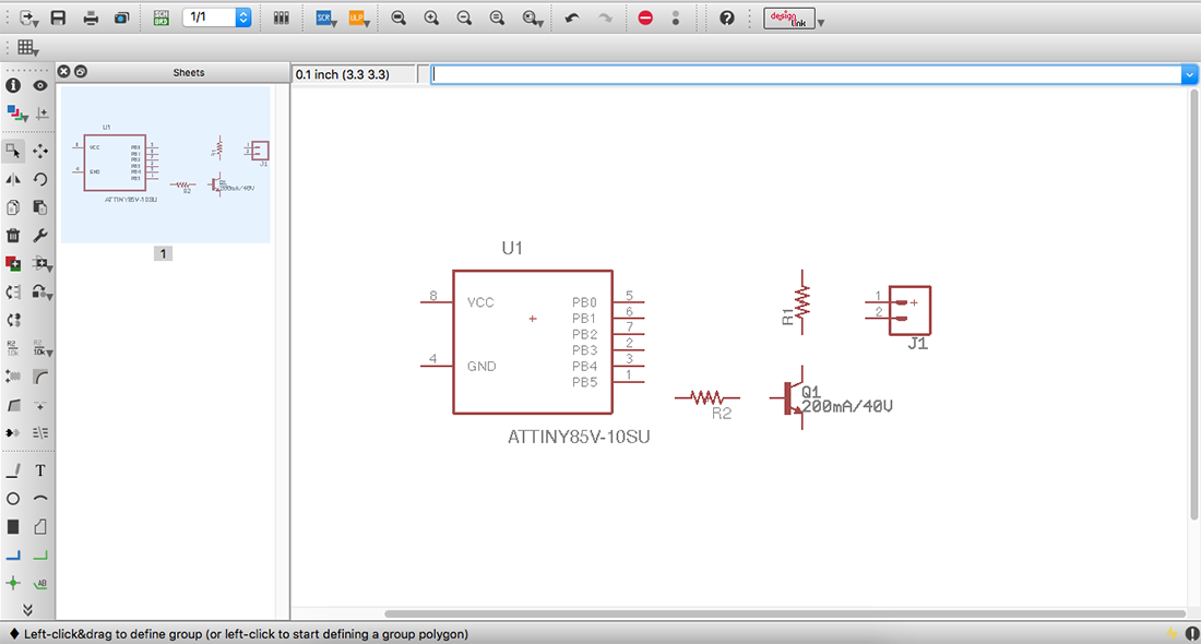
First we started to search for different components that could be usefull in the design (image above show research)
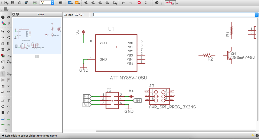
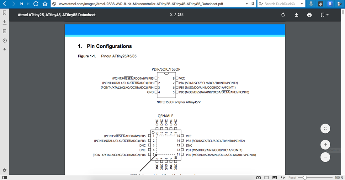
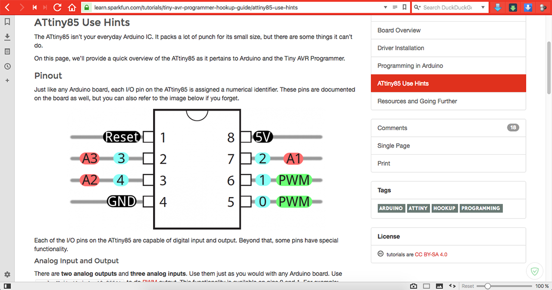
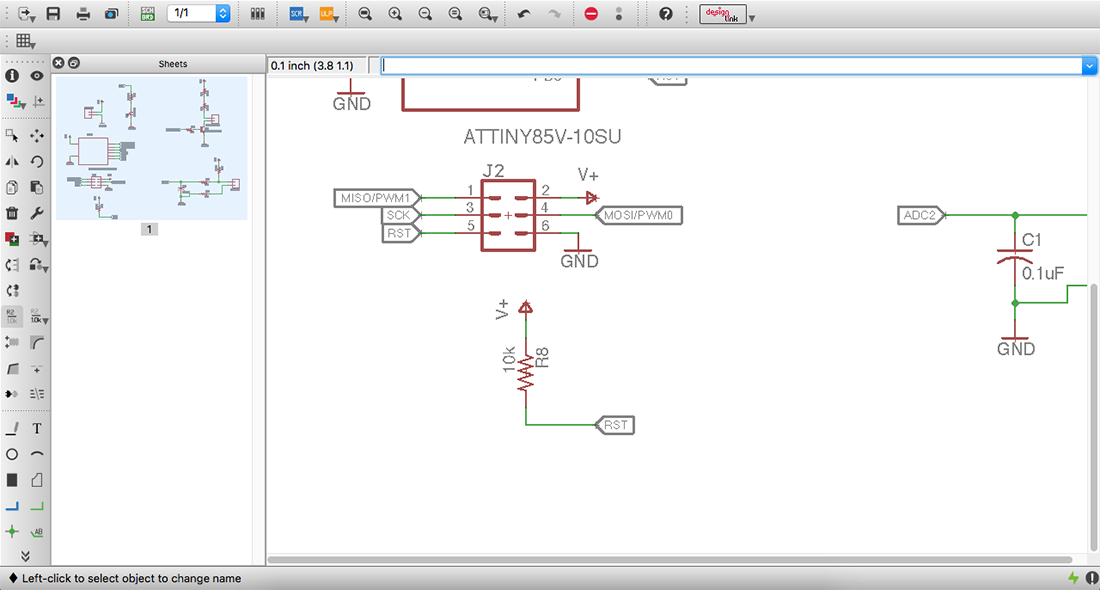
Making use of the Data Sheet of ATtiny 85 to identify how to connect the different components to the mirco-controller.(images above)
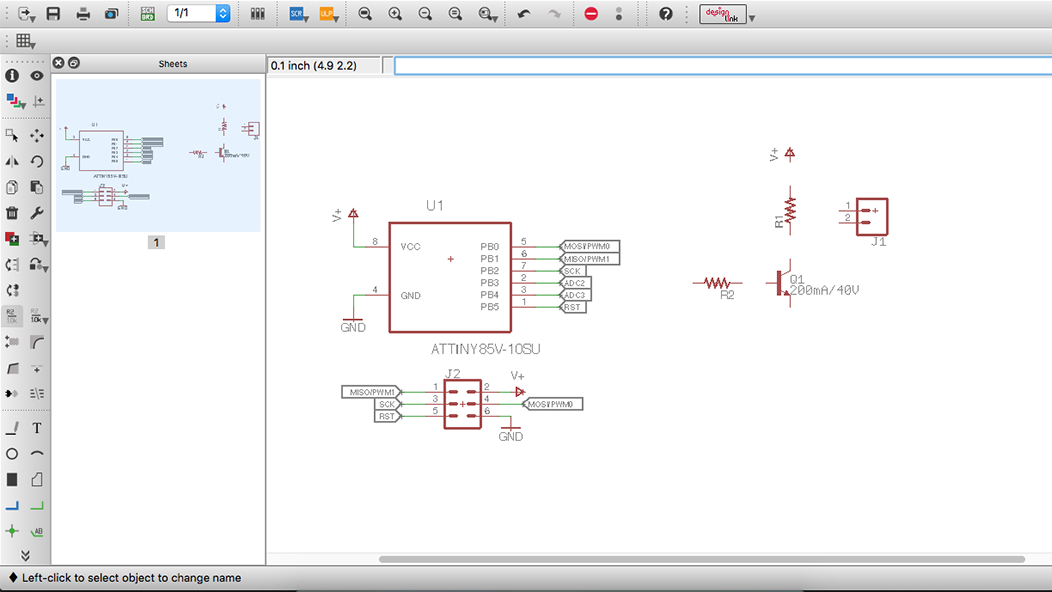
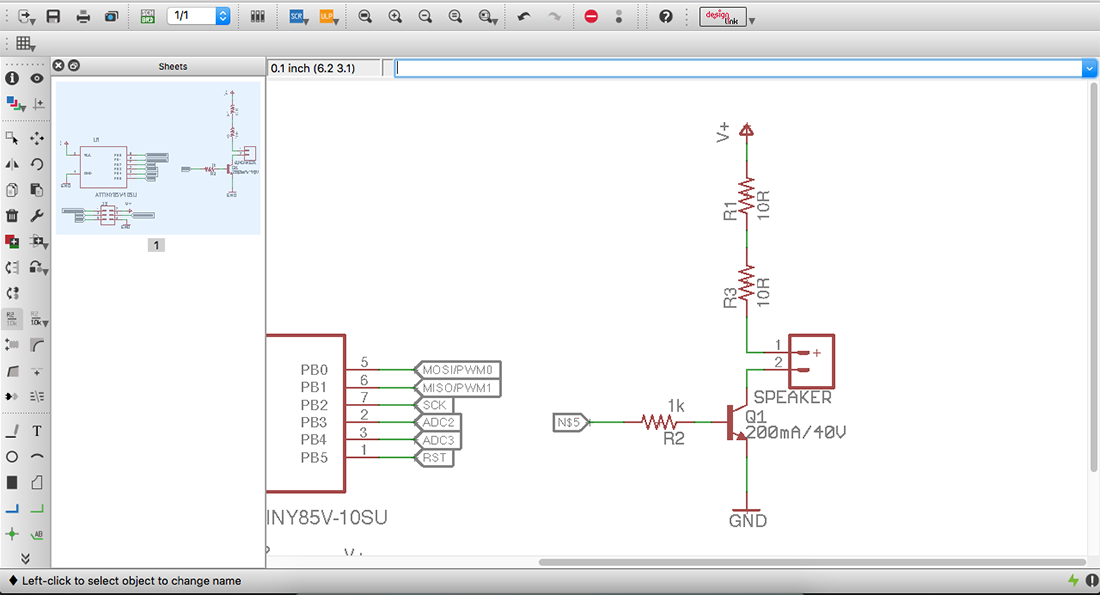
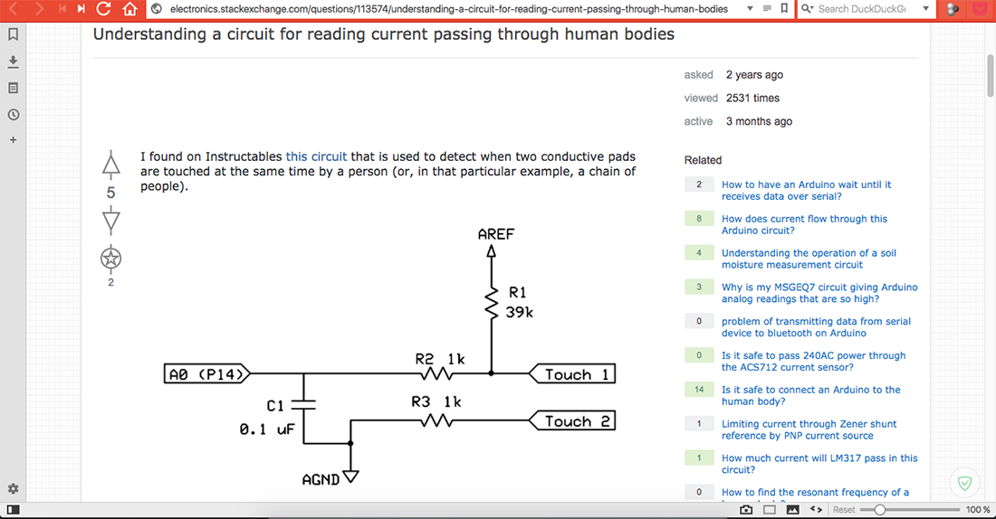
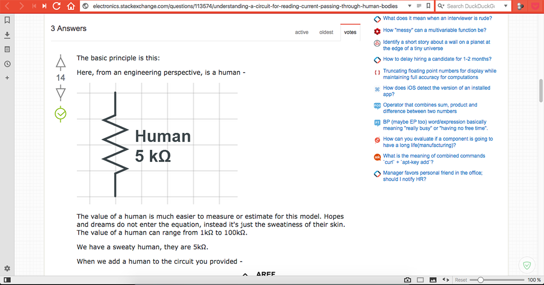
In the images above you can see the process of building and testing with different components, since we wanted to hack the Drawdio by closing the circuit with Human contact
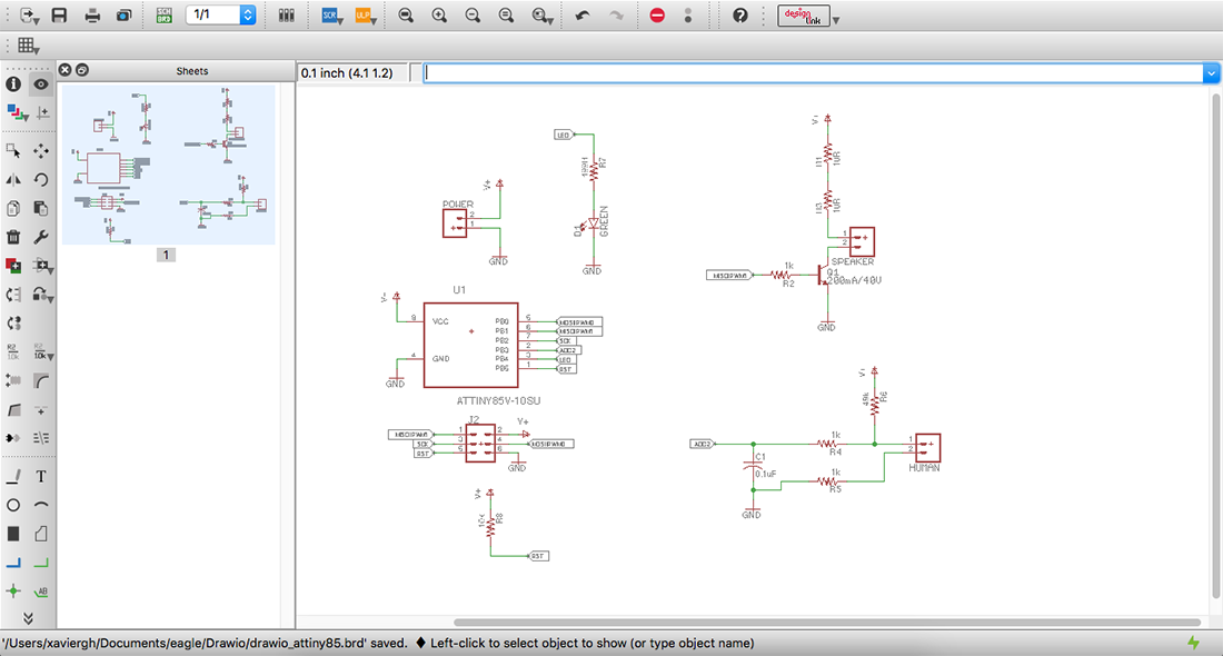
Finishing up the design process (images above)

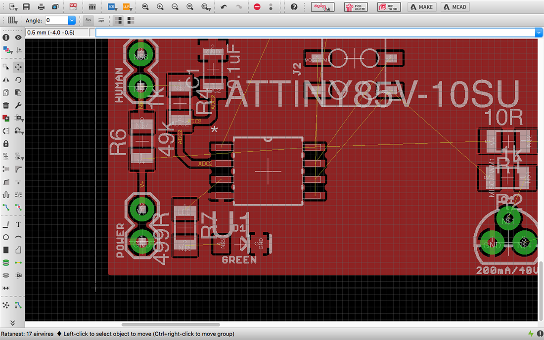
Testing in design skills with eagle (images above)
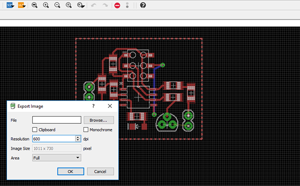
Making some changes using Illustrator (images above)
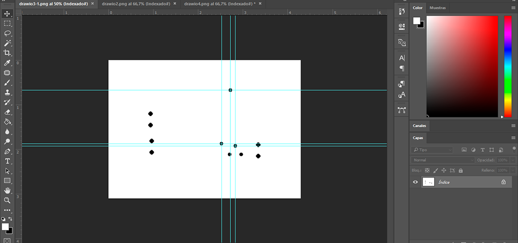
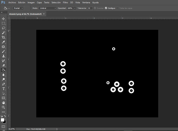
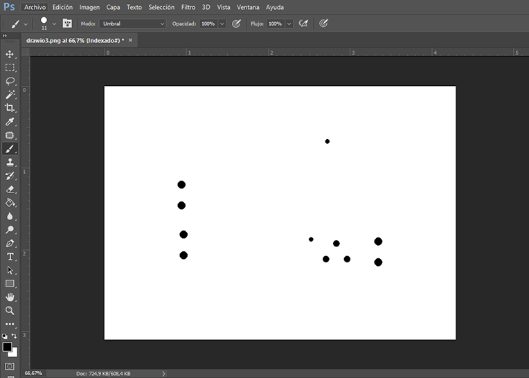
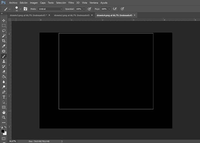
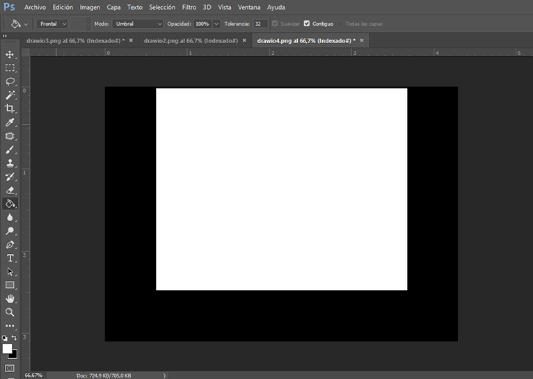
We had some problems with the drilling process so we had to make some changes to the .png file on illustrator, as you can see in images above.
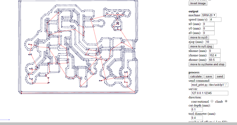
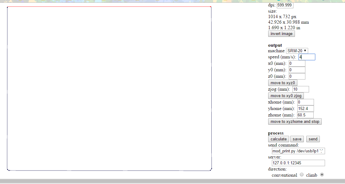
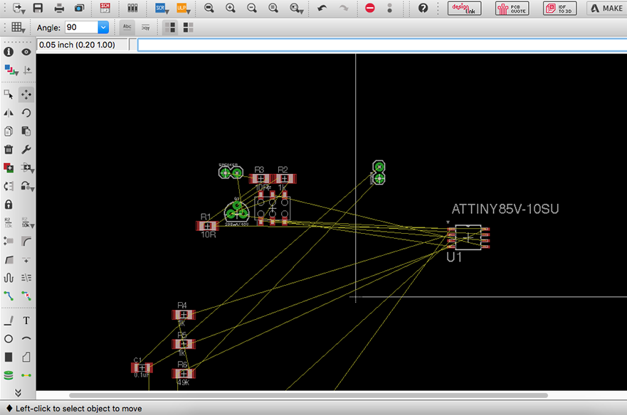
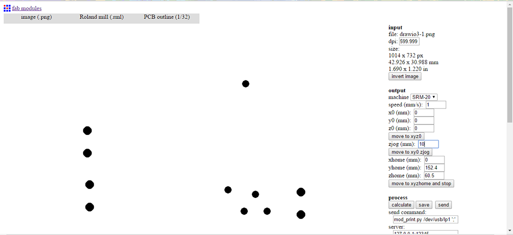
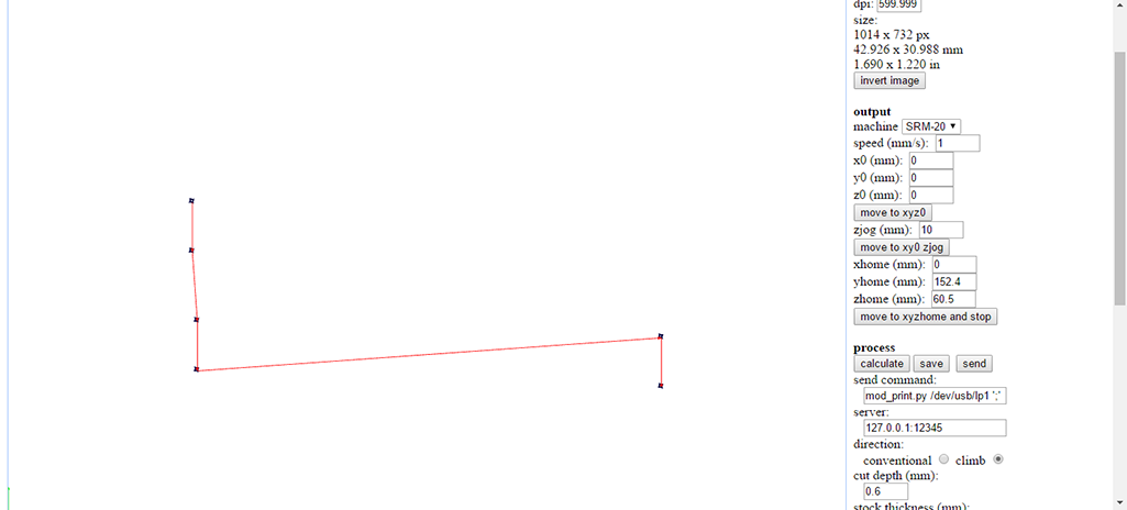
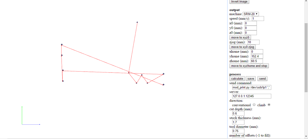
We now have finish setting all the parameters and can start the milling process.
When some traces don't end up the way you plan, some fixing need to be done(video below)
Fix a PCB Trace from Norella Coronell on Vimeo.
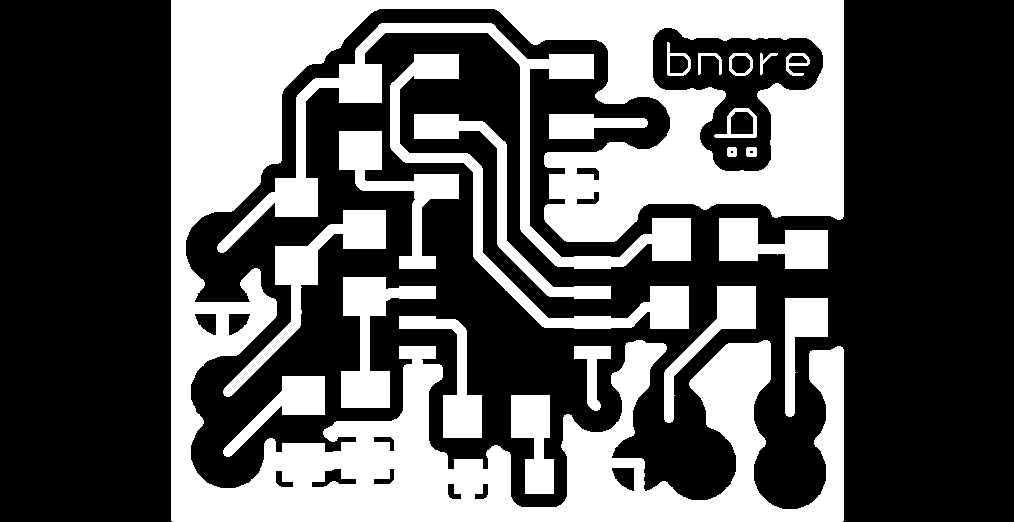
BNORE Board
For it I used the following components:- (1) 1x ATtiny85
- (2) 3x 1kΩ resistors TIP: identify in component as 1001
- (3) 0x 499Ω resistors TIP: identify in component as 4990
- (4) 1x 49Ω resistors TIP: identify in component as 4992
- (5) 0x 3.3v zener diodes
- (6) 1x green LED
- (7) 1x 100nF capacitor
- (8) 1x 2x3 pin header
- (9) 1x 3904 transistor
- (10) 1x Speaker
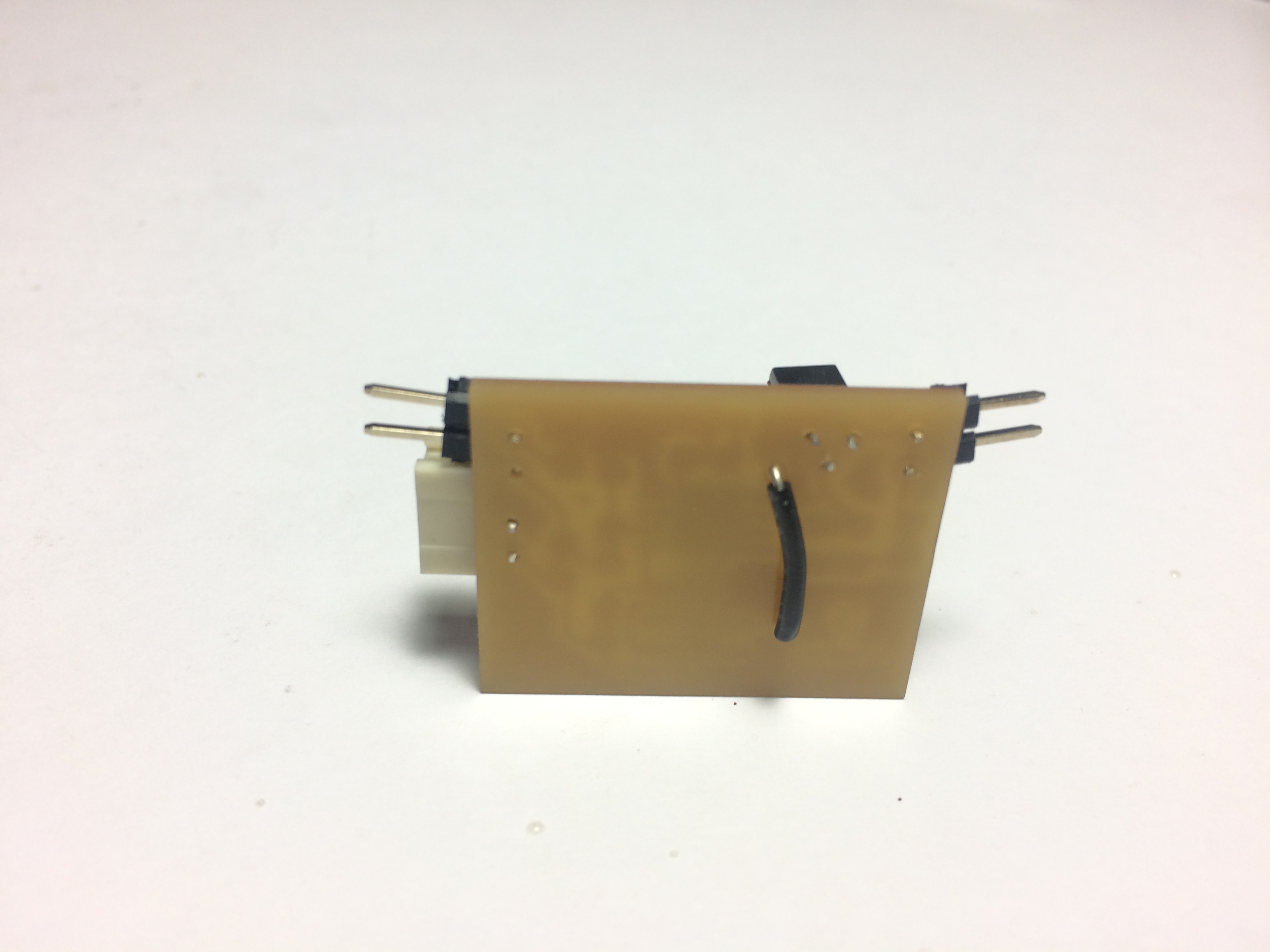
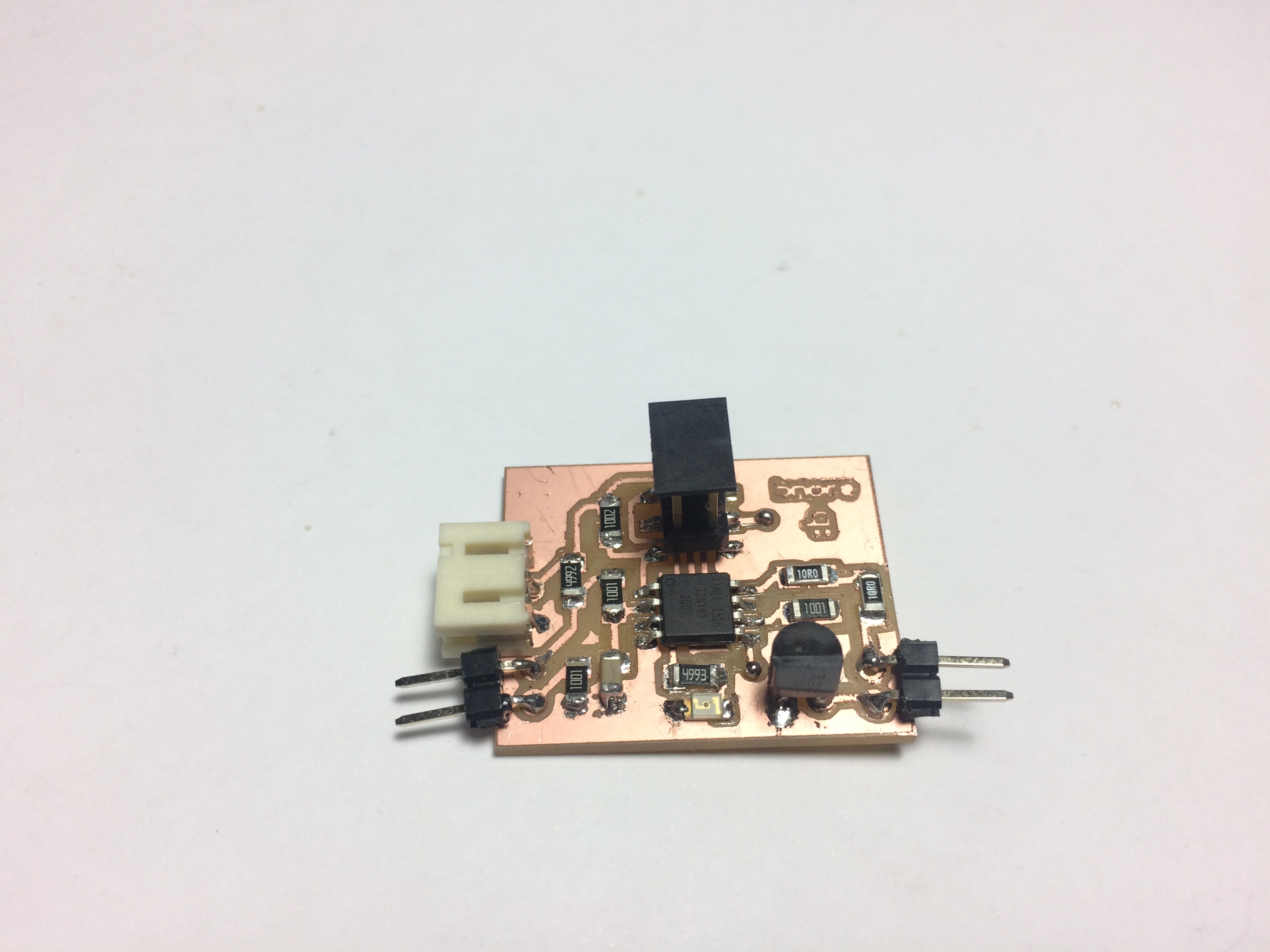
Final Results on the back of the board (images in the left) and on the front of the board (image at the right)
Configurating PWM to create OUTPUT= SOUND(video below)
OUTPUTS on bnore board from Norella Coronell on Vimeo.
Download Files here:
Bnore Evolution