Measure something: add a sensor to a microcontroller board that you have designed and read it.
An input device is a (piece of computer hardware equipment) used to provide data and control signals to an information processing system such as a computer or information appliance. There are many input devices such as :
Temperature Sensor : A temperature sensor is a thermocouple or RTD, that measures the temperature through an electrical signal. It has three pins : VCC , Output & Ground.
Light sensor : A Light Sensor is something that a robot can use to detect the current ambient light level (how dark it is). It has 3 pins VCC , Output & Ground.
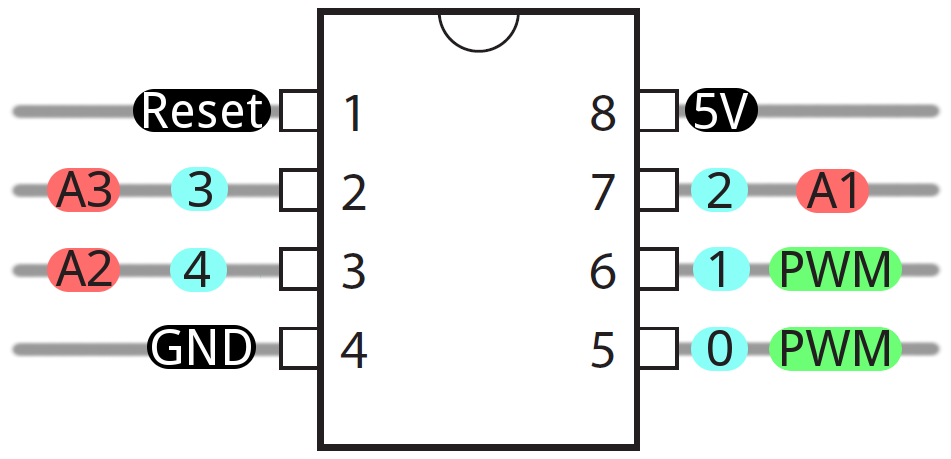
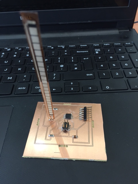
I am using Attiny 45 , I connected in my Flex Sensor to pin PB2 (2).
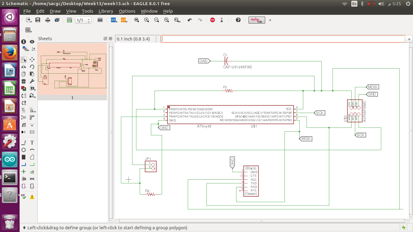
I designed my board and this is the Schematic view of my Flex Sensor board , which I referred from .
In this design I used 5 Volt IC because I’m using a battery power connection.
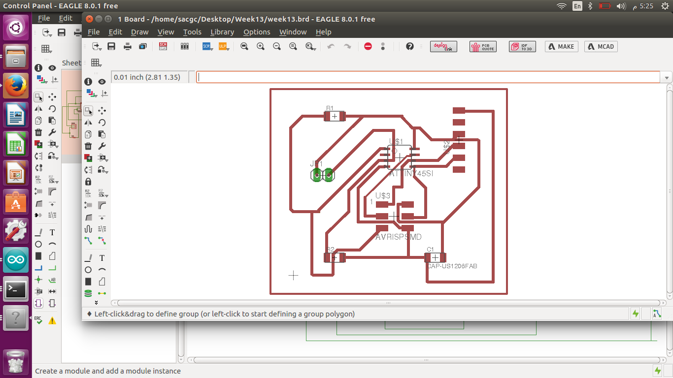
Manual rooting is very complicated thats why I used Auto-rooting , there is some limitations in auto-rooting we cannot get our desired design. When I auto root , some traces are too close to each other.
I move the traces and make some of the traces wider. And increase some of the traces width. To ease my soldering process which is a nightmare to me.
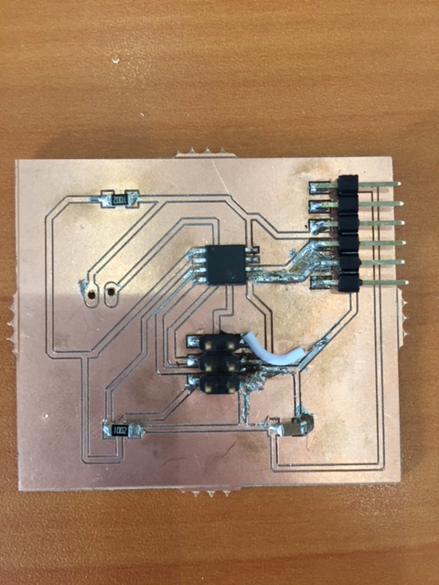
The above board had many shorts after soldering , I made many mistakes while soldering.
So I milled another board and soldered again and programmed it.
Programming :
Below is the code I used to program my board.
#include<SoftwareSerial.h>
SoftwareSerial mySerial (1,0);
int sensorPin = A0; // select the input pin for Flex Sensor
int sensorValue = 4; // variable to store the value coming from the sensor
void setup() {
mySerial.begin(9600); //sets serial port for communication
}
void loop() {
sensorValue = analogRead(sensorPin); // read the value from the sensor
mySerial.println(sensorValue); //prints the values coming from the sensor on the screen