Final Project documentation and presentation
I planned to make the inflatable coin bank with
the shape of Teddy bear. You can see in
my idea sketch which I shown in week
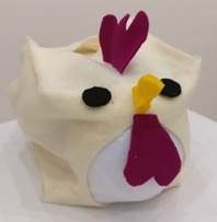
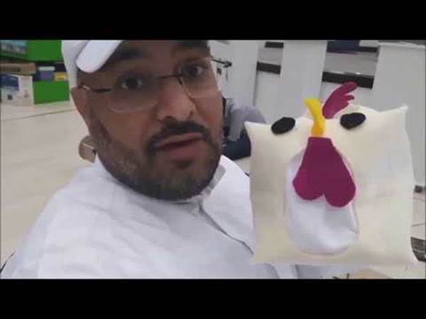
1 page of my website. Later I changed to make the outer appearance of my
prototype as a chicken with it’s belly getting inflates while putting the coin.
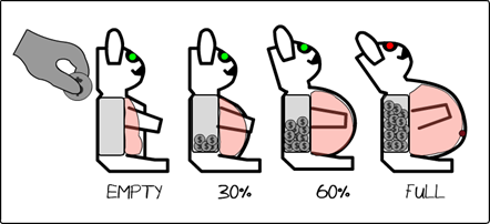
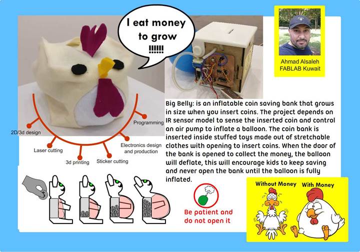
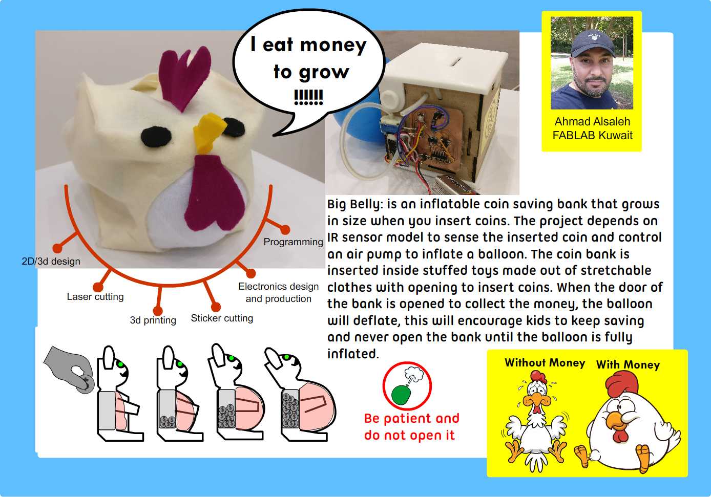
Big Belly: is an inflatable coin saving bank
that grow in size when you insert coins. The project depends on IR sensor model
to sense the inserted coin and control an air pump to inflate a balloon. The
project is inserted inside stuffed toys made out of stretchable clothes with
opening to insert coins. When the bank is opened to collect the money, the
balloon will deflate, this will encourage kids to never open the bank until the
balloon is fully inflated.
Part List/ Bill of materials:
1- Electronics: ATtiny44 , A4953 motor
driver IC,2 X 2 header, 2X3 header,Capacitors(0.1,1 and 10mF),regulator IC (5V)
and 10k ohm resistor
2- IR module
3- 5v micro air pump
4- stretchable for toy pattern
5- Flexible Hose
6- zip ties
Processes used:
1- 2D/3d
design
2- 3d
printing
3- Laser
cutting
4- Vinyl
cutting the logo
5- Electronics
( Inputs/outputs/Schematics/PCB)
6- Embedded
Programming
2D /3D design and Parts created
Main mechanical structures included in my project are created
using following methods.
I used sindoh 3D printer(My personal) to 3d print the
designs. The printed out put quality of the printer is very good as compared to
the one used earlier.
|
part |
Did what
|
processes Tools and machine |
|
T Shape
connector |
Designed +
3D printed |
Fusion 360
+ sindoh 3d printer |
|
Balloon
adapter |
Designed +
3D printed |
Fusion 360
+ sindoh 3d printer |
|
Top cover |
Designed +
3D printed |
Fusion 360 +
sindoh 3d printer |
|
Bottom
Cover |
Designed +
3D printed |
Fusion 360
+ sindoh 3d printer |
|
4 sides
walls |
Designed +
Laser cut |
Fusion 360
+ laser cutter |
|
Coin
extendable slot |
Designed +
3D printed |
Fusion 360
+ sindoh 3d printer |
|
logo |
Designed +
Vinyl cut |
cameo
silhouette |
|
totoro toy
pattern |
Designed +
Laser cut |
Inkscape +
laser cutter |
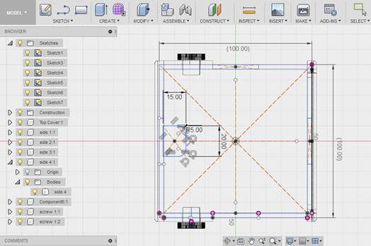
1-2D/3D design(The Bank
Design)
The Main Bank unit is designed to be small to
fit inside a normal Stuffed toy 10x10x10 cm. This time I used vision 360 to 3D
design. Earlier I was using Onshape for my designs. As I want to try new
application, I tried with this and this is different from the web based cad
application.I downloaded the free version of it and started my design.The
speciality which I liked is I can directly 3D print my design and as well as
designing is in offline.
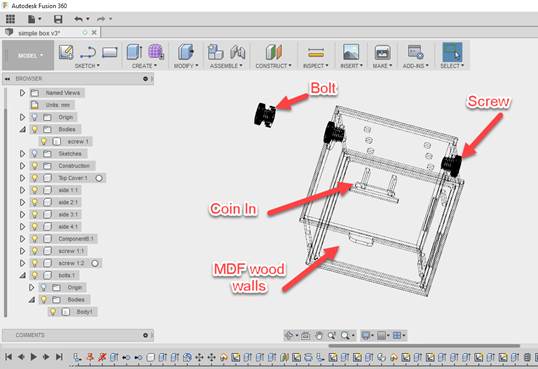
My materials for the side walls and other
mechanical structures are as shown in the above picture.
The design has
4 wood faces that will be cut using 3mm Mdf wood with the Laser Cutter,
top cover and the base will be 3D printed.
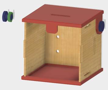
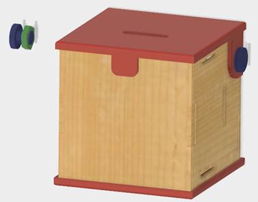
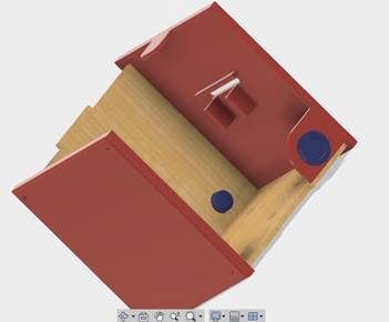
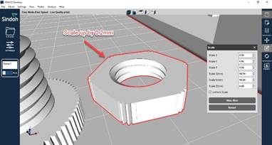
The above shown are the
rendered designs of my container box.Then I designed T shape connector for the
air pump,bolts,air valve,Bottom cover,screw,Coin sliding slot,Top part etc .
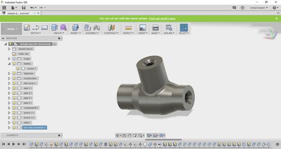
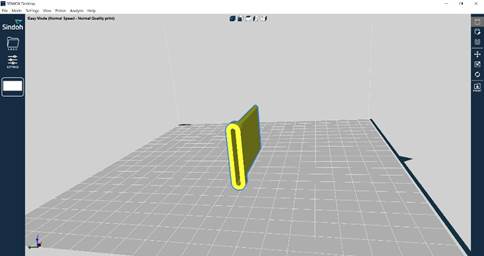
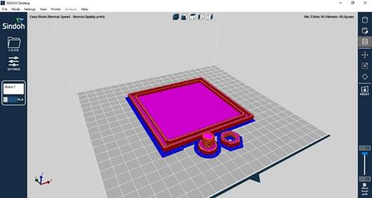
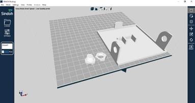
I 3D printed these parts using sindoh printer.I
provided the screen shot of these parts slicing using 3D WOX application for
sindoh 3D printer in below section.Coin slider
is not printed. Because this is a structure for future development option. If
the structure is large. I can fix this over the box.So that Coin can easily
glides through this structure.
2-3D Printing the parts balloon adapter(Air valve) ,T
connector, top part,Bottom part, screws and bolts bottom part etc are done
successfully
Bottom part
Nut and screw
TOP part
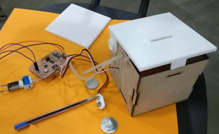
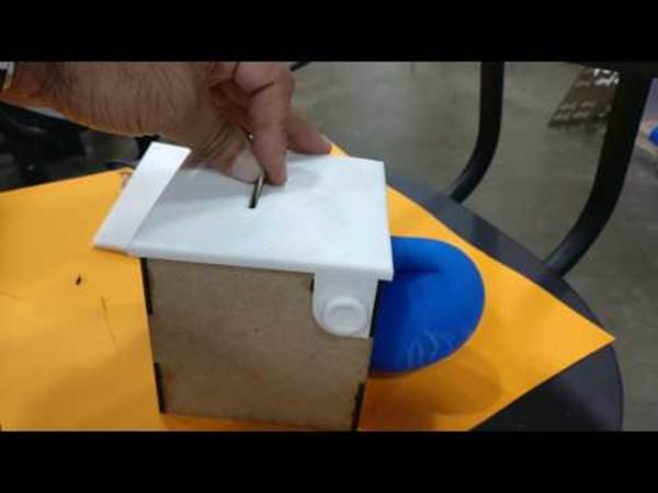
Testing by assembling the parts
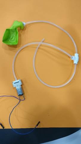
Connecting baloons with pump
I checked the assembly of my printed design,The air valve and other stuffs are tested and it was good enough to fit them well.
3-Laser
Cutting the walls
The side walls of the
container box is to be laser cut. I designed press fit type box with the
required holes and slots and laser cut
the design.
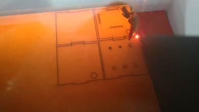
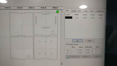
The laser power and speed are adjusted to proper value so that I could get the good ouput.Assembled the box as shown in the image shown earlier.
4-Vinyl Cutting the Logo:
I used Inkscape to design my
logo which can be sticked on my box .I
designed the sticker as shown below.
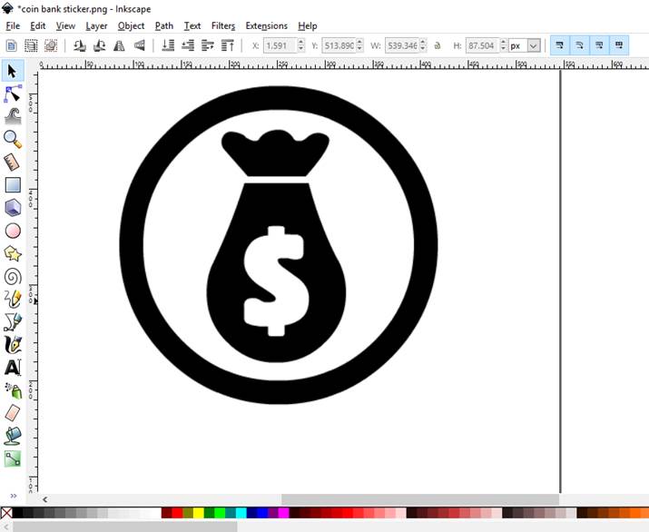
Inkscape designing

Final sticker design
I craeted the PNG file as
shown above using the inkscape..
I loaded the PNG file in to Silhouette cameo Application used for vinyl
cutter.
I got he sticker as per my
design.I used yellow color vinyl for the sticker as material and using the
transfer tape. I pasted the sticker at one side of the box.
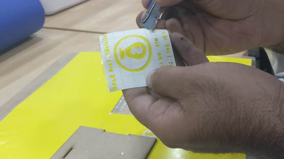
The problem
faced here is that The writings or the Caption I made in the design was unable
to get properly while transfering. You can see the caption in my picture above.
So I Now I
decided to go with out the caption no
5-Electronics
First of all instead of going directly to board ,I choosed to test My Electronic part of my concept.For testing of the idea using the best available electronics prototyping system here, I used EBOT system (For testing ONLY)
https://en.wikipedia.org/wiki/Ebot_(microcontroller).
The IDE for this is simple. Blockly based drag
and drop system which generate Arduino Code automatically corresponding to the
blocks used.
The Board and the project looked like this.
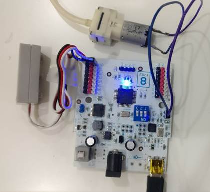
Electronics part testing using E Bot system
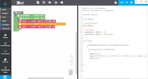
E BOT Application
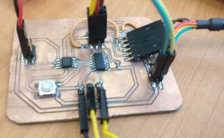
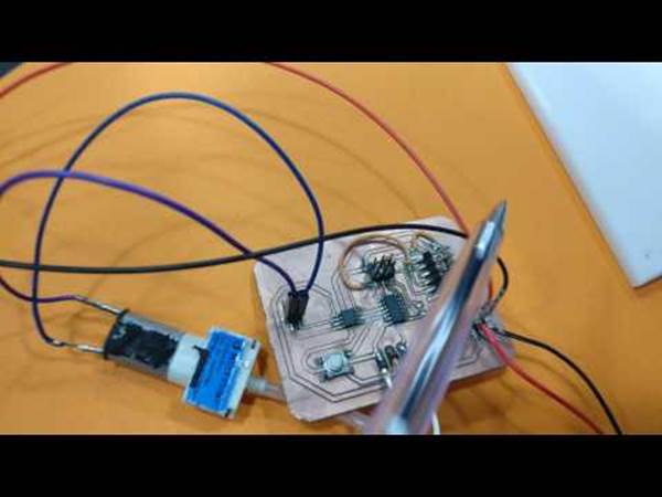
Electronics design:
In the Electronics design process, I already
created a board in the INPUT week.
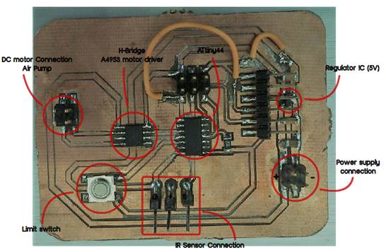
In that there is Power supply connection,5v IC(voltage regulator),IR sensor,
H-Bridge motor driver,Button(Using as limit switch) and 2 x 2 headers for the
DC motor connection.
Here iam
again including the Schematic,Board
screen shots of Eagle design.
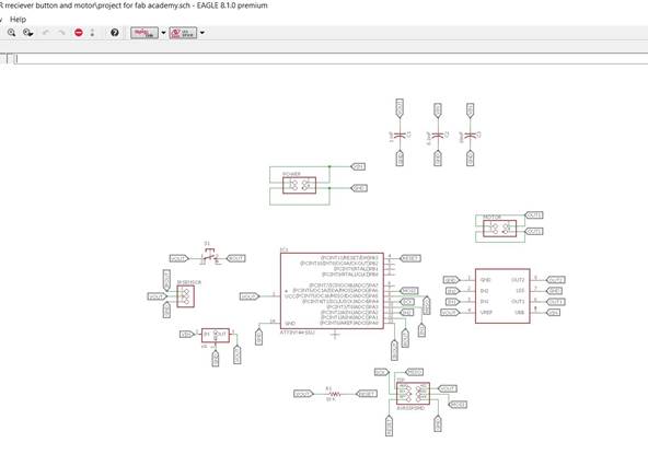
Eagle schematic
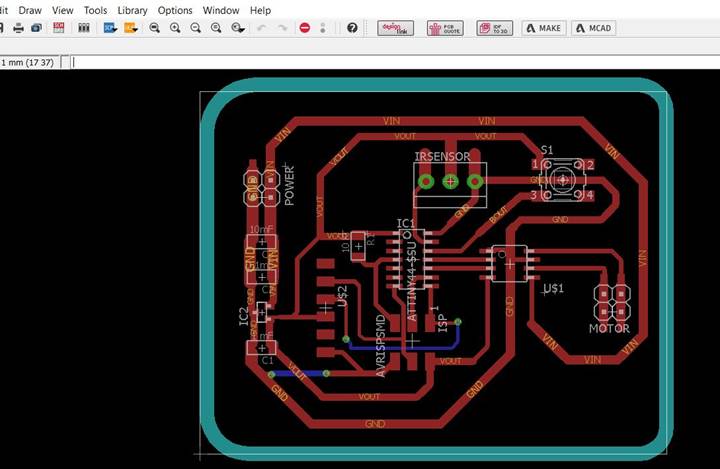
Eagle Board design
Can read the detailed documentation of designing, milling and programming for the
Input process in INPUT week
The main thing
in the input week is the IR sensor. I already got the result of this
board working for input section in this week.
Now the next
is regarding the OUTPUT. I have attached
the PUMP atachment header for the out put and motor cdriver IC in this.AS you
can see, I have done the out put week assignment as a DC motor connected
to A4953 motor driver. I got he output in that week with the proper working of the motor.i
referred the board diagram given in fabacademy archive here .
I added this
motor driver and the output pins (connection headers) and required components
in the design of input board which I can
use for the project.
So now I have
to connect the Air pump which works on the same voltage as that of DC motor.
Please refer for further reading to week 10 -OUTPUT
Devices: Week 10 OUTPUT
Please refer to further reading to week 13 -INPUT Devices: Week 13 INPUT
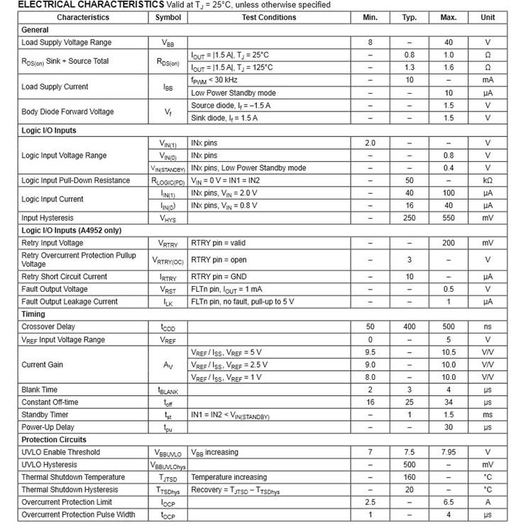
H-bridge Motor driver.
For controlling a DC motror with a Micro
controller, A motor driver is required. Here I am using A 4953 motor driver
IC.
A4953 Designed for pulse width modulated (PWM)
control of DC motors, Allegro's
A4954 is capable of peak output currents to ±2 A and operating voltages to
40 V. Input terminals are provided for use in controlling the speed and
direction of a DC motor with externally applied PWM control signals. Internal
synchronous rectification control circuitry is provided to lower power
dissipation during PWM operation. Internal circuit protection includes
overcurrent protection, motor lead short to ground or supply, thermal shutdown
with hysteresis, undervoltage monitoring of VBB, and
crossovercurrent protection.circuitry is provided to lower power dissipation
during PWM operation. Internal circuit protection includes overcurrent
protection, motor lead short to ground or supply, thermal shutdown with hysteresis,
undervoltage monitoring of VBB, and crossovercurrent protection.
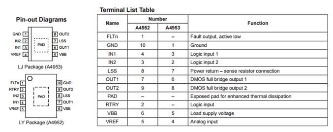
The A4953 is
provided in a low-profile 8-pin.
|
Features |
||
|
|
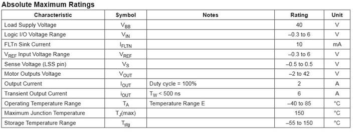
Datasheet for the A4953 is here
Reference: Digikey
Some important datas and ratings I referred
from the datasheet:
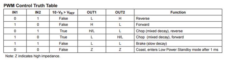
To Control the
airpump used for this, I used the
following logic table.
For the supply voltage to the board, I used 9V
battery.
IR sensor:
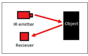
IR transmitter and reciever
IR transmitters and receivers
are present in many different devices, though they are most commonly
found in consumer electronics. The way this technology works is that one
component flashes an infrared light in a particular pattern, which
another component can pick up and translate into an instruction. These
transmitters and receivers are found in remote controls and all different
types of devices, such as televisions and dvd players. Peripheral devices
that include this technology can also allow a computer to control various
other consumer electronics. Since infrared remotes are limited to line of
sight operation, some products can be used to extend the signals over a
hardwired line transmissions.
Most common consumer electronic remote controls use
infrared light. They typically generate infrared using light emitting
diodes (LEDs), and the main component of a receiver unit is usually a
photodiode. A remote control flashes a pattern of invisible light, which
is picked up and then turned into an instruction by the receiver module.
The parts necessary to construct transmitter and receivers are typically
inexpensive, but these systems are limited to line of sight operation.The
detailed
6-Embedded Programming
Using the A4953 logic tables and other
conditions to work my pump, I Created a code in arduino IDE that look like this.
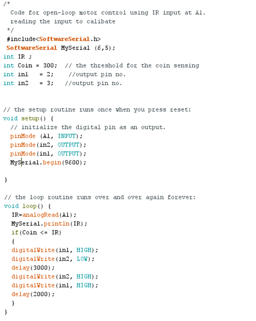
I used serial print commnad to print the IR
value so that I can detect whether coin is sensing properly or not.
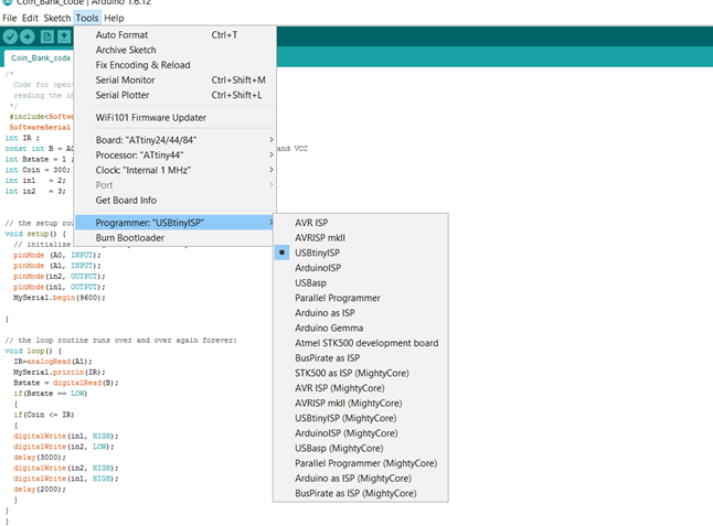
I downloaded in the board by configuring the
Attiny controller and Tiny USB as programmer in Arduino IDE.
IR sensor calibration:
I used serial command with Arduino IDE terminal
and connected FTDI cable to check whether IR readings are proper or not.
Extra activities,Problems and
Future modifications :
- Used glue gun to prevent air leakage
- Problem sensing the falling coin because of
the falling speed.
- The cube size issue, it’s much better if it
were cylindrical
- The balloon inflation mechanism should be
better
- Need to add coin slider path if Large size
shape is using for outer covering.
Poster, Presentation
video,Testing and progress videos
Poster:
Video 1:
Video 2:
Presentation video
My presentation video file is here
Finally I done my project
which was only a concept for me and I was
dreaming about how I can achieve it atleast by making a Prototype.
I Thanks firstly
Almighty and then My instructors,Collegues
and Also FAB LAB and Fab Academy system to achieve this from bottom of my
heart.
Files:
3D design of box in fusion 360 : http://a360.co/2sijSlz
Air valve:air
valve stl file
Bolts: BoltsSTL file
Bottom cover:Bottom cover STL file
Screw 3d print:Screw.stl
Top part 3D print:Top
STL file
Two way connector valve:Two
way connector
Chicken character Shape design:Chicken
design
Vinyl cutter sticker design:Sticker file
Sticker PNG file for vinyl cutter: Sticker.png
Poster File:Poster.jpg