Week 12
Input devices
In this week,I want to make a PCB for input.With that i have to read or measure using sensor.
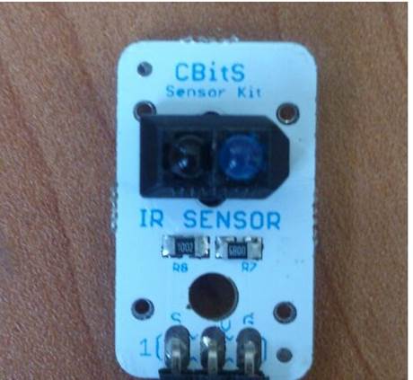
I am using IR (Infra Red) transmit receive sensor as the input device.
IR Sensor work by using a specific light sensor to detect a select light wavelength in Infra-Red (IR) spectrum. By using an LED which produces light at the same wavelength as what the sensor is looking for, you can look at the intensity of the received light. When an object is close to the sensor, the light from the LED bounces off the object and into the light sensor.
Image from here
I went through following steps:
1 - PCB designing.
2 - PCB milling.
3 - Soldering the components.
4 - Programming .
5 - checking the output.
PCB designing:
I modified the output week design(neil’s DC motor board ) and added IR sensor attaching headers,FTDI cable attaching headers.
I made the connection to PA0 pin for IR sensor signal.There is 3 Pins for IR sensor module. Signal,VCC and ground.(S V and G)
I added FTDI as well to the design.I connected Transmit and receive pins of FTDi to the MISO
And MOSI respectively.
I generated the corresponding board file in eagle and gave an outline to cut.
PCB milling:
Then i generated .cmp file after CAM processing in eagle. Using cirQwizard,I converted my design into machine code and milled the board.
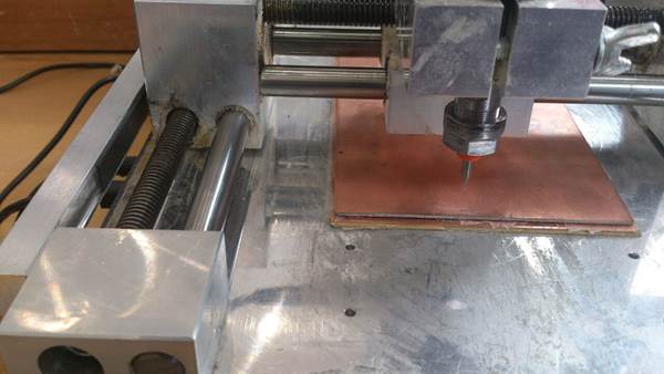
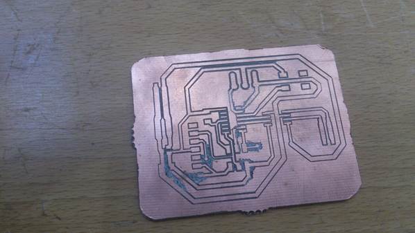
I got my board milled as per design.
But during milling the board was not level. I changed the z axis position many times to get milled in every location in my design. I cleaned the board well.
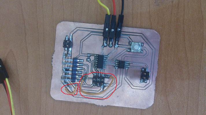
Soldering the components
I arranged the components in a paper with double side tape. I checked every time with the multimeter for continuity of connection after each component is soldered. I cleaned the separation between the traces to avoid short circuit connections.
I soldered the components in their respective positions in the board.I connected vertical header for the IR sensor pin and also for FTDI (for serial data communication through RX and TX.
In my board, I made two connections in bottom layers. For connecting that,I used jumper wires to connect in between them.
Programming
In programming, Firstly i have to burn bootloader. I have arduino IDE and the ATtiny library already installed in arduino IDE .
I checked VCC and RESET pins in ISP programming header of my board.I connected corresponding pins to the USBtiny programmer.
I connected ISP programmer to PC and my board.By opening the Arduino IDE and selected the board,processor and programmer.
Selection of board,processor and programmer are selected as ATtiny24/44/84 , ATtiny44 and USBTinyISP respectively.
Bootloader is burned as:
tools menu> burn bootloader.
My bootloader is burned successfully.
Now i have to connect My input module to the board and as wellas FTDI to the board
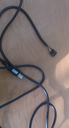
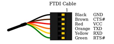
FTDI cable.
I checked the Pin configuration and connection to VCC, ground,RX and TX pins respectively before connecting to board by using the below configuration.
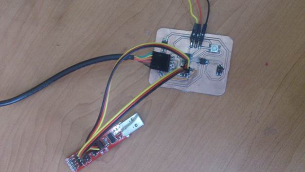
I connected FTDI to my board.
Since i connected MISO and MOSI pins of micro controller for RXD and TXD of FTDI, I cross checked the arduino pin numbers of MISO and MOSI of ATtiny44 for programming. It was number 5 and 6. I used the pin configuration diagram below for reference
PIN Config diagram for ATtiny
Image from : here
Using the example program available for software serial Arduino , I changed the pin number corresponding to my configuration.
I connected IR sensor and then added commands for IR sensor value reading using analogRead() command. I have connected the IR sensor to A0 pin of arduino for Attiny.
I uploaded the following program for my board.
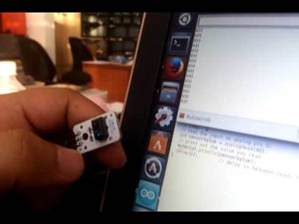
checking the output:
After uploading the program i opened the serial monitor of Arduino IDE and my sensor is detecting the objects in the front. I can see the values changing if any objects are coming in front of Sensor.
The video of output is :
Files:
Eagle circuit design schematic:eagle schematic
Eagle circuit design board file:Eagle Board
.cmp file for Cirqoid machine:.cmp file for machine
Arduino code file :Code