Week #20 PROJECT
Assignment
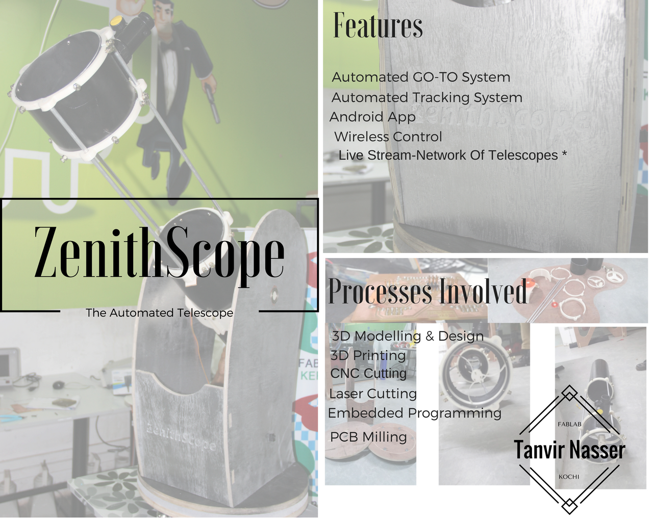
ZenithScope
ZenithScope, is an automated Android App controlled GO-TO telescope, that also tracks the selected celestial body throught the night.The telescope would be controlled wirelessly(Bluetooth for now), a repository of some celestial bodies would be stored in the app, also custom coordinates can also be given.This project is envisioned to bring about the citizen era of space explorers. I believe, that by eliminating the requirment for knowing the position of various celestial bodies for manually aligning the telescope and viewing, it empowers enthusists, hobbyists, and students.Also, having the live stream of the celestial body, accesbile through an online portal, this project aims to build a community of innerconected astronemers that arent limited by the location where they are.The telescope features a 6 inch primary mirror, capable of viewing quite a lot of planets in our solar system and various star clusters.
A rough prototype of the GO-TO system was demonstrated in our lab group project, where we build an approximate system to find the celestial body of choice.Here, in the final project we aim to refine it and add more features, and have it as very good final product.As the GO-TO system,Tracking System,Android App Development, Drive Systems, and the physical mounts are quite a vast topics to cover in a short span of time, this project has been done by a team of 2, consisting of me and Suhail.
Work to be done
As the final project has to showcase that individually we have worked on every process, and given the time could do the work independently.The complete work to be done has been splitted so that each of us has work to be be done individually on all the machines and processes.
| Process | Tanvir | Suhail |
| 3D Design | YES | YES | 3D Printing | YES | YES |
| Electronics Productions | YES | YES |
| Embedded Programming | YES | YES |
| CNC Cutting | YES | YES |
| Laser Cutting | YES | YES |
With regards to the 3D design and 3D printing exercises, I would be doing the design and printing of the laser holder, primary mirror holder, the clamp for the optica tube, and guide rings for the the aluminium rods.
In the electronics production department, I would design, mill and stuff a PCB which would be used for motor control, LCD display, and homing switch.
In the programming field, I would be involved in developing the code for finding the celestial body, given its Right Ascension and Declination,and also developing the code for tracking it throught the night.
I would be also be designing and cutting the base of the telescope in Shopbot, by calculating the position for mounting the motors.
The gear design and laser cutting would also be done by me.
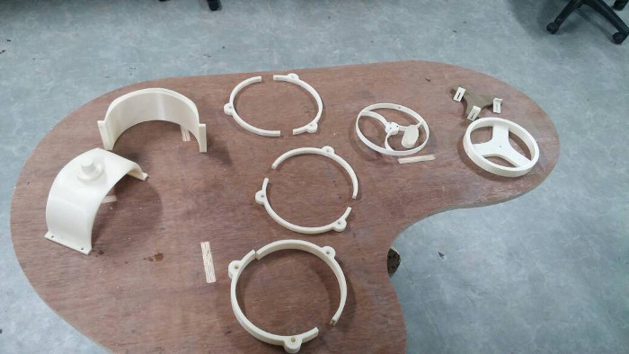
3D Design and 3D Prints
Primary Mirror Mounts
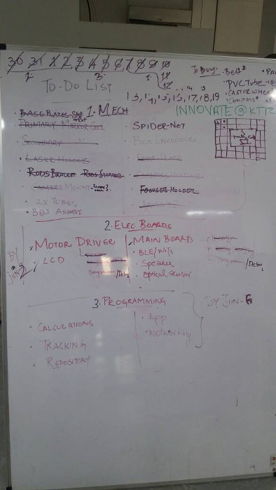
To get started , I decided to create an adjustale mount for the 6" primary mirror.For this I designed a two piece mount in Onshape.
The mount is designed such that by tightening the nuts at the bottom of the mount, the mirror can be adjusted around its centre point.THis would be helpful when fixing the focal point later on.
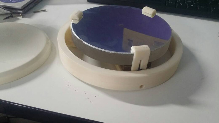
The above piece would be placed right below the mirror with the nuts being inserted in the holes on the top staying flush with the surface.
The above piece would be flanked by mirror clips on its 3 ends to prevent the mirror from falling over, an adjustable slot is given to tighten the clip as required.
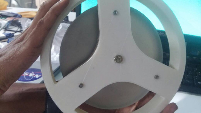
This set would be mounted over another circular frame which would be attached to the Optical tube.
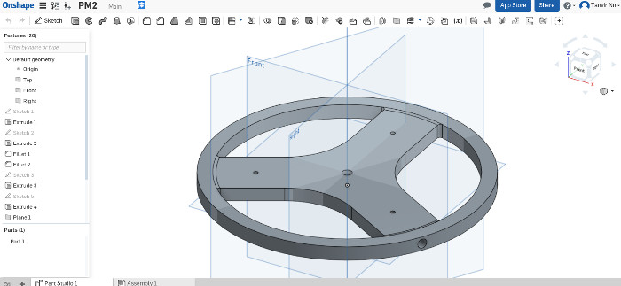
Once assembled the primary mount assembly would like this:
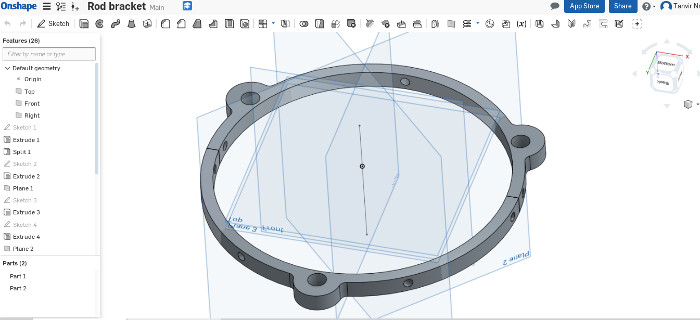
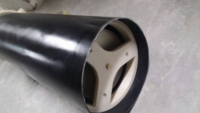
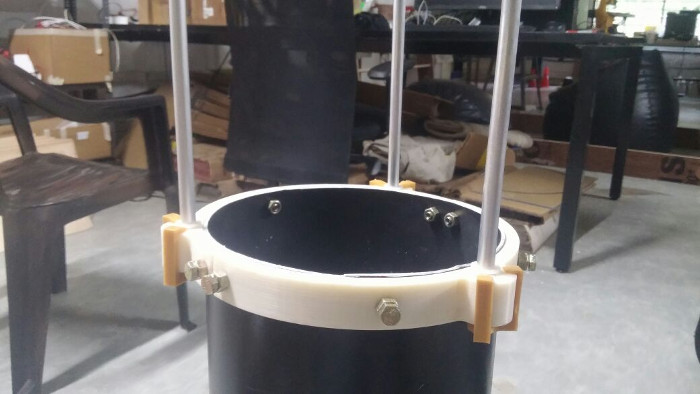
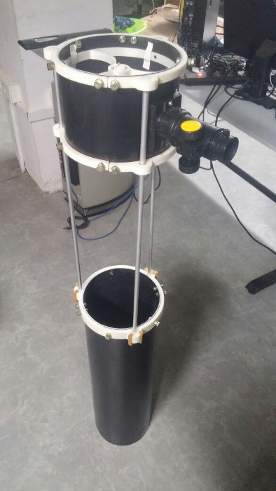
Guide Rings
Aluminium rods are used in between two pices of PVC tubes, so that the assembly can be collapsible when not in use. So a set of guide rings had to be designed for the rods to move.
The rings were designed so that three rings at an angle of 120 degrees to each other.
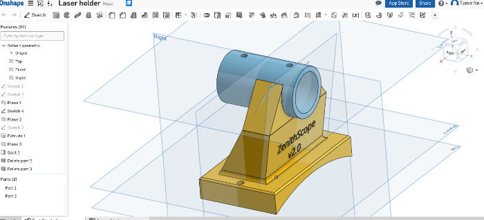
Laser Holder
To use as a line pointer, a laser would be clamped onto the Optical tube Assembly(OTA), this too has been designed and 3D Printed.
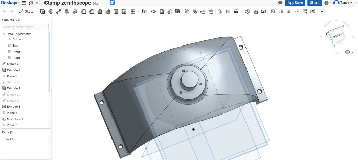
Optical Tube Clamps
The whole assembly of the tube, mounts,mirrors, and focuser needs to be rotated along the altitude, for this a clamp had to be designed that fits over the tubeand runs through a bearing between the two side arms.
The part was designed in Onshape, and printed in Dimension 1200 es.
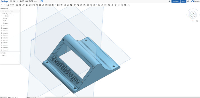
LCD Holder
The LCD has to be mounted on the base at an angle comfortable for viewing from the top. This factor along with the constraint of hieght of the box enclosure housing the PCB, led me to separate the LCD from the box enclosure and display it elsewhere.For this I designed a LCD mount in OnShape.
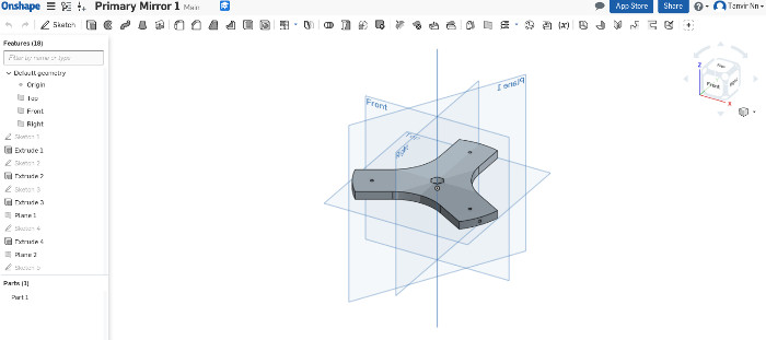
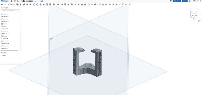
Rod Clip
The Optical Tube Assembly (OTA), is built to be a collapsible , so that it can be easily carried around.For this, when completely opened up, there needs to be a rod clips to keep the secondary part of the OTA in place, for this I designed a clip,that would latch on to the guide ring.
2D Design and CNC Cutting
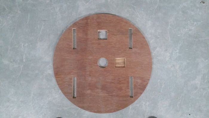
The base upon which the whole telescope assembly would rest would be designed and CNC by me.
The crucial design part here is to find out where to place the depressions for the motors.As a closed loop belt drive system is used to drive the base, it is essential to know the distance of the motor spindle from the centre of the base upon which a reduction gear would be mounted.
To find this out I used a formulae , that I used back in school.
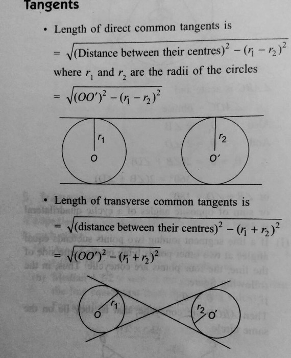
This gave me the distance between the two centres , when using a 400mm closed loop GT2 belt
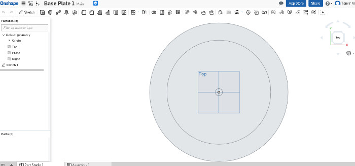
I then drew a 2D DXF, in Onshape to have it CNC cut.
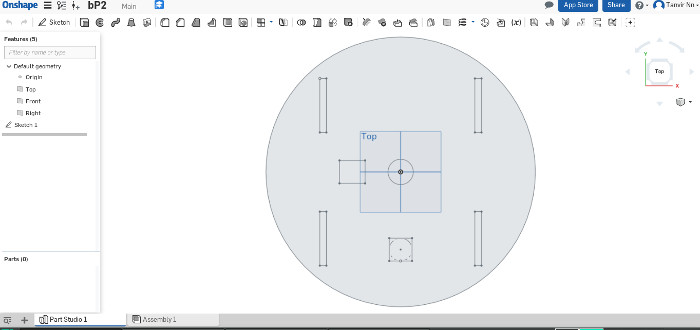
The motors were given a 15 mm pit were they would be inserted.The base was cut in 18mm plywood.
The base that has been designed and cut above, would be resting on another set of stationary base, rolling over a set of castor wheels.
Laser Cutting
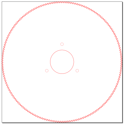
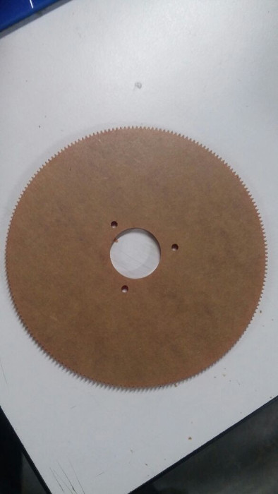
The drive system in the telescope is a belt system.For this I designed reduction gears so that the overall movement would be smoother and much finer resolution can be achieved.Moreover, the torque required would also decrease.
The pulley I had for the GT2 timing belts had a 20 tooth, 12.7 pitch diameter. A simple method to make gears is on GearGenerator.com
The gear has been designed so that it can be fixed onto the clamp designed, and would transfer the moment,inturn to turn the OTA.
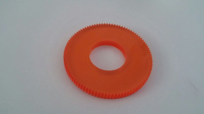
Next, the gear for the azimuth axis (base rotation), was designed in similarly, but the gerar ratio was kept to 1:5, i.e 100 teeth.
Electronics Production
I was involved in the producing a PCB which would house the motor drivers, LCD Display and the trigger switches for homing. This board would communicate with the Main board being produced by Suhail, from which it would recieve instructions on the text to display, and the number of steps to turn and the direction.The information regarding whether the north has been aligned (homing switch triggered), would be passsed on from my board onto the main board, where the calculation part happens.
I used the board that I had made in networking week , keeping this in mind
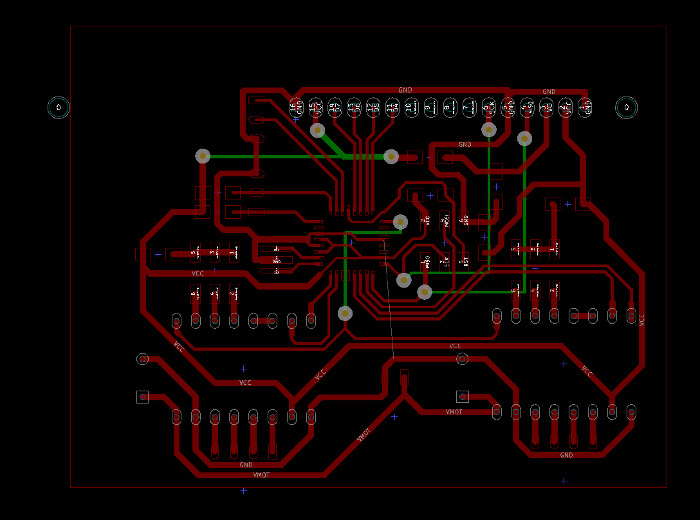
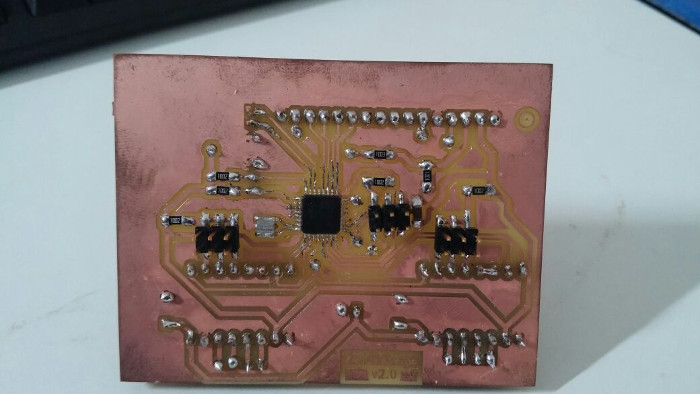
For more information on how I made, and the lessons learnt while making the board ,please refer to my Networking Week.
Programming
The software of the telescope has mainly two parts.First is the calculation and logic behind finding the object and tracking it, and Secondly the communication part between the app and the two boards.
For the programming part , I would be involved in doing the calaculation and logic part of the software.Because,astronomy was quite a new topic for me ,it took some days in understanding the logic behind tracking an object and get a sense of the differential equations used.
The "Finding", part was done before by myself during the machine design week, which was a set of formulas,changed into code.The major difference in the GO-TO system, from our group project phase, is the implementation of a repository of celestial objects in the the app.Previously, all the coordinates of our location, the celestial body's location , the date and time, was hardcoded into the program.However, in this project, these data would b fetced real time, from the app.
The basic fundamentals of astronomy used for this project is explained in the machine week.
The input recieved by the program would be:
- Right Ascension(Celestial Body)[RA]
- Declination(Celestial Body)[DEC]
- Current Date
- Current Time
- Current GPS location[LAT,LON]
THe small catch over here is that , the program assumes the mobile on which the app is running to be near the telescope, which it would be if not the bluetooth wouldnt work.
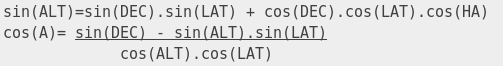
Given the inputs required, there are certain steps to get the Hour Angle, which would later be used to find the altitude and azimuth angles.
The final formula to be used is :
//to find Hour Angle (HA)
  //HA = LST - RA
  float get_ha() {
    float lst_ = get_lst_value(ip_long, ip_t, ip_date);
    float ra_ = ra_to_degree(ip_ra);
    float ha = lst_ - ra_;
    //float ha = (lst_ - ra_ + 360)- ((int)((lst_ - ra_ + 360)/360))*360;
    return ha;
    }

//to calculate Altitude(ALT)
 float get_altitude() {
   float alt = asin(sin(dec_to_degree(ip_dec)*pi/180)*sin(ip_lat*pi/180)+cos(dec_to_degree(ip_dec)*pi/180)*cos(ip_lat*pi/180)*cos(get_ha()*pi/180));
   return alt*180/pi;
  }

//to calculate Azimuth(AZ)
float get_azimuth() {
  float a,az,ha;
  a = acos((sin(dec_to_degree(ip_dec)*pi/180)-sin(get_altitude()*pi/180)*sin(ip_lat*pi/180))/(cos(get_altitude()*pi/180)*cos(ip_lat*pi/180)));
  a = a*180/pi;
  ha = get_ha();
  if (sin(ha*pi/180) > 0) {
      az = 360-a;
    }
    else {
       az = a;
      }

  return az;
  }
This would give the location of the celestial body,however, now to track the object throught the night is the challenge.
We would be using a Dobsonian mount for our telescope, which would mean our OTA ,isnt aligned to our equator.Hence for tracking an object both the motors would have to work, unlike equatorial mounts, which would only require movement along one axis.
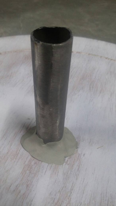
The velocities of the altitude and azimuth coordinates while tracking the object would be:
Where:
- Z: Zenith Distance
- A: Azimuth Angle
- phi: Latitude[LAT]
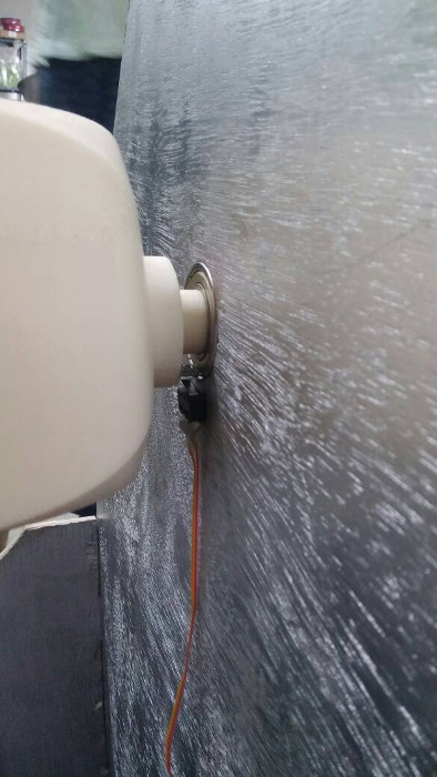
The corresponding accelaration of the alt-az coordinates are:
From the above accelaration equation is evident that the sign changes at the transit ,and the accelaration would near infinity at the zenith point.
Hence, this reveals a major drawback in using a Dobsonian mount for tracking,i.e, When the object moves past the zenith, there is small inaccessible blind spot around the zenith point, as the azimuth angle changes the sign.Here the accelartion would tend to infinity.
The angles from around 89.5 degrees to 90.5 is generally considered to be the blind spot.
To reduce the complication,in doing double differentiation, I decided to use a less effecient way of calculating the real time values by running the G0-TO function in a loop with a delay of 2 minutes.This however, would result in not a smooth tracking, but rather a choppier one, but in a scale of 12 hours tracking , the frame captured reduction would not be noticed .
In my method, once the track option is enabled in the request forwareded from the app, the program enters into a loop, wherein it would recalculate the position of the object every 2 minutes, convert it into steps.Then, find the difference of the current number of steps with the previous amount and then move the difference.The newly calculated step count would then be stored as the default value.This process goes on in repetitive cycle, until the object is out of sight of horizon, or until stopped.
alt_val = alt_val - al_delta;
      azimuth_val = azimuth_val - az_delta;
The above line of code finds the difference between the current value of steps and the newly calculated ones
al_delta = al_delta + alt_val;
       az_delta = az_delta + azimuth_val;
The above line of code stores the newly calculated value as the default value, this value would serve in the next iteration.
 if (ip_t[1]<59) {
        ip_t[1] = ip_t[1] + 1;
      } else {
        ip_t[1] = 0;
        if (ip_t[0]<23) {
          ip_t[0] = ip_t[0] + 1;
        } else {
            ip_t[0] = 0;
            if (ip_date[0]<30) {
                ip_date[0] = ip_date[0] + 1;
              }else {
                 ip_date[0] = 1;
                 ip_date[1] = ip_date[1] +1;
               }
The above line of code , takes into account the change in time when clock passes through one hour or one day.For eg. when the time is 20:59, then next iteration has to be 21:00
For the time being , it has been limited to 30 days in a month, I would later refine the code so that it takes it the alternating 30 &31 days, and would account for leap years and such.
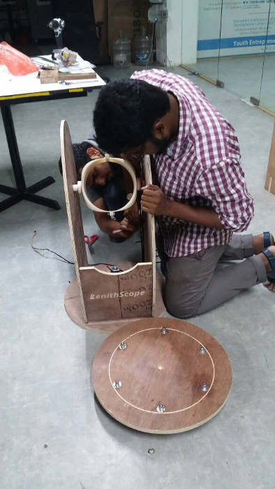
Assembling
To get started , I began with the base of the telescope. A 25 mm rod was fixed onto the stationary base, using Araldite, a hardner
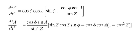
The homing switch , which is used to trigger, when the telescope is aligned to the zenith and the north had to be assembled.
For this, a mechanical switch with a wheel on the contact surface is used , so that it permits 360 degree rotation, without the limitation of a regular switch that would sacrifice some degrees of rotation, for its placement.
A smooth sliding contour has been laser cut , that would go over the wheel of the switch
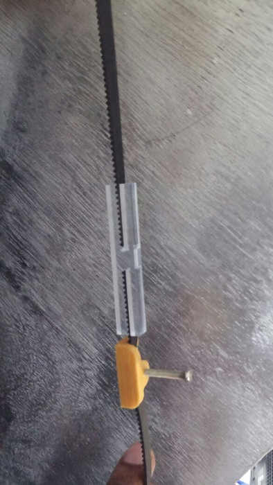
The next task is to tension the belt drives, for the lower base the design in itself would take care of the tensioning, however, the belt drive of the altitude angle, haas to be done manually, because it is an open loop belt
The belt used for driving the altitude axis is an open one, hence a joiner had to be made .The belt joiner is a laser cut negative profile of the GT2 belt.To adjust the tension further I downloaded a belt tensioner model from here.The belt can be tightened by screwing in on the belt.
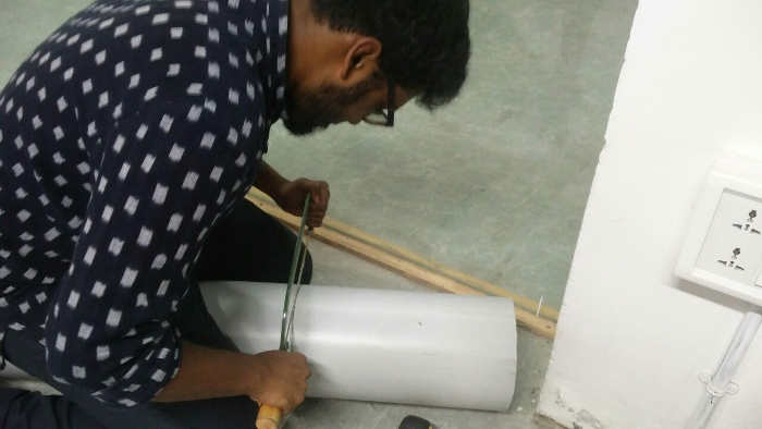
To make the Optical Tube Assembly (OTA),THE 1 meter long PVC tube had to be cut into two sections of approx 60cm and another of 15 cm, based on the 120cm focal length of the mirrors used.
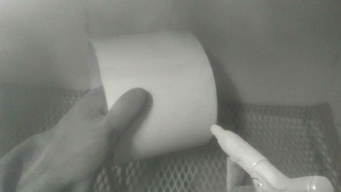
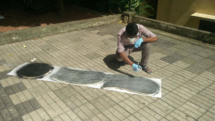
To give an aesthetic look to the project ,the wooden parts as well as the PVC tube has been painted.However, as the PVC tube was very smooth, I was apprenhensive about the paint sticking onto the surface.So, to have a bit of rough finishing on th etube, I sand blasted it.
The internal surface of the OTA shouldnt refelect light, and therefore painting it black,was essential
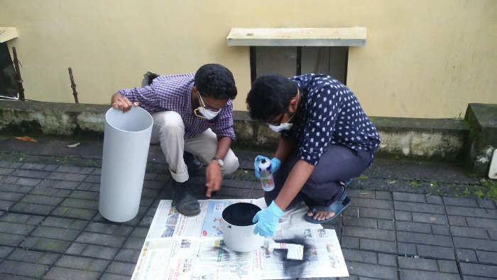
The wooden arms and base were painted for an aesthetic appeal.
The challenge in using a refelective telescope , is the alignment of the primary and seconadary mirrors.Moreover, as this project has two units of tubes attached by aluminum rods, it would be an extra effort in aligning the guide brackets such that the two pieces along with the mirror fall in the same line.
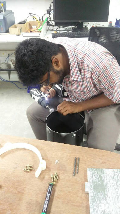
The mount for the primary mirror was quite fit inside the tube,bolts would be fixed around the mount, to give an additional support incase it came out of place if at all the assembly is affected by mechanical jerking.
The rods were kept in place by assembling the clips 3D printed before.
Errors Made
Well, over the course of this project development, there are a plethora of errors that I have committed, some are rather silly, while other may be due to lack of planning.Some of them are:
- Azimuth axis Belt tension : As I had mentioned above, where I used the common tangent formula for finding the distance between the centre of the motor spindle and the central rod.Well, that didnt actually work out exactly, but it was a very close approximate , this may have been caused by:
- The formula accounts for a straight line perfectly in line, which I thought would be applicable for a tensioned belt,there could have abeen a small sag, which changed the dimensions
- Another reason, I suspect is that,the approximations I had done in calculations would have caught up.
- Guide Rings Alignment : The guide rings that align the aluminium rods was not aligned properly in the first try.This was caused mainly, because I had aligned the guide rings to be parallel the the tube.However, the tuve wasnt cut exactly inline.THis caused the aluminium rods to be at different heights slightly, and therby the primary and secondary mirror to be misaligned.
- Outer Pass issue: This was a really silly mistake , that I had done. I had given an outer pass cut for the motor hole and the hole for passing the bearing.
- Rough Castor Wheels:The castor wheels that we had used was of poor quality, hence rotating the base was quite an effort for the motor. I resolved this by using bigger castor with big ping pong balls kind of wheels, also I am planning on making the gear bigger so that there is lesser load on the motor .
The issue was resol;ved by making the gear with a smaller diameter.I changed the number of teeth to 95, which brought the gear ratio to be 4.75.
This issue was corrected by aligning the guide rings properly,and reassembling the rods.
I then had to recut the base with inside pass, to get a tight fit of the motors and bearing.
Bill Of Materials
| Item | Price |
| 6" Optical Kit | Rs 8292 |
| Rack and Pinion Focuser | Rs 749 | GT2 Pulley | Rs 1000 |
| GT2 Belt | Rs 440 |
| Ball Bearing | Rs 240 |
| Ball Castors | Rs 210 |
| Small Castor Wheels | Rs 180 |
| Spray Paint | Rs 510 |
| 200 mm Dia PVC Pipe | Rs 480 |
| 3D Print- OTA Clamp | Rs 3150 | 3D Print- Guide Ring Bottom | Rs 1000 | 3D Print- Guide Ring Top x2 | Rs 1500 | 3D Print-Primary mirror mount base | Rs 973 | 3D Print- Primary Mirror adjustable base | Rs 442 | 3D Print- Laser Holder | Rs 520 | 3D Print- Secondary mirror- Spider net | Rs 445 | 3D Print- Secondary Mirror Cell | Rs 150 | ShopBot CNC Cutting | Rs 725 | Laser Cutting - Gears | Rs 100 | Laser Cutting -Box Enclosure | Rs 250 | Electronics Production- MotorControl/LCD Board | Rs 325 | Electronics Production-Master Board | Rs 200 | Total | Rs 21881 |
The overall cost of building the ZenithScope comes to 21881 rupees, which is approximately equal to 338 USD.
Future Scope
- The one feature we couldnt work on was to have the live stream networked over a server, so that multiple clients from across the globe can access it .Moreover, clients across the globe would also have control over the telescopes they choose over the app.So,building this feature would be a future scope.
- Using a thrust bearing instead of the regular ball bearing in the base would help in taking the axial load ,instead of transferring the whole weight onto the castors.
Download
- The 3D models can be downloaded from here.
- The DXF sketchs for the base can be downloaded from here.
- The SVG files for laser cut gears can be downloaded from here.
- The Arduino code that runs on both the boards can be found here.
- The files for my PCB can be found here.
Conclusion
The past couple of weeks has been hectic as well as intresting. The project was an exercise that went through almost all of the 19 weeks of Fab Academy, except for the molding and casting week.If time permits,a bit more finishing would render this project as a very good final product.
References
- The Principals of Astronomical Telescope Design - By Jingquan Cheng
- www.w8isms.blogspot.in
- HomeBuilt Reflector Telescopes- Sam Brown