Week #16 NETWORK AND COMMUNICATION
Assignment
As final project week is coming closer, I decided to work on a board that would be useful for my final project.As I would be working on buiding a circuit board that controls the LCD and motor drivers, which would communicate with the master board, I decided to take this week as an opportunity to explore how to network these two boards, and effectively relay communications between them.
Designing the Board
The board essentially needs a 12 pins for LCD, 4 pins for step and direction for the 2 motor drivers, and an ISP header, copuple of pins for reciever and transmitter so I chose an Atmega 328p as the IC for my board, as it has 32 pins for use.
The board was designed in KiCAD.
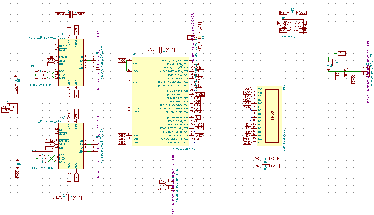
Once the schematic was done,a problem I faced was to find the footprint for the polulu motor drivers. Initially, I thought a 8X2 header pin would be fine.But then, going on to routing module, I found the mistake, and then had to download the library from here.
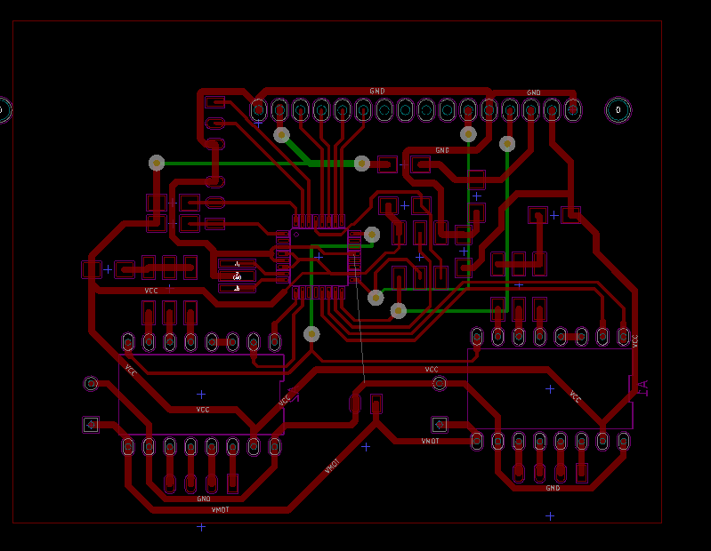
Once the footprints were assigned, routing all these many pins was a big headache.After trying for hours I still had around 8 jumper wires coming out , which would make the final product a real mess. Thankfully, my instructor came to the rescue, and brought that number by half, this reduced the overall mess, and made the board look a bit more aesthetically pleasing.What I learnt then, was that the "Flood Fill" option was a lifesaver, and could easily connect a net that has loose ends at many places. Also the intercative routing option in Kicad is really good , as it shows the routable options once you click a pad and move around the trace.
Millling the Board
Once routed I then added a name of the project at the bottom and started milling the board.
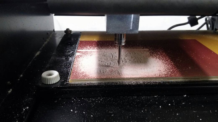
During milling, as the level of the PCB wasnt done right, it may have been caused due to the sacrificial layer not levelled properly, or there may be a fold or air bubble in the double sided tape that I stuck at the bottom of the board.This caused some areas of the PCB to be not milled properly, as the copper layer wasnt removed properly, but just rather scratched at the surface, I reran the mill at 0.12mm (default is 0.1mm) depth, which solved the issue.

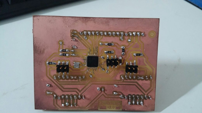
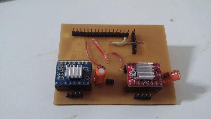
Stuffing the Board
The components used for this board are:
- Atmega 328p- x1
- 20Mhz Resonator- x1
- 10k ohm resistor - x5
- 1k ohm resitor - x1
- 100k ohm resistor - x1
- 22uF Capacitor - x2
- 10uF Capacitor - x1
- 1x8 female header pins - x4
- 2x3 Header Pin- x3
- 1x16 Header pin - x1
- 1x4 Header pins - x2
- 1x3 Header Pins - x2
Problems faced while making the Board
Even though,reading through the documentation, till now, may give a feeling that I had made the board in one go, the truth is that the final board is actually the second board i have milled and stuffed, this was mainly due lack of foresight.
In the initial iteration, I had kept the polulu motor drivers on the top, and hence soldering it from that postion was a very daunting task.Moreover, a 1x4 header pin(to the stepper motors) was coming right in front of it which made everything even worse.
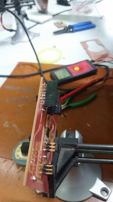
The board had to be redesigned(the one documented) , keeping the polulu motor driver footprint in the mirror image position of the previous one.
Programming the Board
For my final project, the board that I had made is supposed to relay messgaes ionto the LCD from the master board, and also send the number of steps to be moved along with direction to the motor drivers.For checking out , whether this works out fine, I decided to check whether, mesagges send by the master board is being displayed in the LCD connected to my board.
The master board used over here, is the board made by Suhail, for the final project
#includeSoftwareSerial softserial(3, 4); // RX, TX void setup() { softserial.begin(9600); softserial.println("Msg Transmitted!"); } void loop() { }
The above code is for the master board to begin communication, and to send a message to the slave board.
#includeLiquidCrystal lcd(12,13,A2,A3,A4,A5); void setup() { Serial.begin(9600); } void loop() { if (Serial.available()) { lcd.clear(); lcd.setCursor(0,0); lcd.print(Serial.readString()); delay(5000); } }
The above code, is for my board.It keeps listening for any communication through its recioever pin, and the string of data it recieves, would be displayed in the LCD .
I took some time to troubleshoot some issues, such as junk data coming in. This was solved by changing "serial.read" to "serial.readString".Also, as my soldering had not been done right,I also faced some issues due to loose contact, which I resolved then.
Download
- Trace and Cut PNG Files along with the code used can be downloaded from here.
Conclusion
This week was great in exploring how to communicate between two processors.Moreover, it helped me be one step closer to the final project.