- This week's lecture : Lecture
- Fab Tutorial Link : Tutorials
- Fab Tool's List : Tools List
What I did this week?
- Learned processes involved in using vinyl cutter machine.
- Learned processes involved in using laser cutter machine.
This week, Professor Niel introduced us Computer-controlled cutting. Laser Cutter and Vinyl Cutter are two machines used for this purpose. We were given 2 individual assignments and a group assignment for this week.
- Group assignment:
- Make lasercutter test part(s), varying cutting settings and slot dimensions
- Individual assignment:
- Cut something on the vinylcutter
- Design, make, and document a parametric press-fit construction kit, accounting for the lasercutter kerf, which can be assembled in multiple ways
1. Vinyl Cutter
The computer controls the movement of a sharp blade. This blade is used to cut out shapes and letters from sheets of thin self-adhesive plastic (vinyl). The vinyl can then be stuck onto almost any surface. Vinyl cutters are mainly used to make signs, banners and advertisements. Advertisements seen on automobiles and vans are often made with vinyl cut letters.
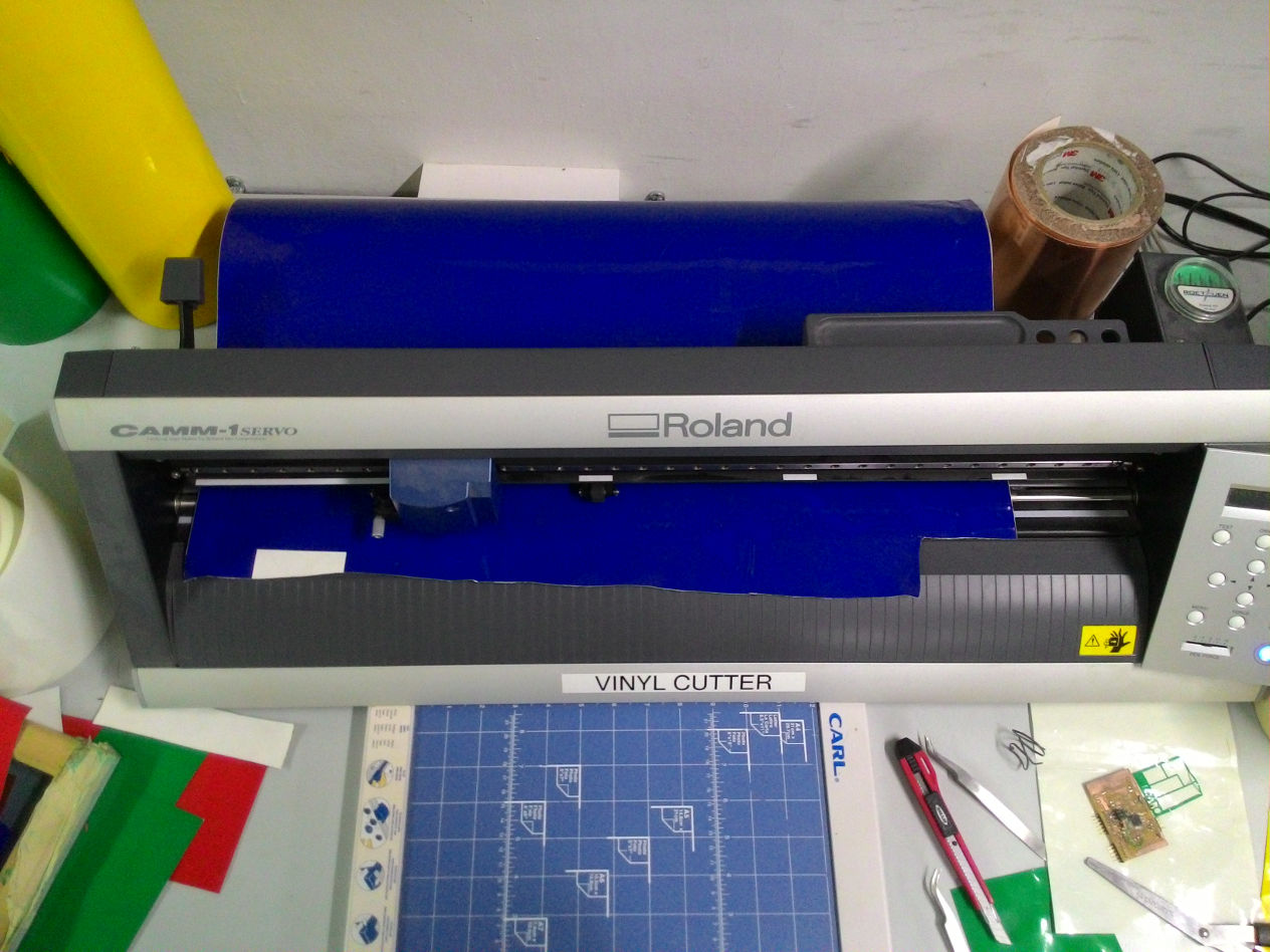
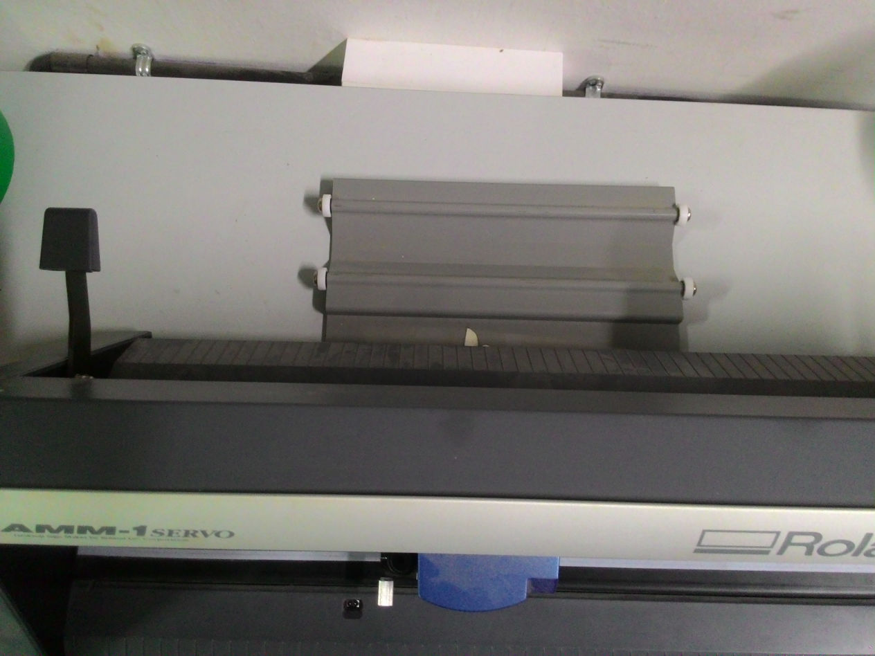
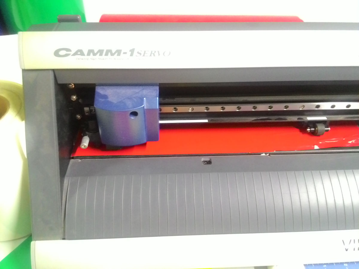
Our Fablab is equiped with a Roland CAMM-1 Servo vinyl cutter. Once understanding the basic usage, I decided to try a fab logo as a sample design.
i. Fab logo
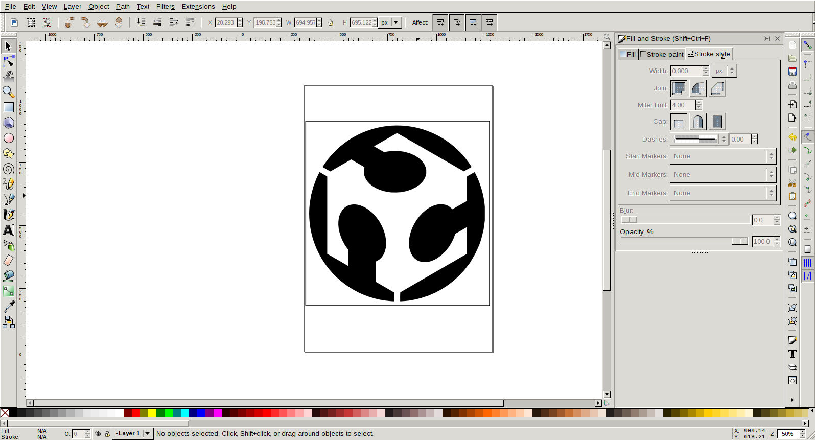
- I first downloaded FabAcademy logo from fab archive. And opened in inkscape.
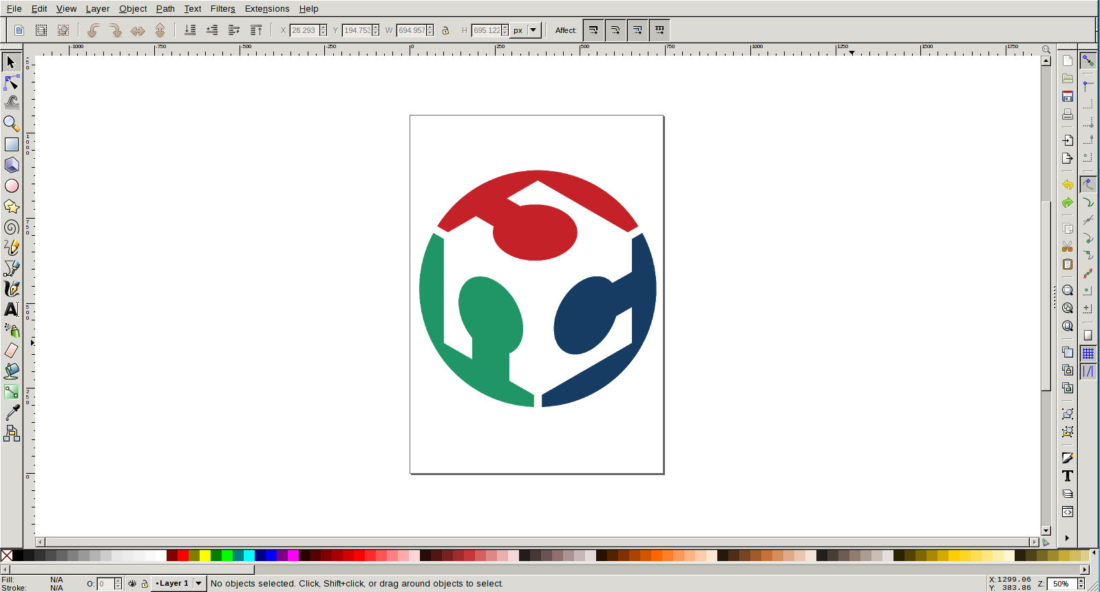
- I used keyboard shortcut Shift + Alt + B for tracing the bitmap image.
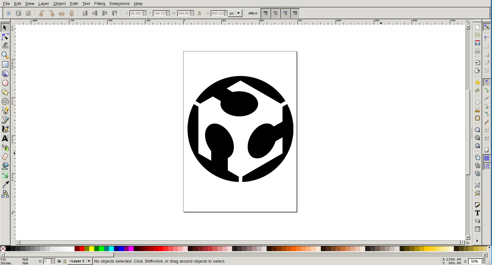
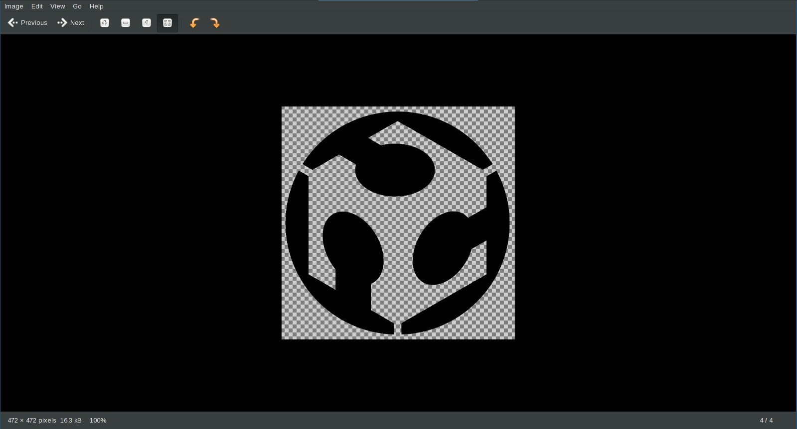
- Creating a border for easy removal of vinyl-cut image from sheet. Then image was exported to png.
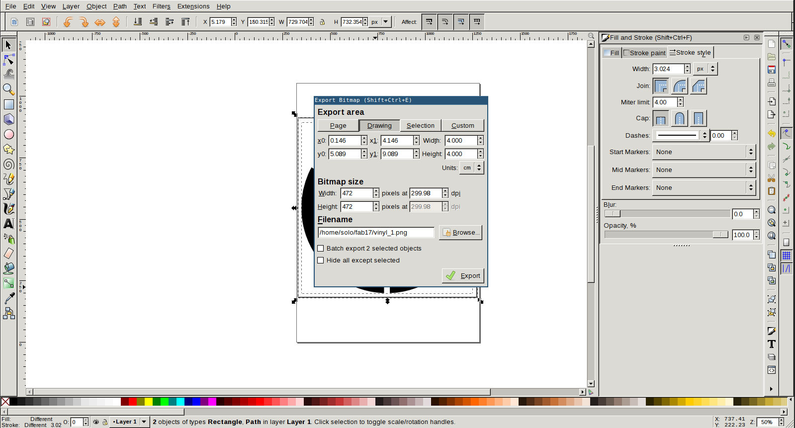
- Image size was too heavy. I need this sticked to use on my laptop. So I decided to scale it to 4cmX4cm size. I used GIMP for this.
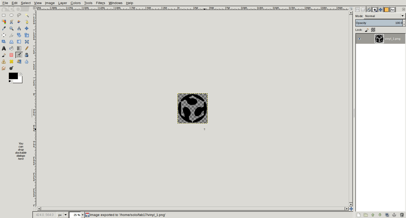
- This image was fed to vinyl cutter.
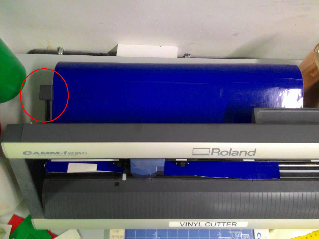
Initially I used blue colour sheet. Roll was placed on stand and end of the sheet was fed to the machine. Roll was locked by moving the knob to top.
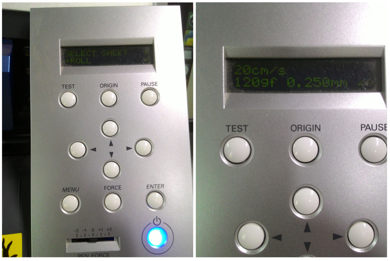
Sheet type is selected as roll and press 'Enter' button. To select a particular point as origine, long press on 'origin' button.
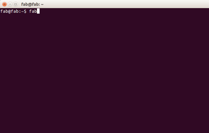
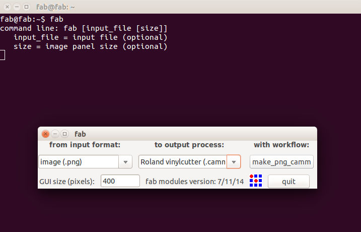
Now I have to pass image to the machine. For this a command line utility is used. Open a terminal and type 'fab'. This would open our software.
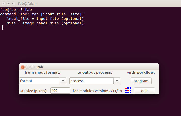
Choose input image format and output process options from select box and press 'make_png_camm' button.
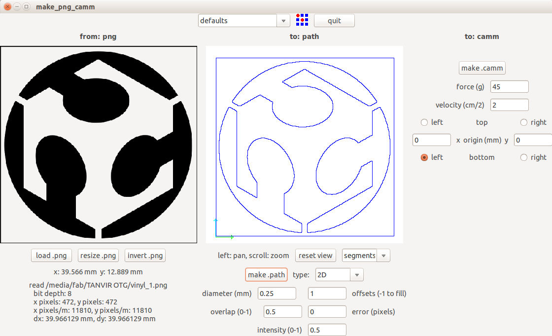
Load the image by clicking on 'load.png' button
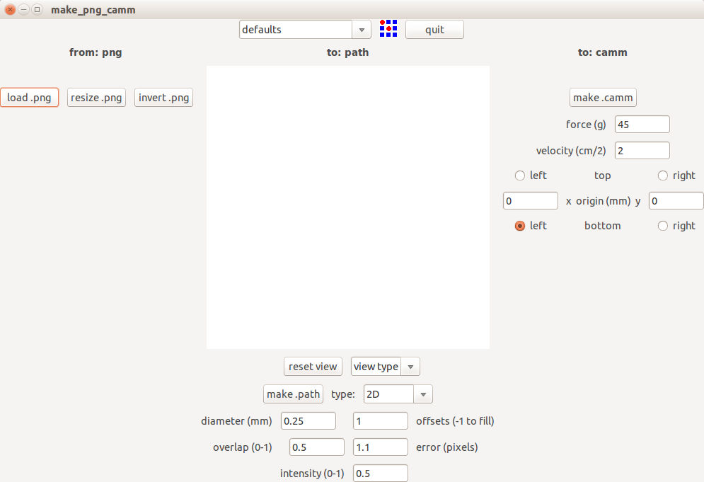
Load the image by clicking on 'load.png' button. Choose required settings and 'make.camm' button and then send the image.
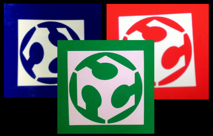
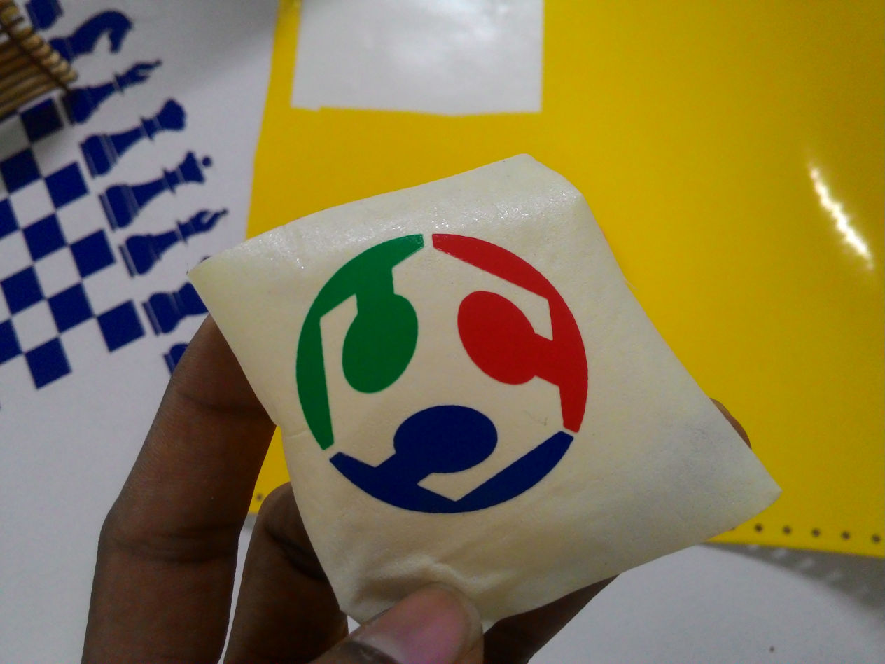
To get 3 different colors for logo, I printed same logo on sheets of 3 different colors and then interchanged the parts.
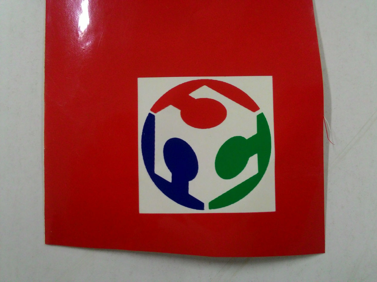
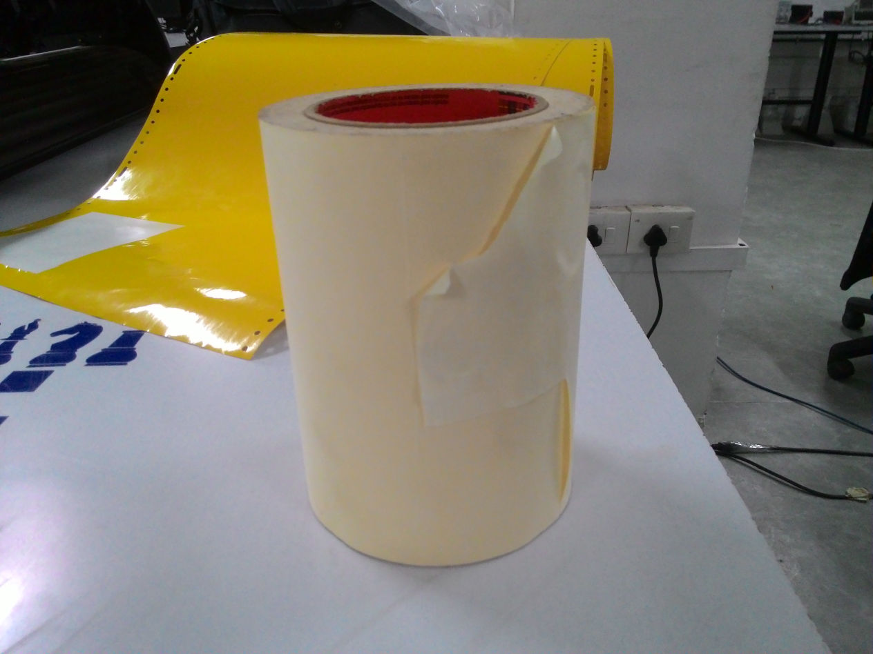
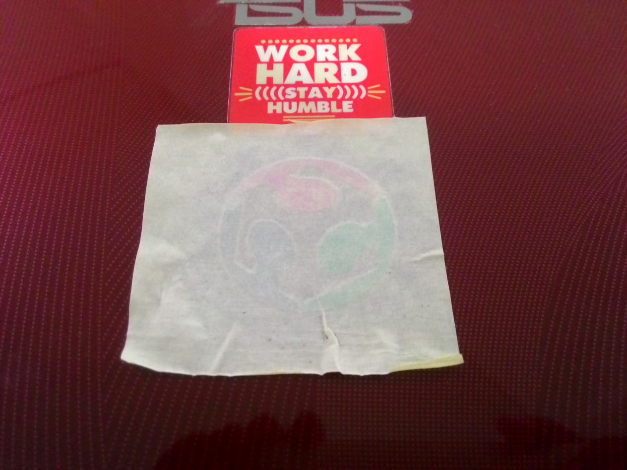
Now its time to transfer the sticker into the laptop lid. It was done using tap shown below. All I had to do was to put the tape on the sticker and pull the tape. Now the sticker is on the tape. Then just press it on any surface, in my case my laptop.
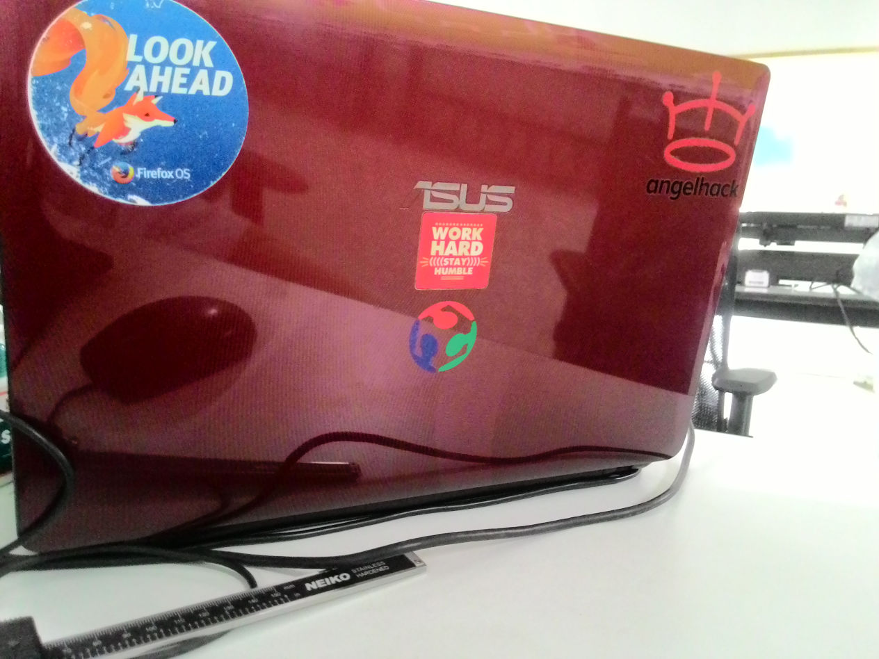
Done! A cool FabAcademy logo on my laptop lid :)
ii. Assignment
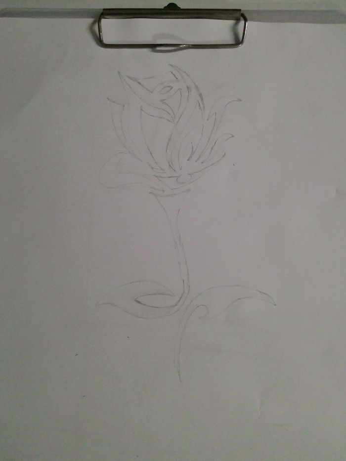
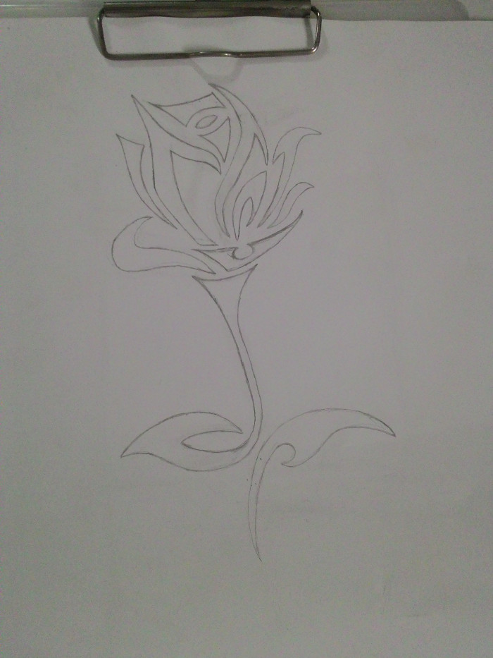
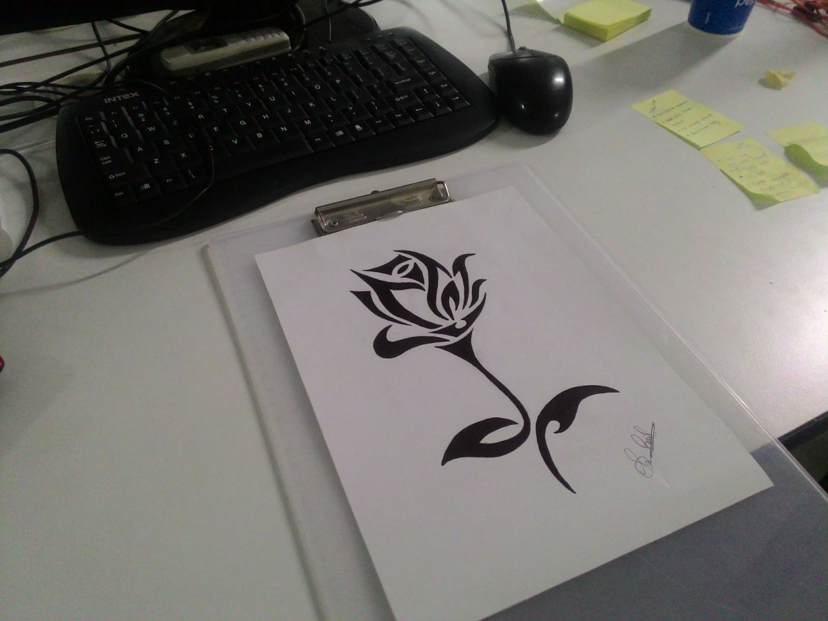
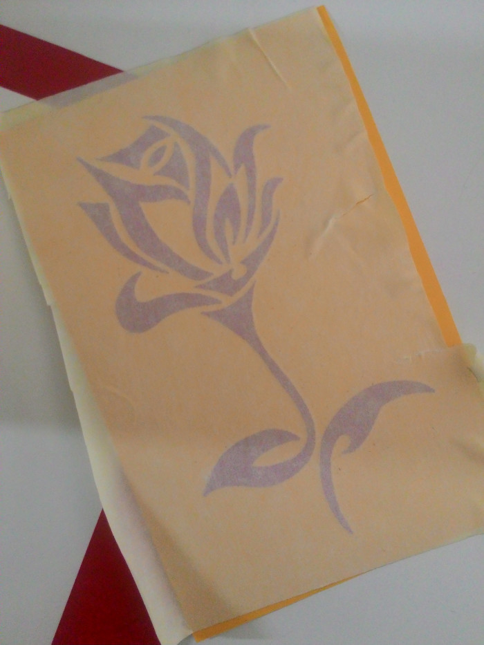
I like pencil drawing very much. For assignment, I planned to draw a design by hand and then scan it & create a vector image. I found an image of a flower online and I drew it. Here are some photos of drawings :).
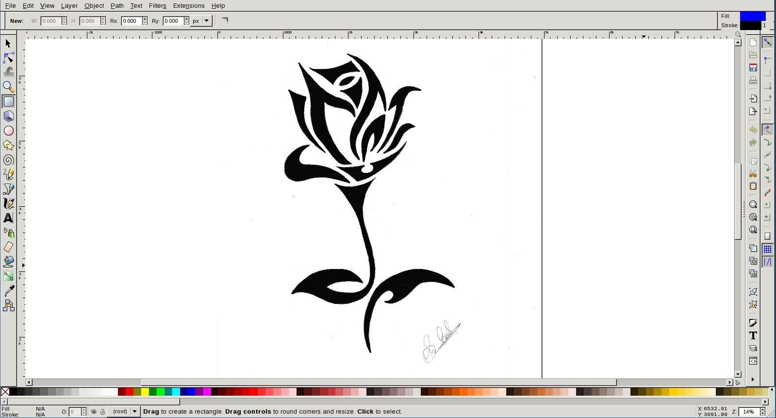
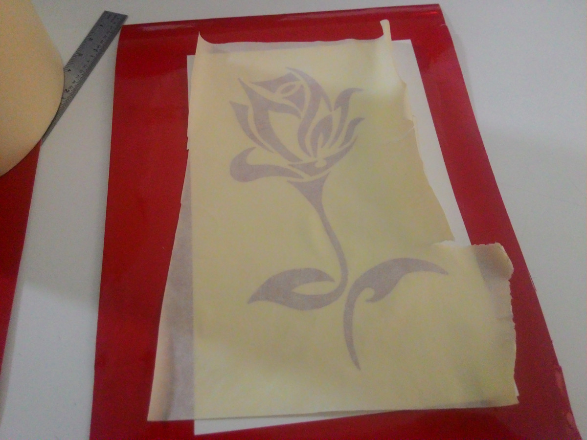
I scanned the image and imported it into inkscape. Then used Shift + Alt + B to trace bitmap. It was then exported to png.
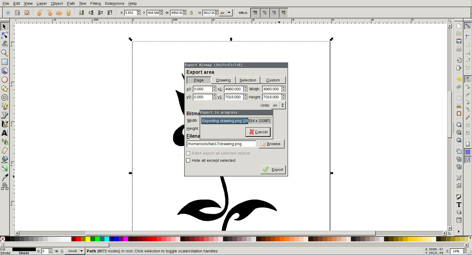
I added a border for image and then scaled image to 10x15cm size.
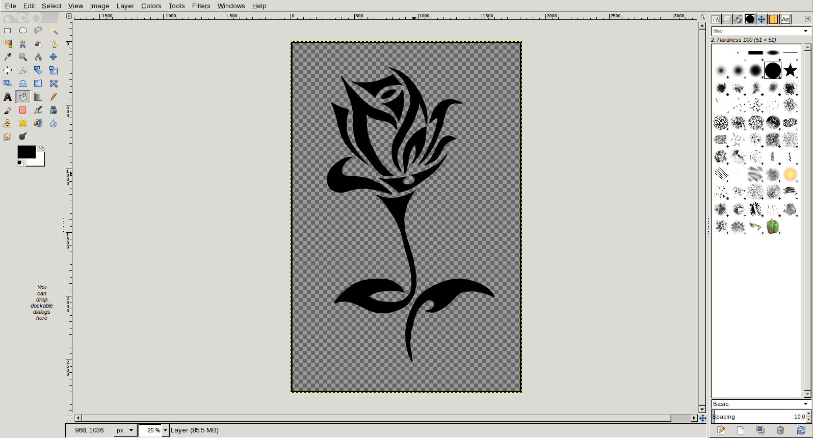
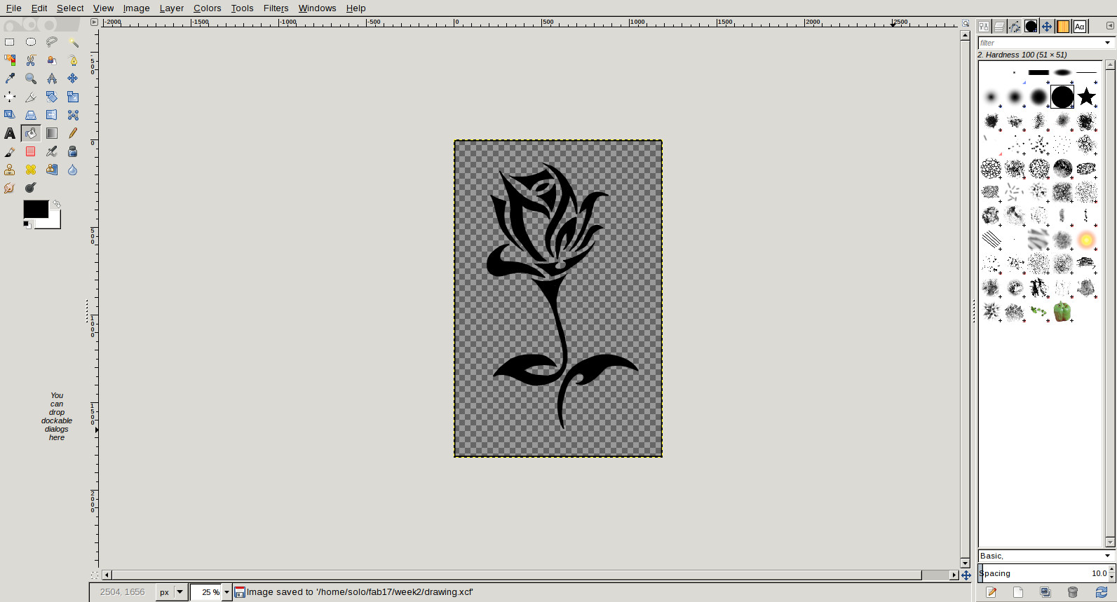
Image was then fed to vinyl cutter. I used red sheet first. Command line tool was called using command 'fab' and image type was selected as explained in previous experiment.
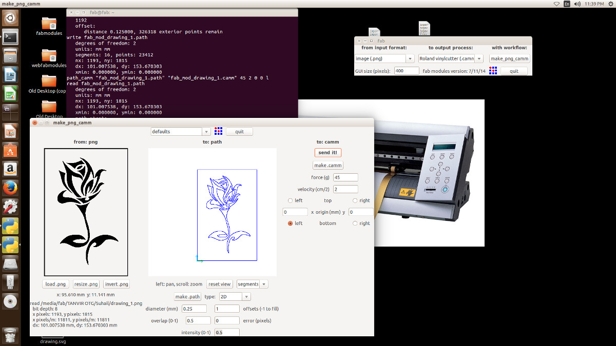
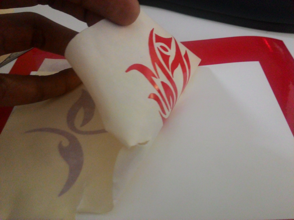
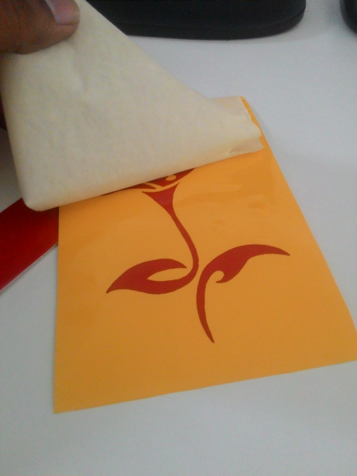
Frame was removed from printed sheet to get the actual image.
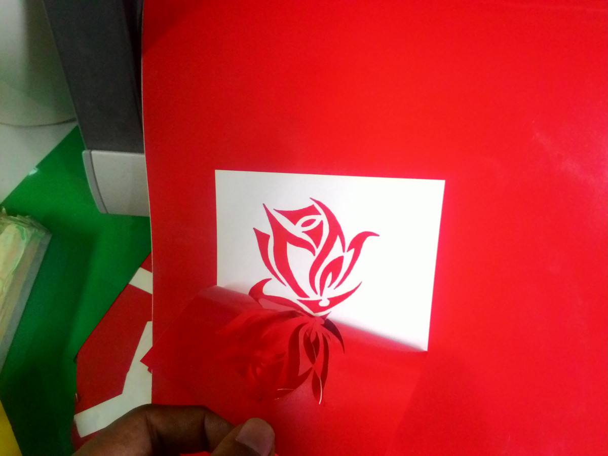
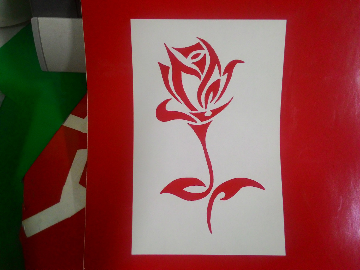
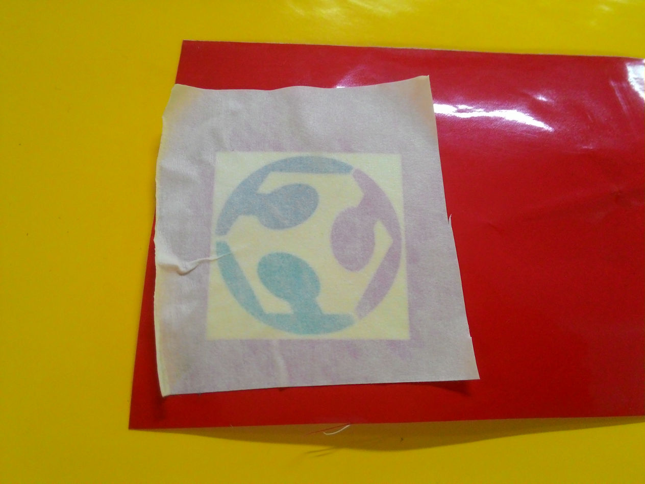
Image was then transferred to an yellow background.
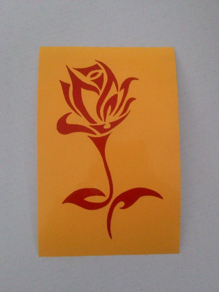
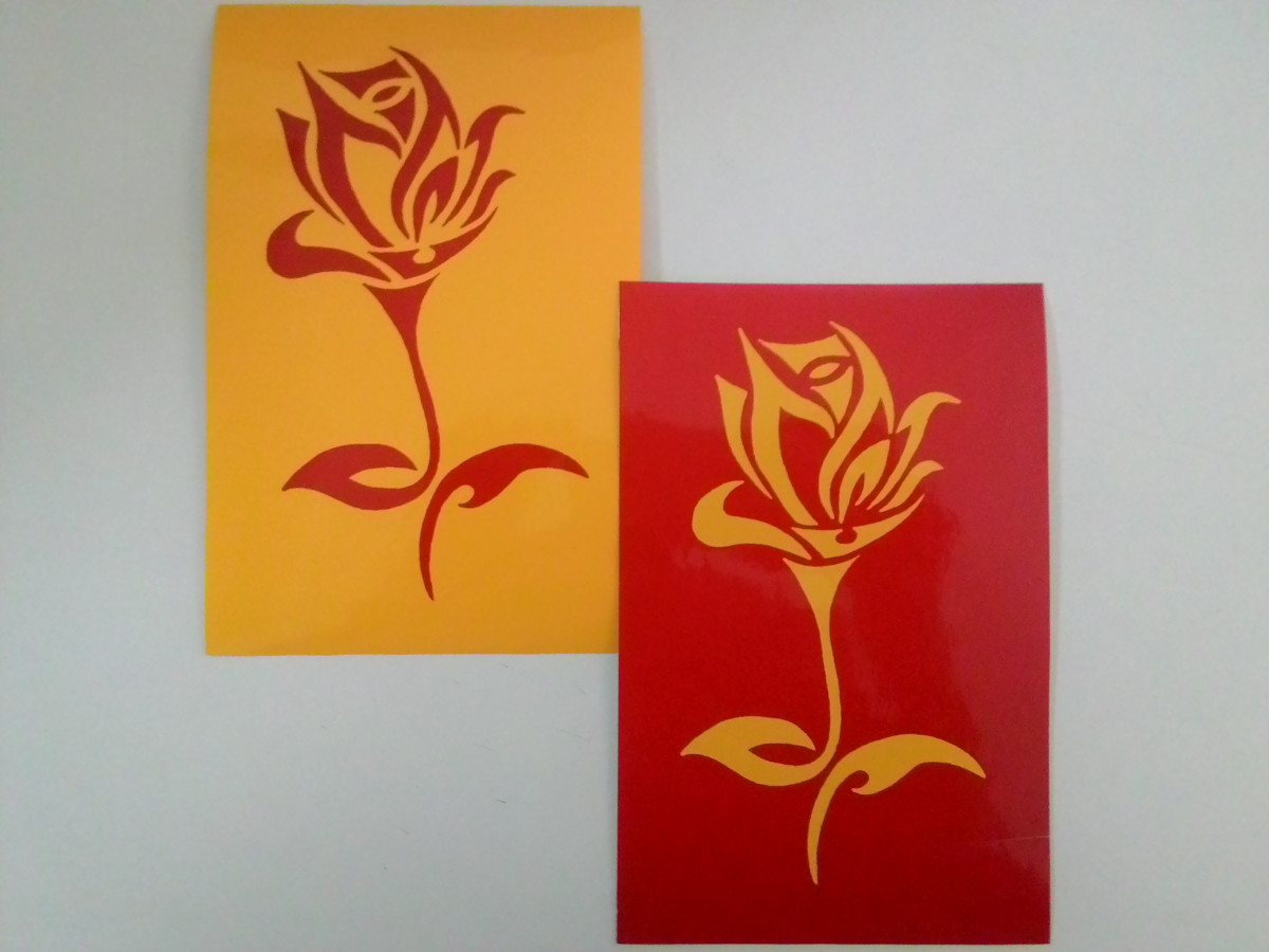
I had also printed an yellow image and used it on a red background. Here are the output. Hope you like it.
2. Laser Cutter
Laser cutting is a technology that uses a laser to cut materials, and is typically used for industrial manufacturing applications, but is also starting to be used by schools, small businesses, and hobbyists. Laser cutting works by directing the output of a high-power laser most commonly through optics. -- Wikipedia
We have a Trotec Speedy 100 CO2 laser cutter and engraver, at Fablab Kochi, which is capable of cutting and engraving on a wide range of materials. We have acrylic of various thickness, plywoods and cardboards for doing assignments.
Laser cutter machine is shown in the image below. On the left side is the exhaust chamber which is capable of absorbing fumes that arise during cutting/engraving.
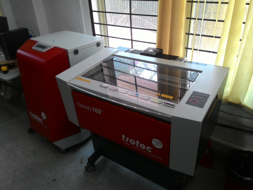
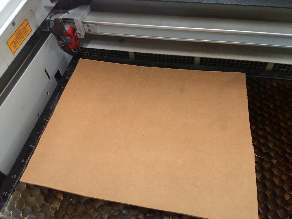
Material to be cut/engraved is placed inside by opening the glass lid. This laser cutter has a bed size of 600x300cm.
First thing to do is to focus the laser beam. For this, focus tool(shown below) is used. This tool is hanged on the laser head and the bed is moved up, using control keys, until the material just touch the focus tool. Focus tool will fall at this point.
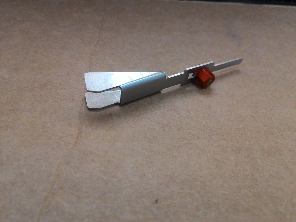
Video below shows a demo of focusing.
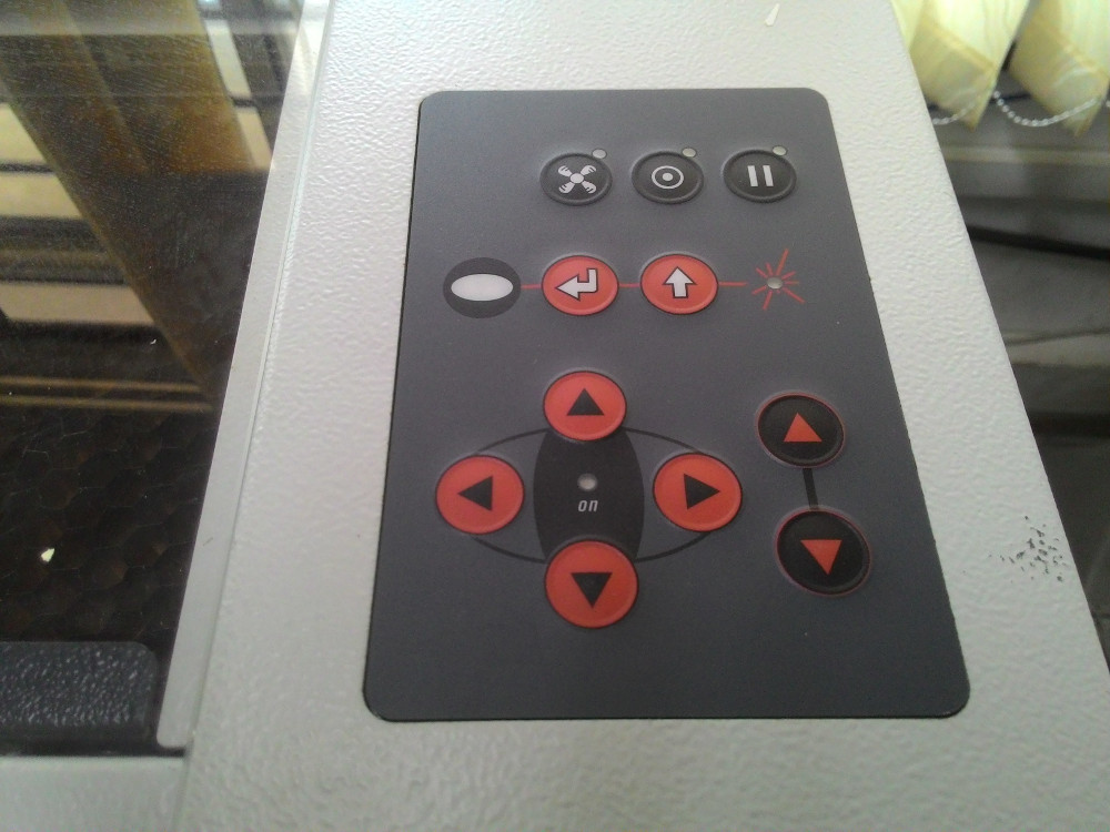
Image below shows the control keys available in trotek machine. Bottom right up/down buttons are used for moving the bed up/down. Bottom left buttons are used for moving the laser head in XY plane. Last button on the top row is pause button.
Notes:
- Laser is controlled by speed, power and frequency values set in Trotek's software. In our lab we have already saved these values for cutting and engraving, corresponding to each material available in lab. It will save lot of time in coming days.
- Make sure your material is suitable for using in the machine. Otherwise, fumes from the material might damage the lens.
- Never leave the machine unattended while its working.
i. Group Assignment
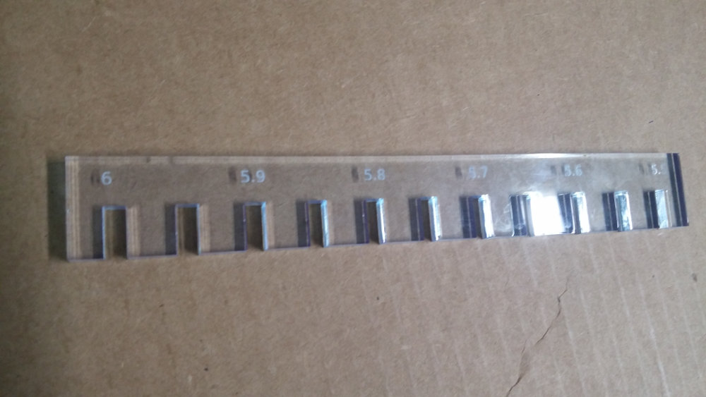
We have acrylic (of thickness 3mm, 5mm and 6mm), cardboard and plywood. We 5 students decided to take one each. I took acrylic of thickness 6mm. I used openscad for doing parametric design of comb with slits of various width.
Openscad was more easier for me compared to freecad. After designing comb with necessary parameters, code compilation is done using keyboard shortcut F5. Openscad Cheetsheet helped a lot.
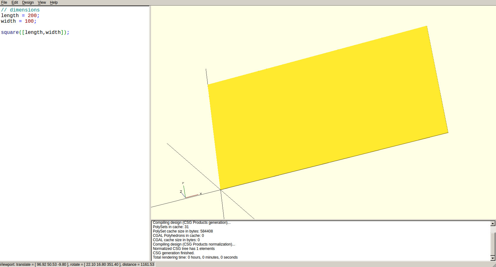
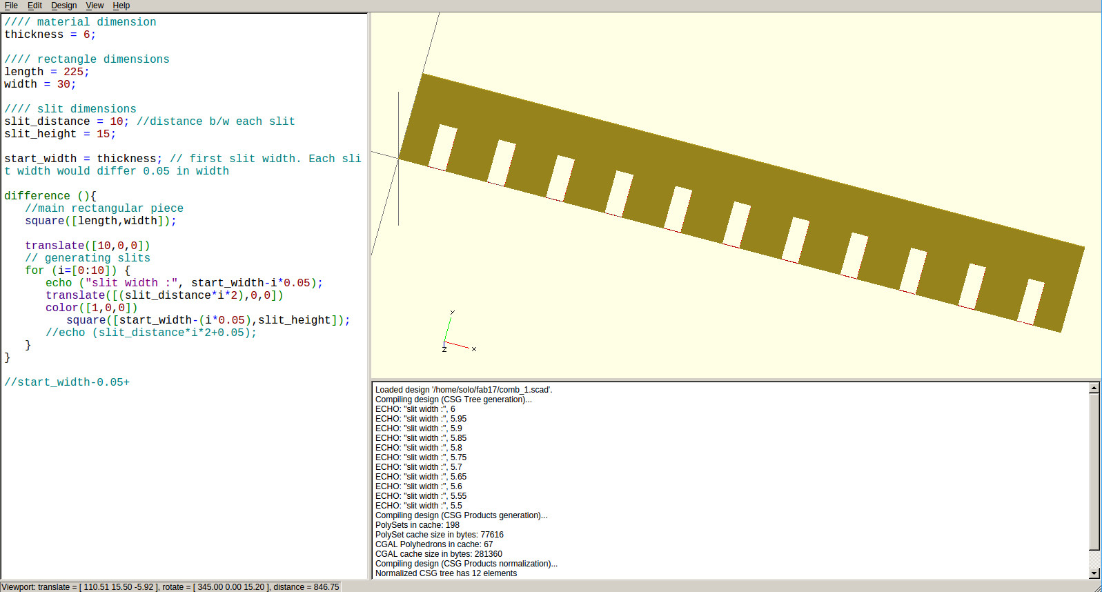
Design is rendered using keyboard shortcut F6.
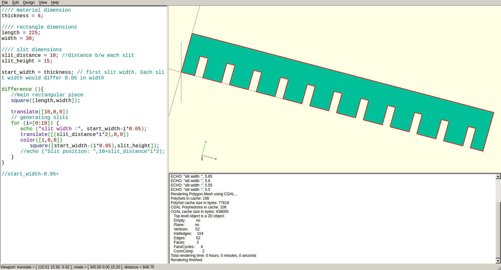
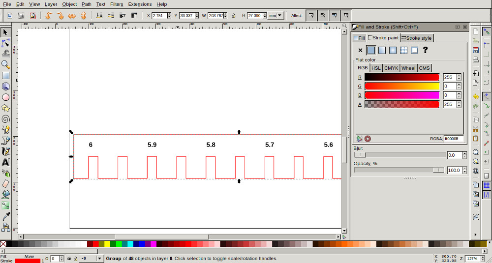
Design was then exported to dxf file (File > Export > Export as dxf) for processing in Laser Cut Machine. Below is code I used for this design.
//// material dimension
thickness = 6;

//// rectangle dimensions
length = 225;
width = 30;

//// slit dimensions
slit_distance = 10; //distance b/w each slit
slit_height = 15;

start_width = thickness+0.5; // first slit width. Each slit width would differ 0.05 in width

difference (){
    //main rectangular piece
    square([length,width]);

    translate([10,0,0])
// generating slits
for (i=[0:10]) {
    // echo ("slit width :", start_width-i*0.05);
    translate([(slit_distance*i*2),0,0])
    color([1,0,0])
    square([start_width-i*0.05,slit_height]);
    //echo ("Slit position: ",10+slit_distance*i*2);
}
}
Image was edited using inkscape. Measurements were added and then outline color changed to red.
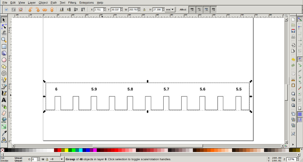
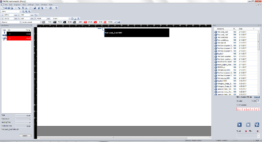
By pressing ctrl + P, image was set ready for laser cutter software after setting material type as acrylic. After setting the focus and origin in laser machine, design was fed to it.
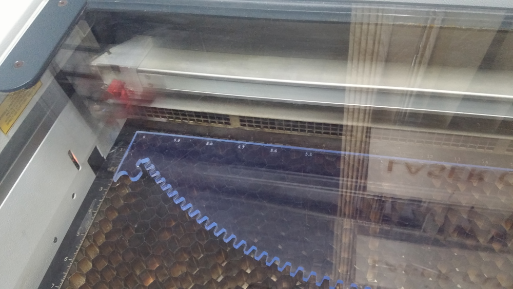
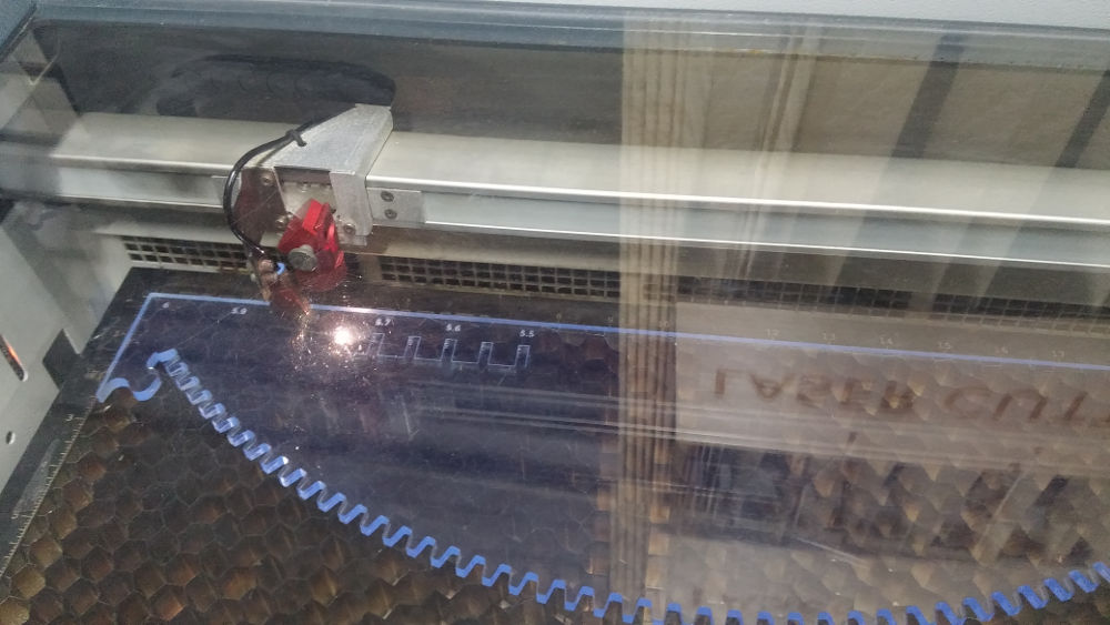
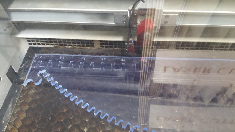
So, here is my final output.
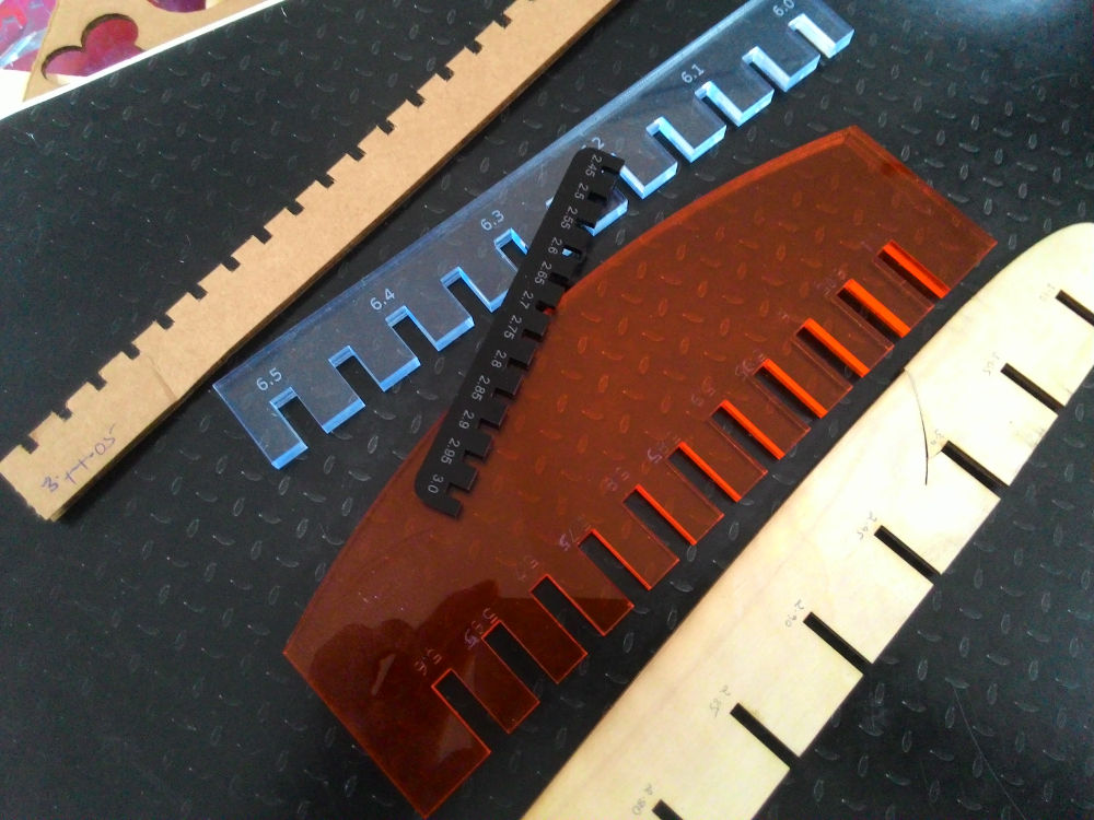
This is a group project :p Here is our all works together. Now we can easily check fit width of any material available(in our lab).
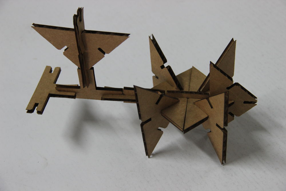
PressFit Construction Kit
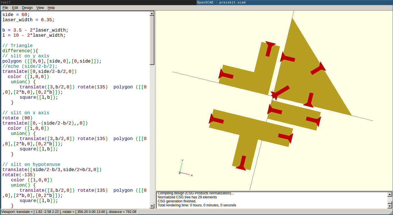
I was so confused about deciding what to build for this assignment. I started doing many sketches. Atlast I decided to try the following design. I am designing it in OpenScad as parametric design. Also, OpenScad cheetsheet helped a lot.
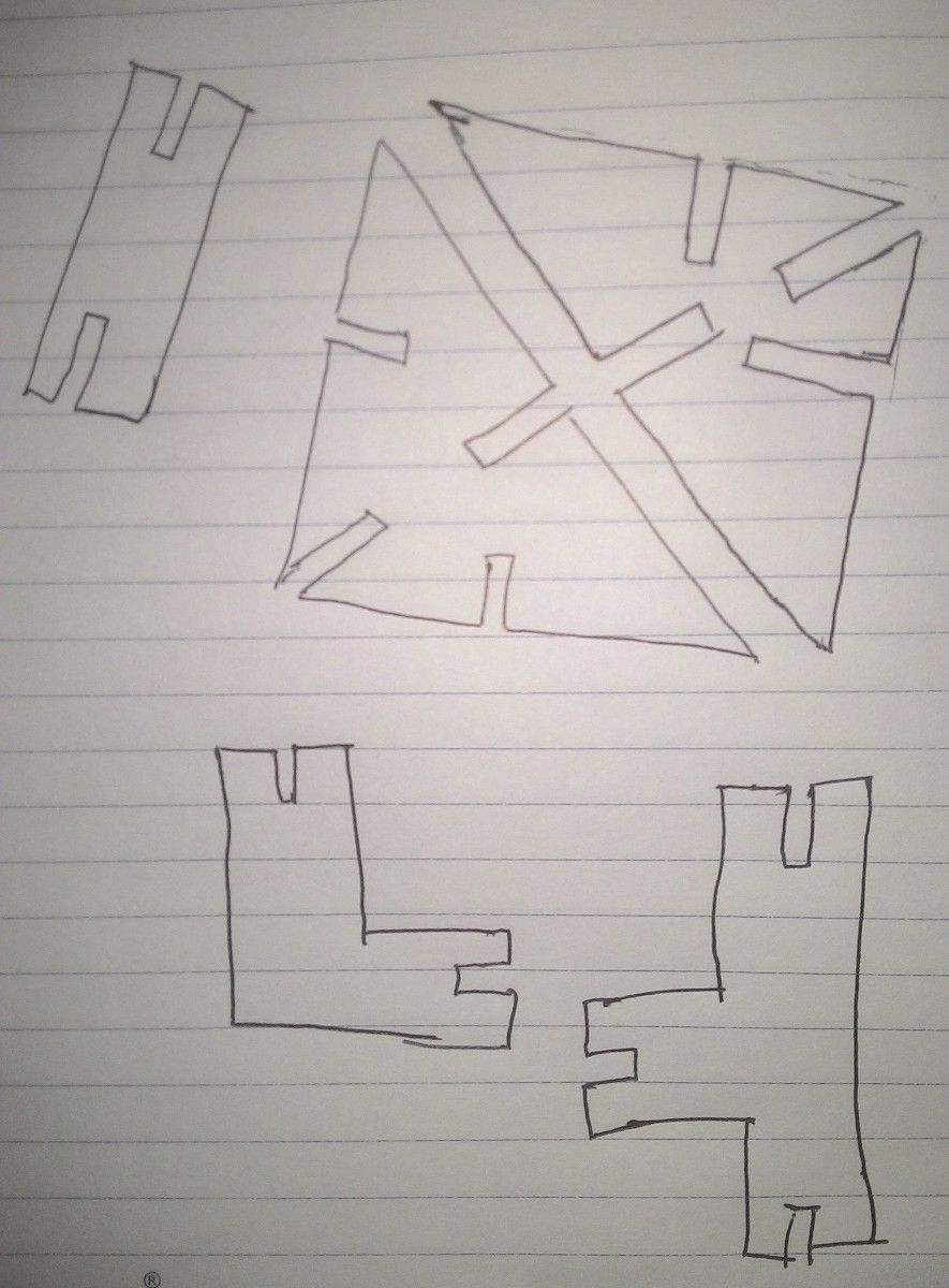
My instructor Sibu advised to add chamfer while designing. I didn't know what it was until then :). I started with a triangle design in openScad. polygon() function was used for this.
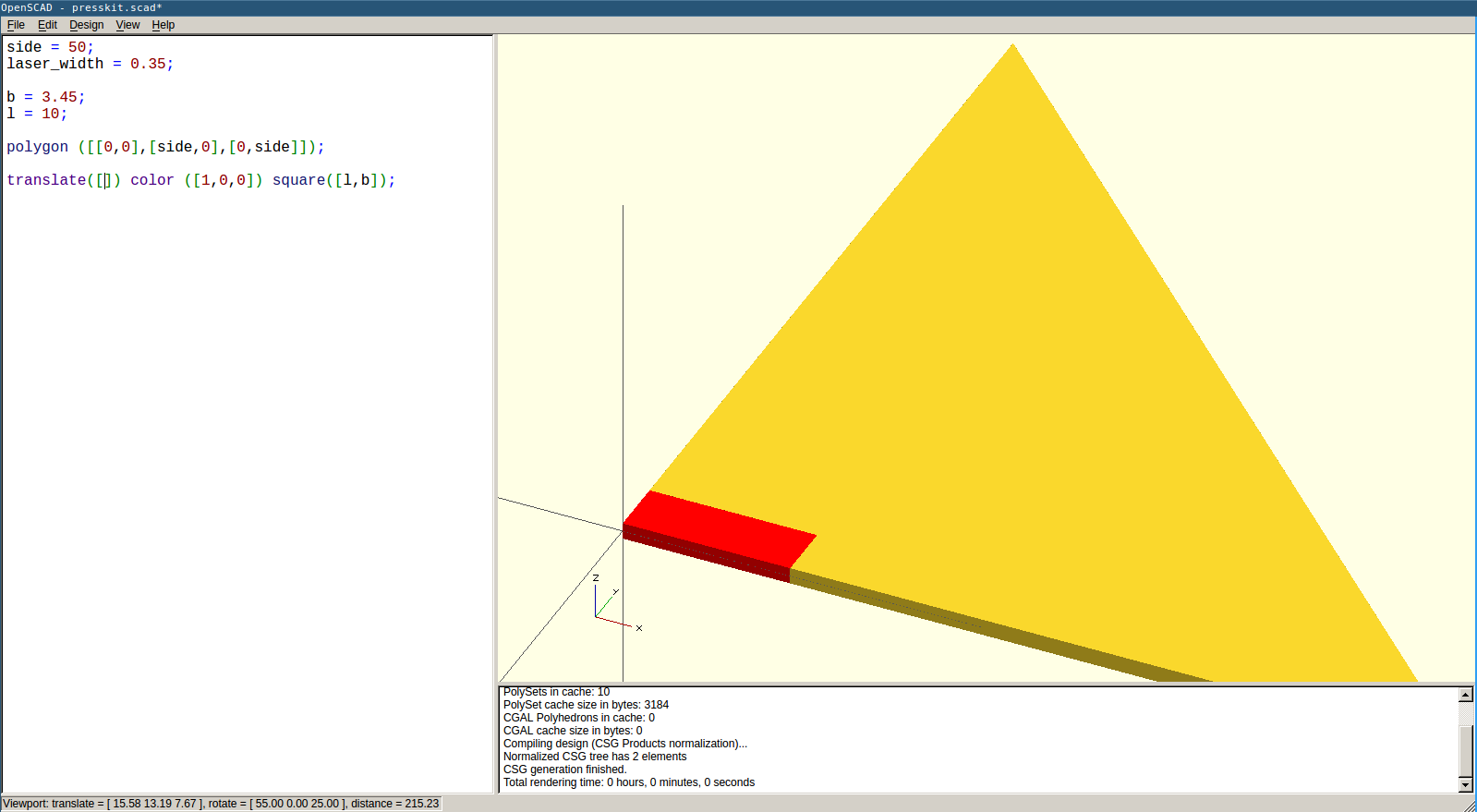
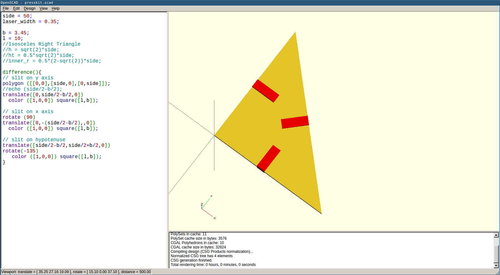
Using square() function I drew rectangular cuts. Their position were aligned using transform() and rotate() functions.
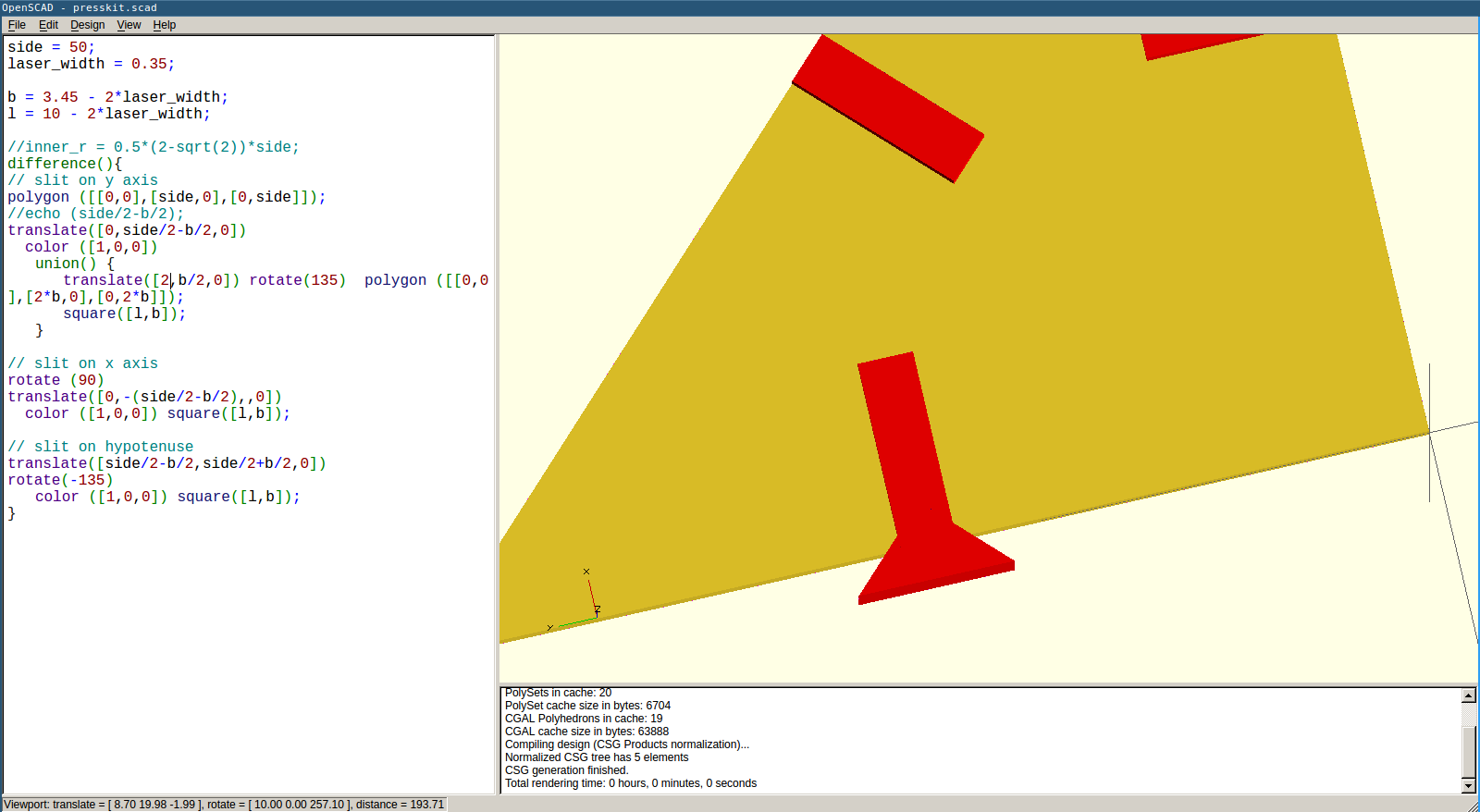
Adding chamfer
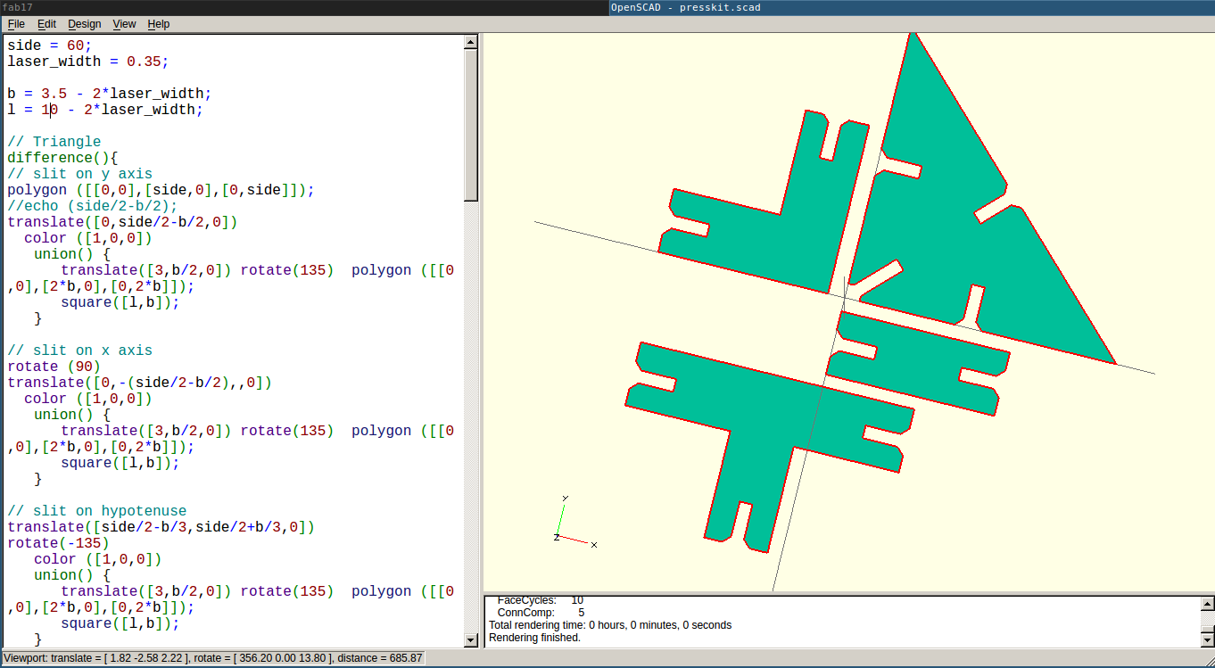
Then these codes were put inside difference() function for producing the required shape. Difference function removes the common parts of the designs.
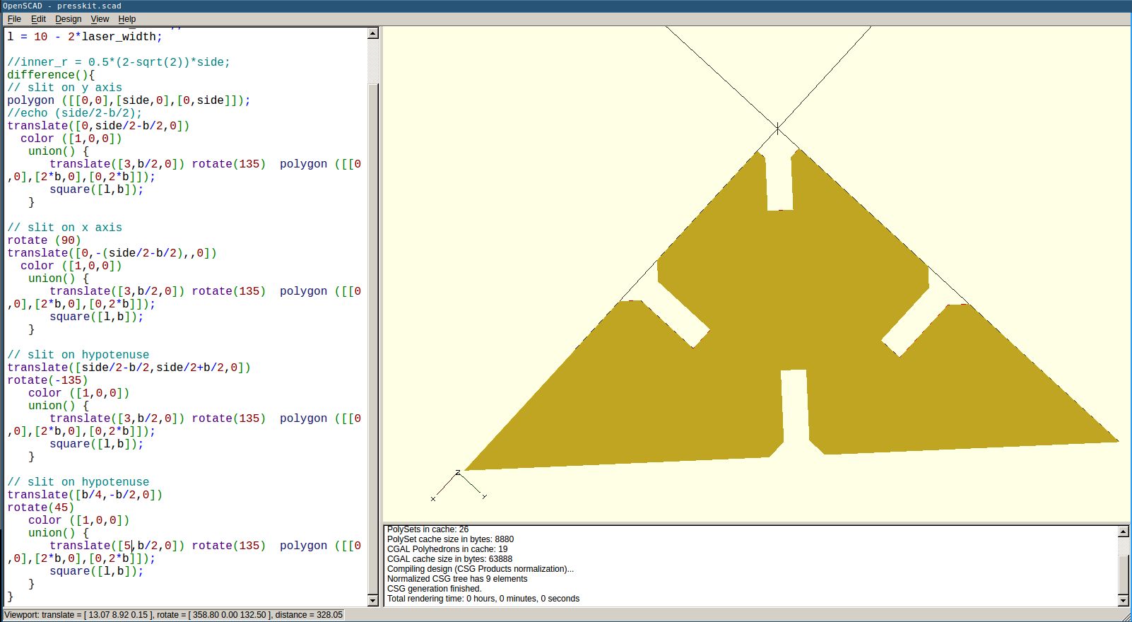
Here is the completed design screenshots.
I tried cutting some samples initially.
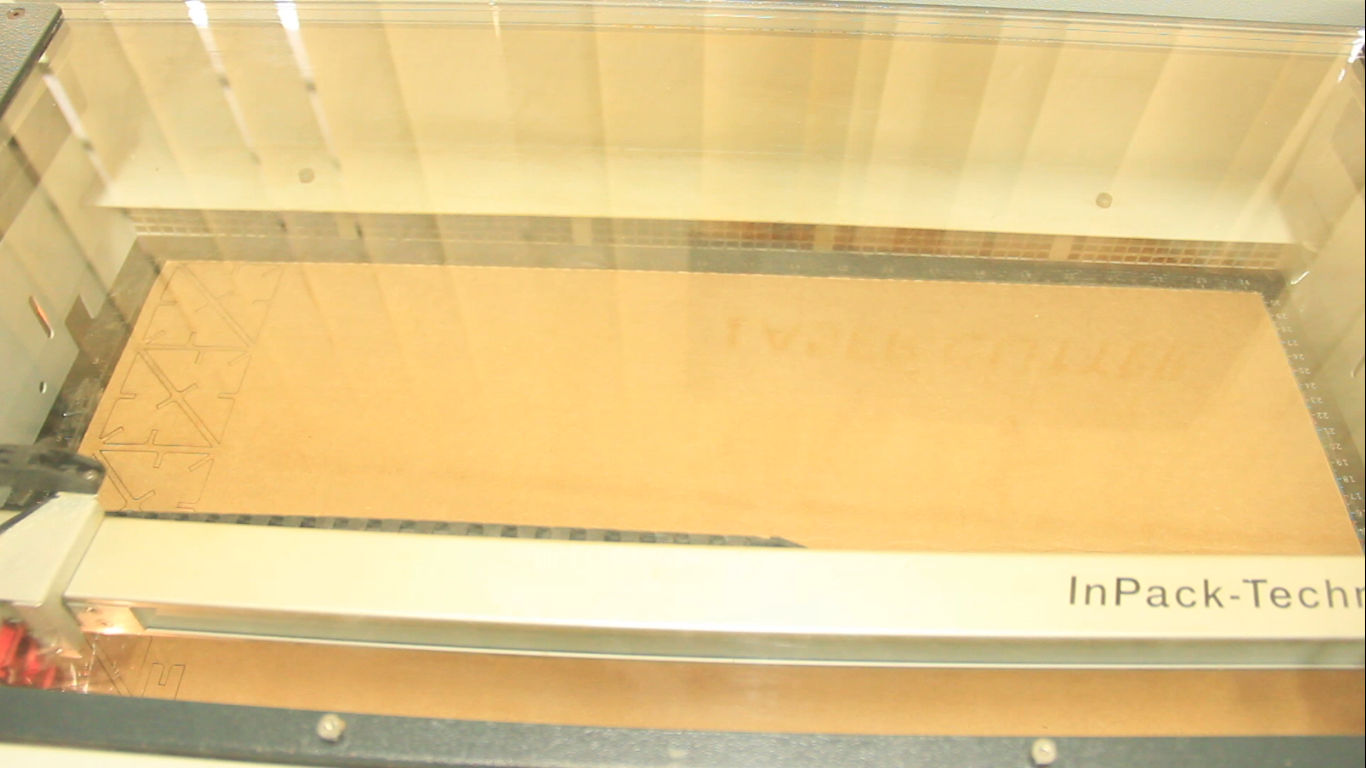
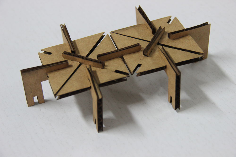
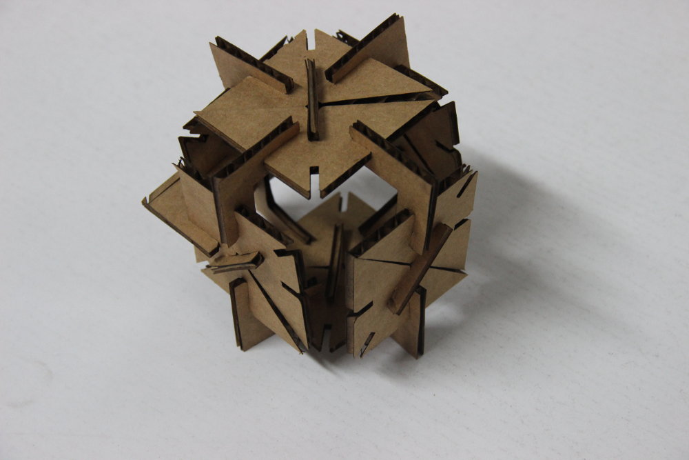
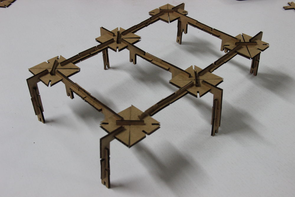
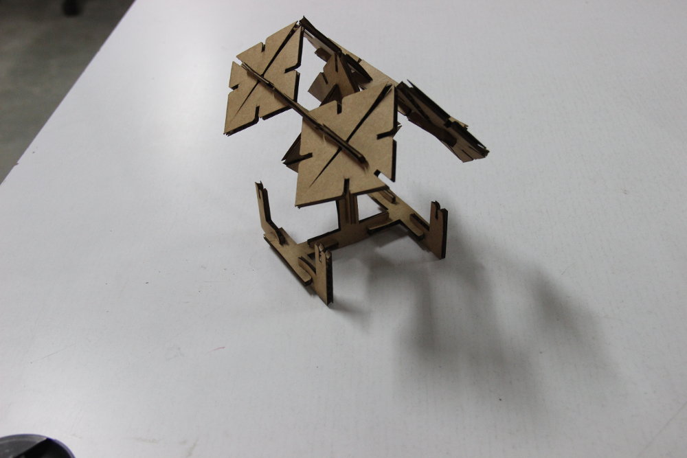
Samples worked fine. So, I arranged whole design in a full sheet and loaded into Trotek. All the pieces together looks like this.
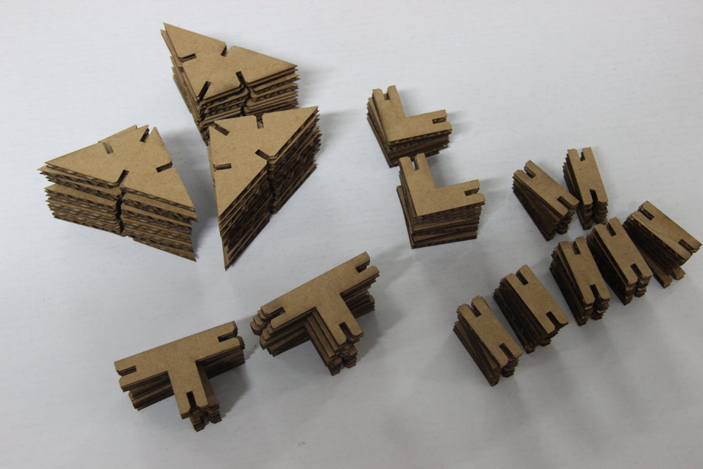
Pressfit kit are meant to design many shapes using these few types of pieces. Here are some shapes I tries using my Pressfit Construction kit. Download and try it yourself (if you like it :P).