We are undertaking the development of a “Relief Plotter” that pushes up pins arranged in a grid. The machine pushes up the data three-dimensionally, it looks like a relief by the height difference of pushed pins. As the first prototype, it consists of the following elements.

We think that this machine will lead to Kohie's final project.

And it can also be applied to the data visualization that Saki is working on as her private project.

This machine consists of 3 components.
So we made each prototype separately and check the mechanisms and design notes of them.
At firts, we made a stage that moves in X-Y direction with cardboard. This is based on Nadia’ MTM kit.
Nadia's design was too big for our lazer cutter, so we redesigned enclosure data with Fusion 360.


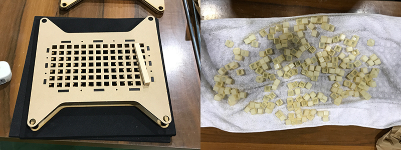
This components is attached to the stage and moves in X-Y direction. After moving to the specified position, it pushes up the pin above. We tried to realize it by using stepper motor and rack and pinion gear. The gears were made of MDF (5.5mm) and the enclosure made of cardboard (5.0mm).


base_complete(.ai): Download the file
base_bottom(.ai): Download the file
gantry_complete(.ai): Download the file

pinpusher_gear(.ai): Download the file
pinpusher_body(.ai): Download the file
pinpusher_spacer(.ai): Download the file
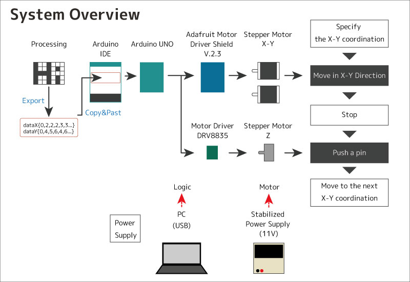
We used arduino Uno and Adfruit motor shield.And we used library,Adafruit_MotorShield.h.


We Add Z moter system to XY motor shield.And Add iniciallize buttons.when we integrated, we do not have enough power,sometimes it stopped.We fixed friction of X,Y,Z axises.Then it moved smoothly.

6 x SPEED
we need coordinates of image what we draw.So we made editor using processing.I learned processing from thie site.