Assignment 10
output device
Have you:
- add an output device to a microcontroller board you've designed and program it to do something
For this homework, I decided to make a board that can control 2 motors because I think use it in my previous final project (Make Sandwich Machine). I base my design on that of my friend Gonzalo, but design it myself.
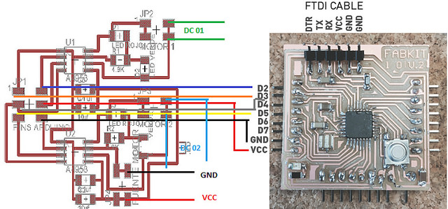
I use a a4953 H-bridge
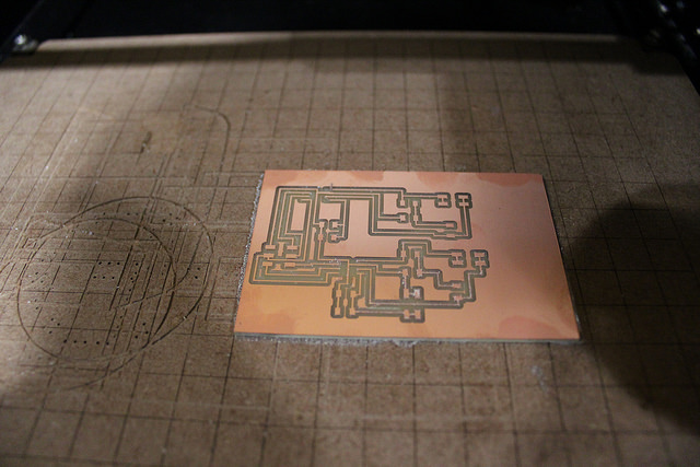
I added my name when I finished designing the board in Eagle
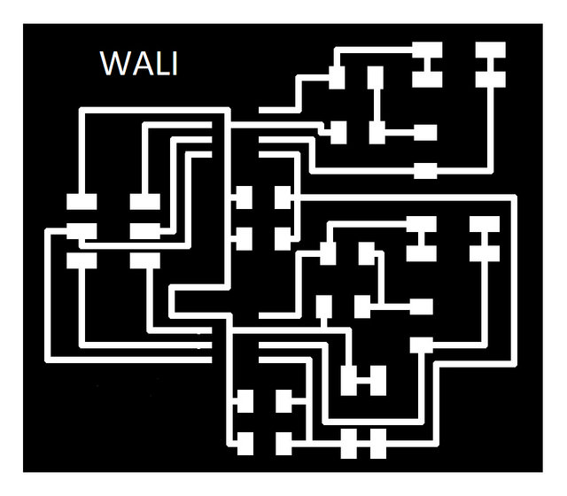

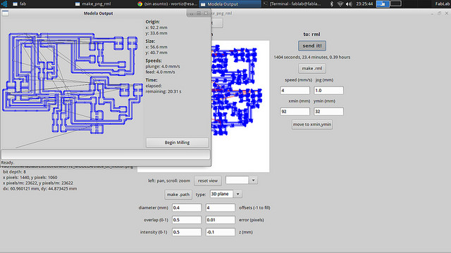
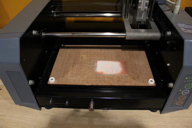
Then, according to the last Electronics Assignments I drill my board
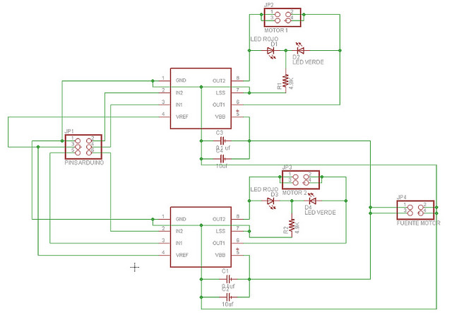
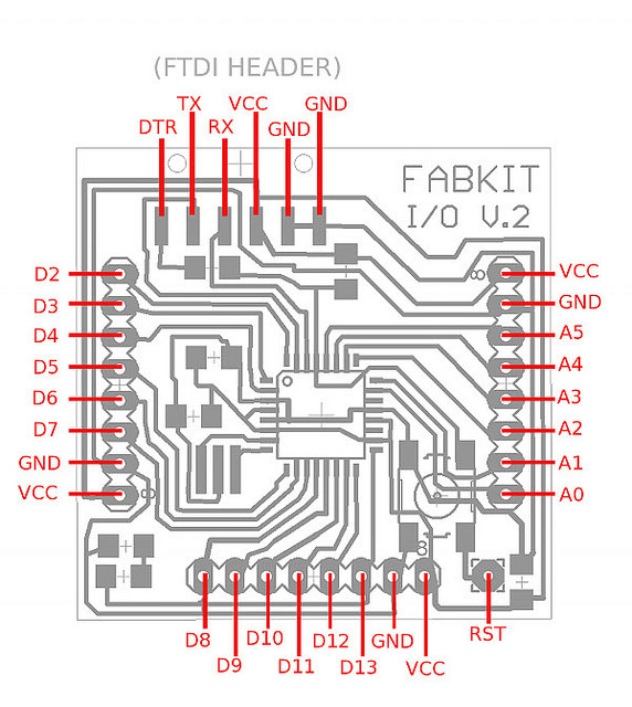
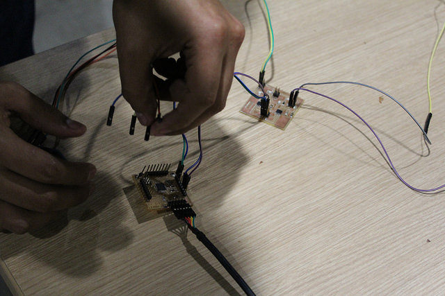
Once soldered my board, I had to program it in Arduino IDE to move my DC motor, for this had to identify which pins of the bridge h go with which pins of the Fabduino.
For this, use the schematic designs of both plates.
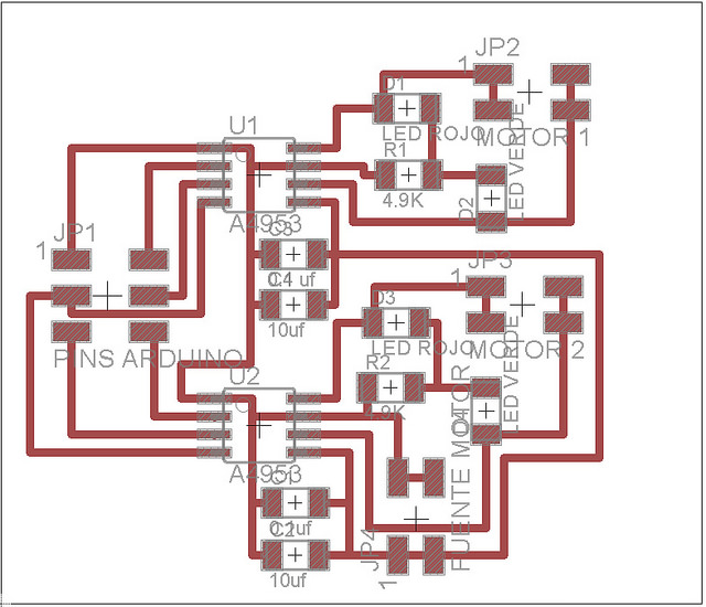
It is very important to know what each pin is and how it should be connected so for the case of the bridge h we consult the data sheet of the A4953
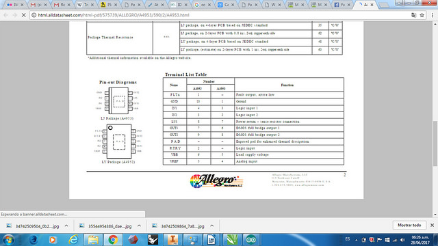
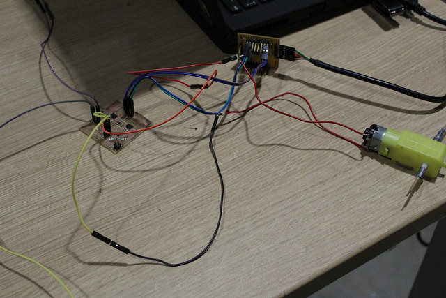
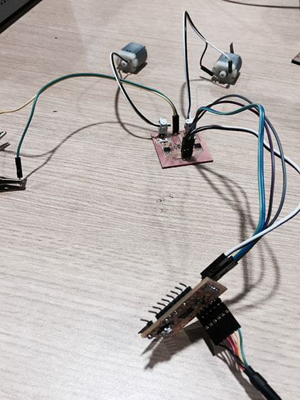
We connect the motor and the source to the bridge h. In this case, it does not matter which of the two bridge pins goes to the motor but for the source you have to be very careful of which is GND and which VCC.
If we are wrong we can burn all our plates and our engine.
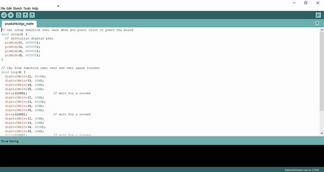
We connect the FTDI cable to Fabduino and open the Arduino IDE and write the order that we want to give the microcontroller.
In this case the code is similar to one of the programming of my Assigment 8 to move a motor. It could easily move two motors since my board has capacity for two motors and the Fabduino has more pins.
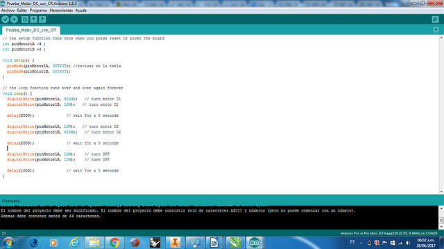
In this case we see that it has been since the pins of the motors are the digital pins 3 and 4 and since the code is binary it means that when the pin 1 of the motor in HIGH turns in one direction for 5 seconds, after this When motor pin 2 is HIGH, it will turn in the other direction for 5 seconds.
We can see it in the attached video:
OTHER PROGRAMMING : Additionally, I wanted to program two motors (DC Motors) to operate at different times, first one to the right, then to the left and then the other to the right and I call to the left. Also you could put a delay time between the movement of each motor but for this example is not considered.
It is important to emphasize that once the two motors rotate according to the programming they will start again and again because that is how the Arduino IDE works.
My h bridge has capacity for two motors, then we can see what the connection is like :
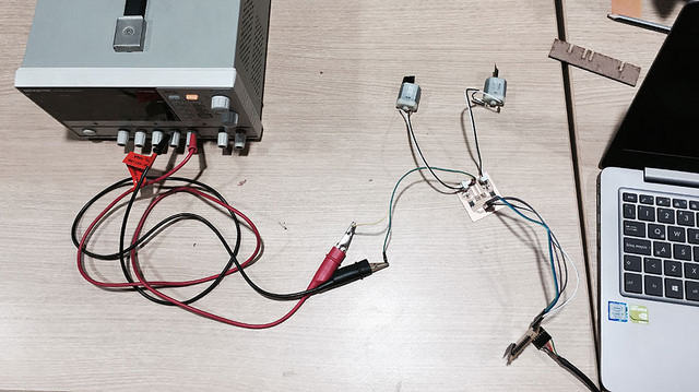
In this case we will use a power supply station but could use a battery or a battery, its energy is sufficient.
Since we are using 4 digital pins of the fabduino (Pin 2,3,4 and 5), we first write them in "Void Setup" to configure what they represent and then in "Void Loop" we write the sequence in which they will do it and the time .