- Week 12 +
molding and casting
Tasks
Concept and Design Development
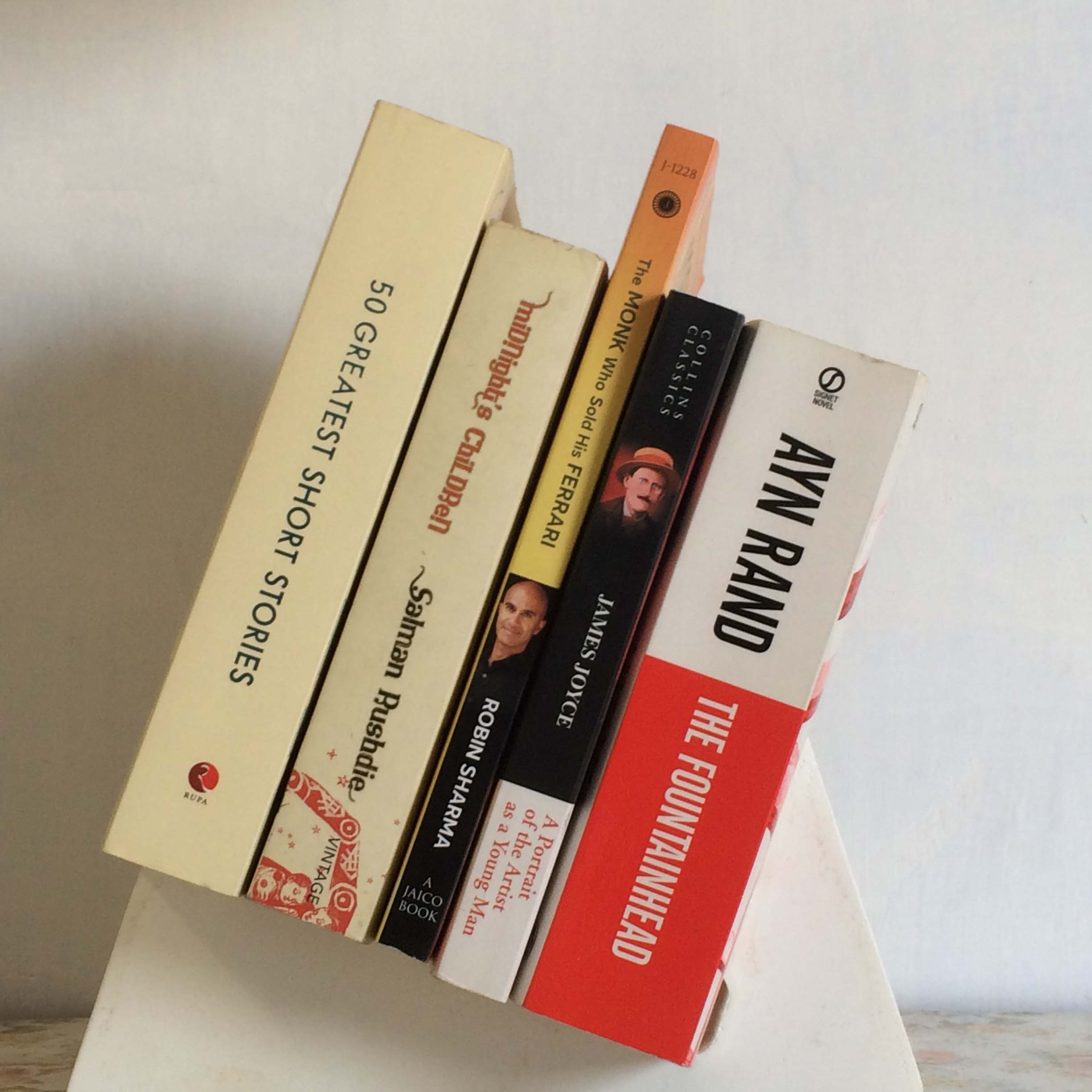
How to stack books properly on a desk?
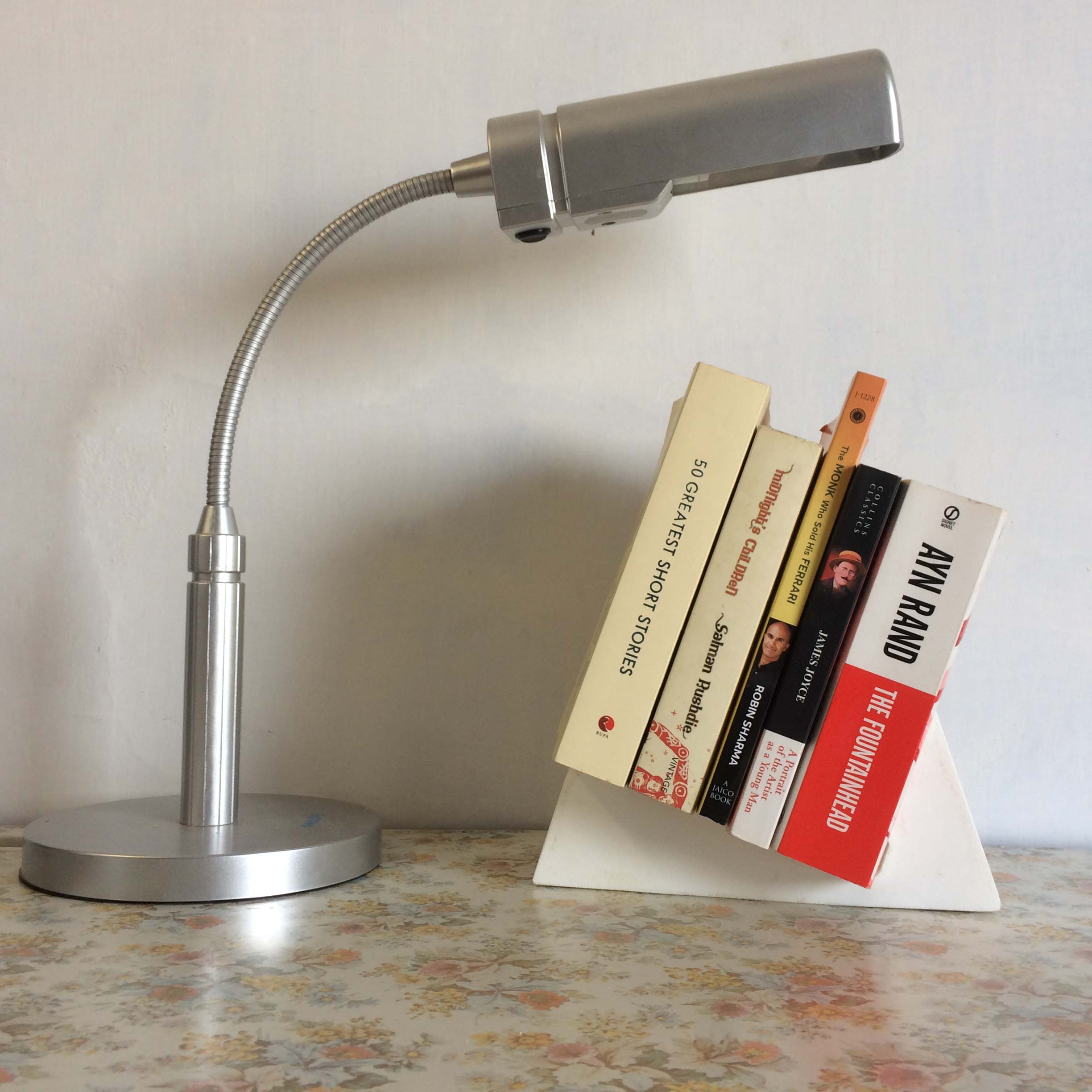
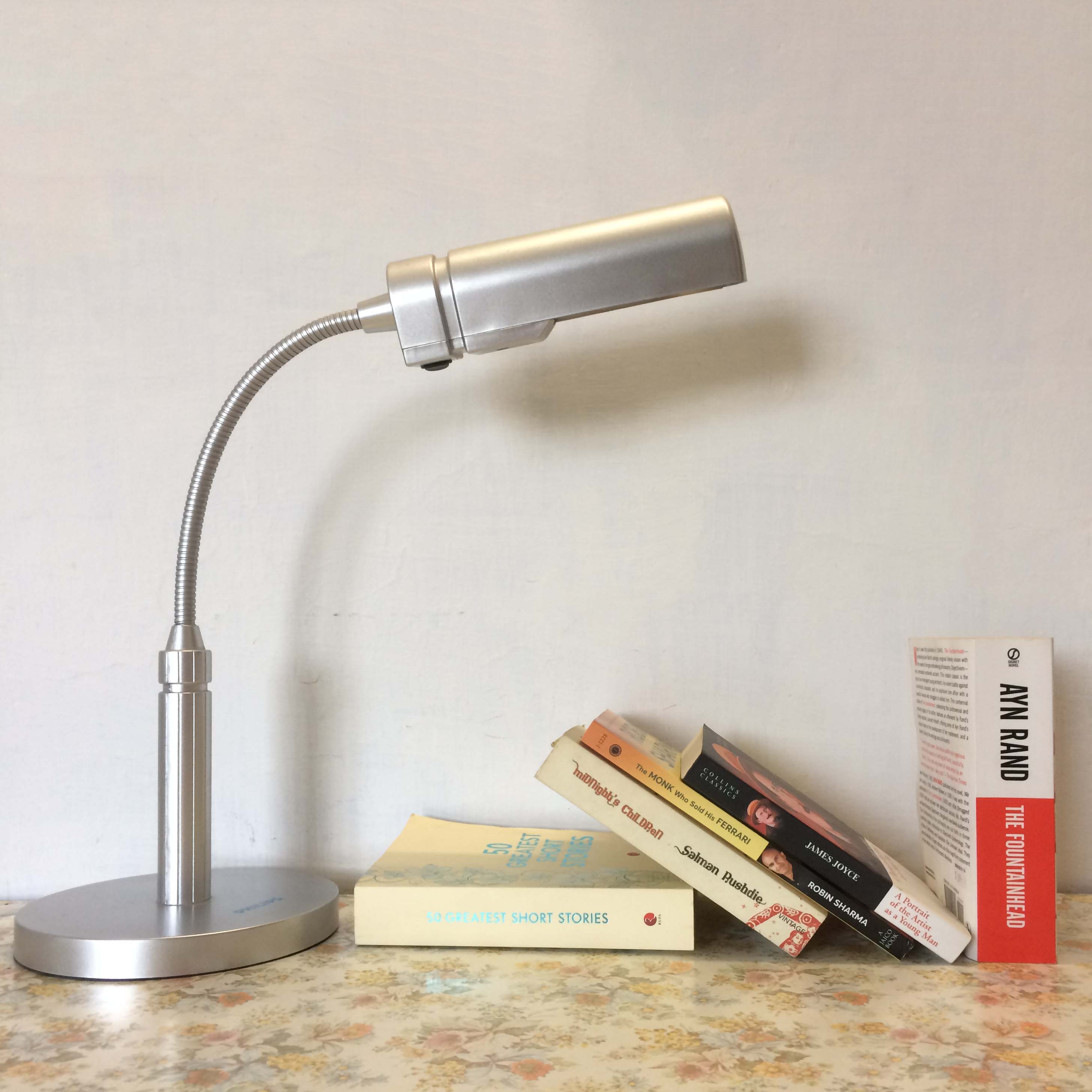
I have a habit of keeping some quick references on my desk, especially novels that I am currently reading. I usually face problems in stacking them properly aligned to each other. If I stack them inclined to the wall, they tend to loose its form atfer some time and become skewed in shape. And in case they are stacked perpendicular to the desk surface the tend to fall back.Its quite evident in the following images.
Solution
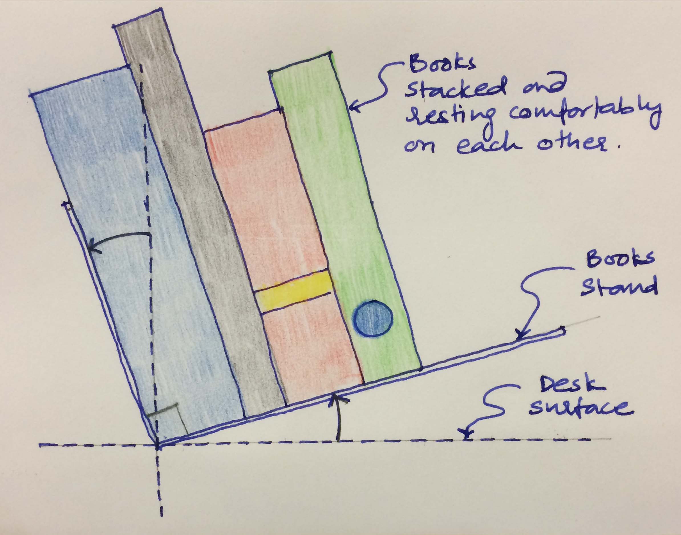
To solve the problem, I decided to cast a small books stacking stand. The idea is to have books stacked at an angle of 20 degrees to the desk surface and align to each other. And a support at an angle of 110 degrees desk (90 degrees from the surface which is 20 degrees from the desk surface). Sketch below gives an idea of what I imagined.
Drawing
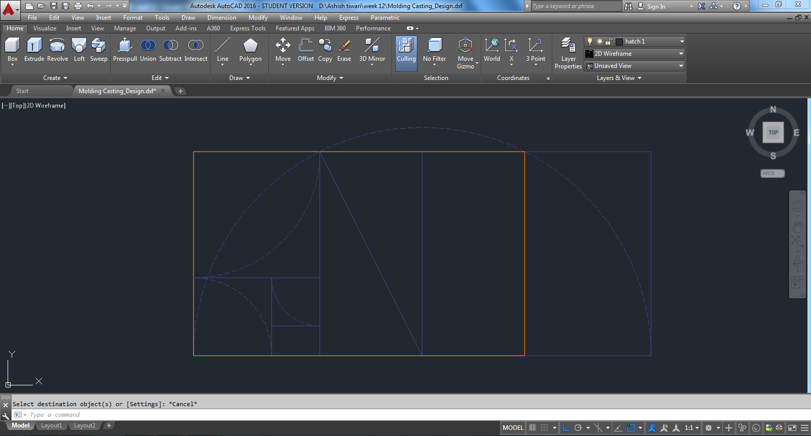
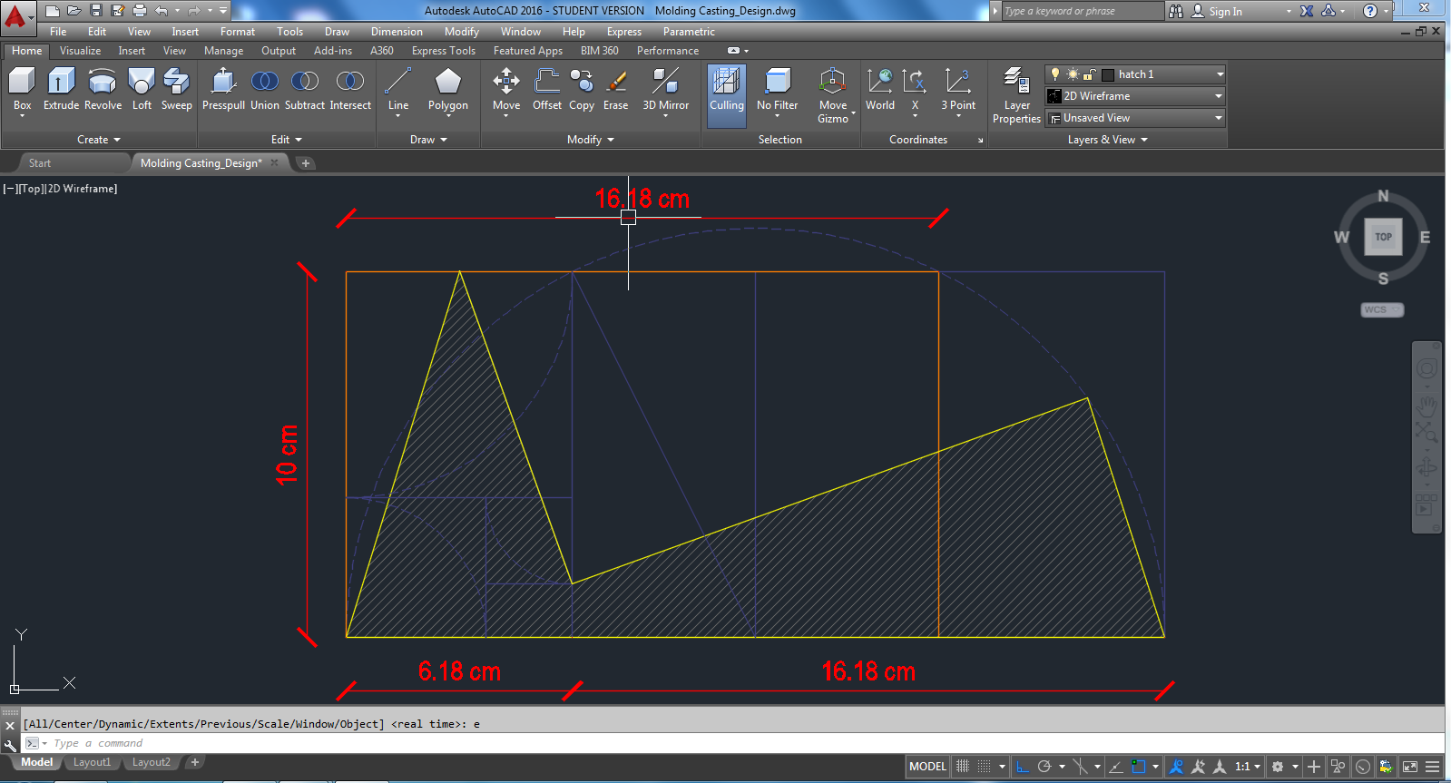
At first, I decided to draw 2D profile of the stand I wanted to cast. I thought of deriving the profile using Golden Ratio. I used the tradition geometric method to draw it in AutoCad. The golden rectangle I drew has its shorter dimension of 10 cms. Below screenshot shows the rectangle in orange.
Now, to get longer surface to accomodate more books I added additional length of 6.18 cm to it to maintain the ratio. It was achieved my extending the arc further on the other side. It can be seen in the screenshot below.
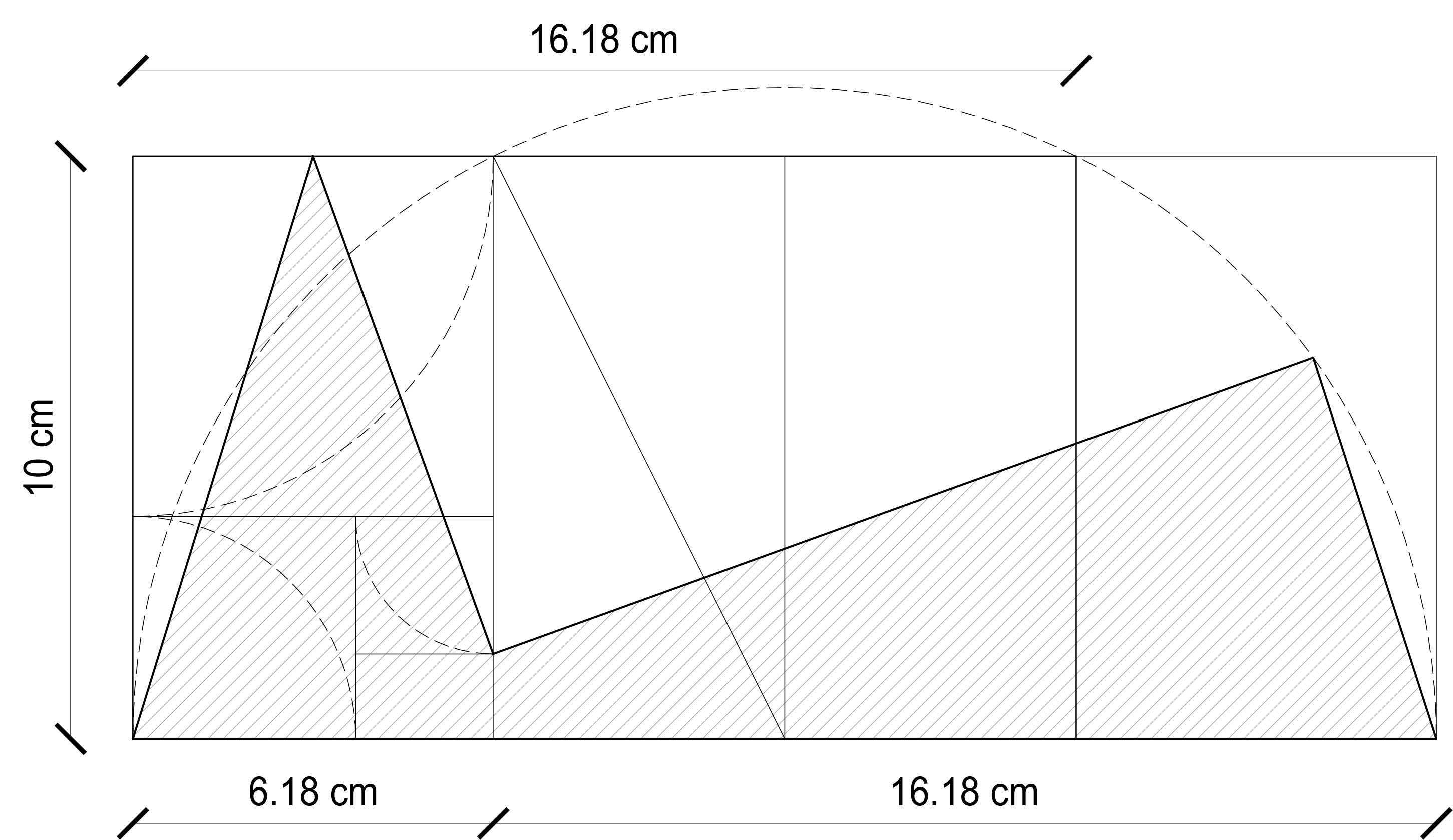
Finally, what I get is seen as shaded area in the image below. So the shaded part is what I will be casting. It is the face of the mold. It is what I will see in elevation too.
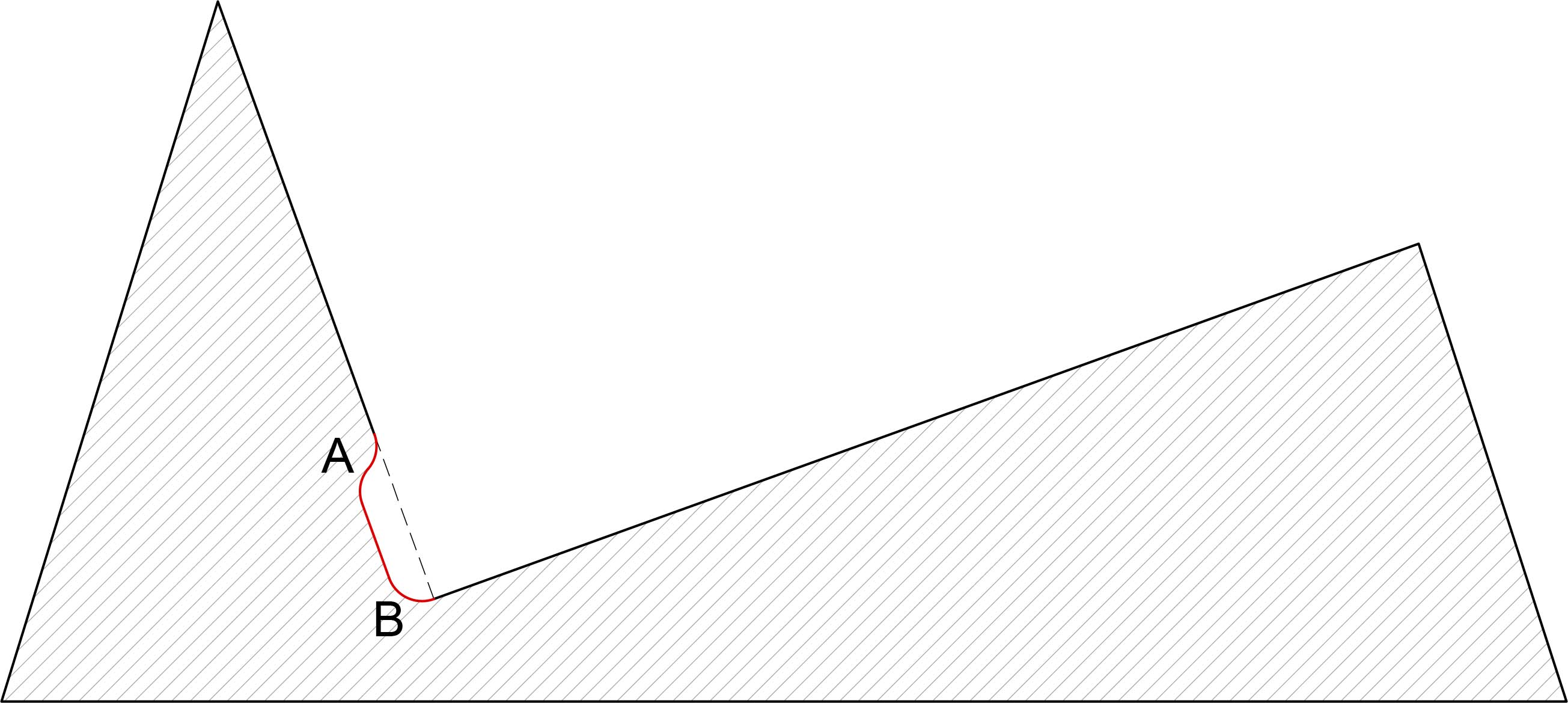
Now, to achieve inside inclined surfaces to be exactly perpendicular to each other I had to make some modifications highlighted in red in the image below. This modification for inside cut allowed me to accomodate commensurate radius of the drill bit I will be using for milling. Also, pulling apart curve A and B by 20 mm would help me to remove the mold easily.
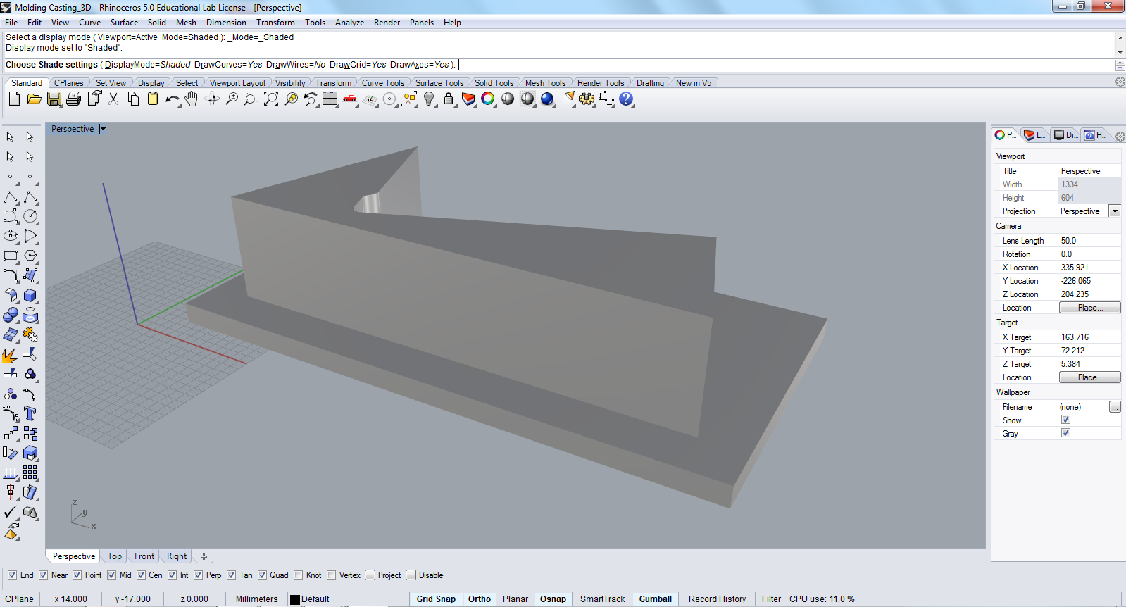
Giving some depth to the profile is the next step. To do so, I used extrusion command in rhino. The depth/ thickness of the books stand could be anything between 3cms to 5cms. I choose to make mold for the higher limit, so that I could cast any thickness upto 5cms. 3D file below gives a fair idea of how it will look eventually.
Process 1-CNC Machining
Toolpath
First thing that I did was, I opened the 3D model in PartWorks, and the initiated the process of setting up the parameters for CNC milling. In Orientate and Size Model section, I defined the correct orientation of the model to be milling. Then in the material size and margin section I defined the origin point, the depth of the model from the top surface and the bottom surface of the model. Then came the three toolpaths- roughing, finishing and cut out. I created only Roughing toolpath and finishing toolpath as I wanted to keep the base for creating base for rubber mold, when it is poured. Following are the parameters I gave:
Roughing Toolpath
Finishing Toolpath: Key parameters in the finishing toolpath are-
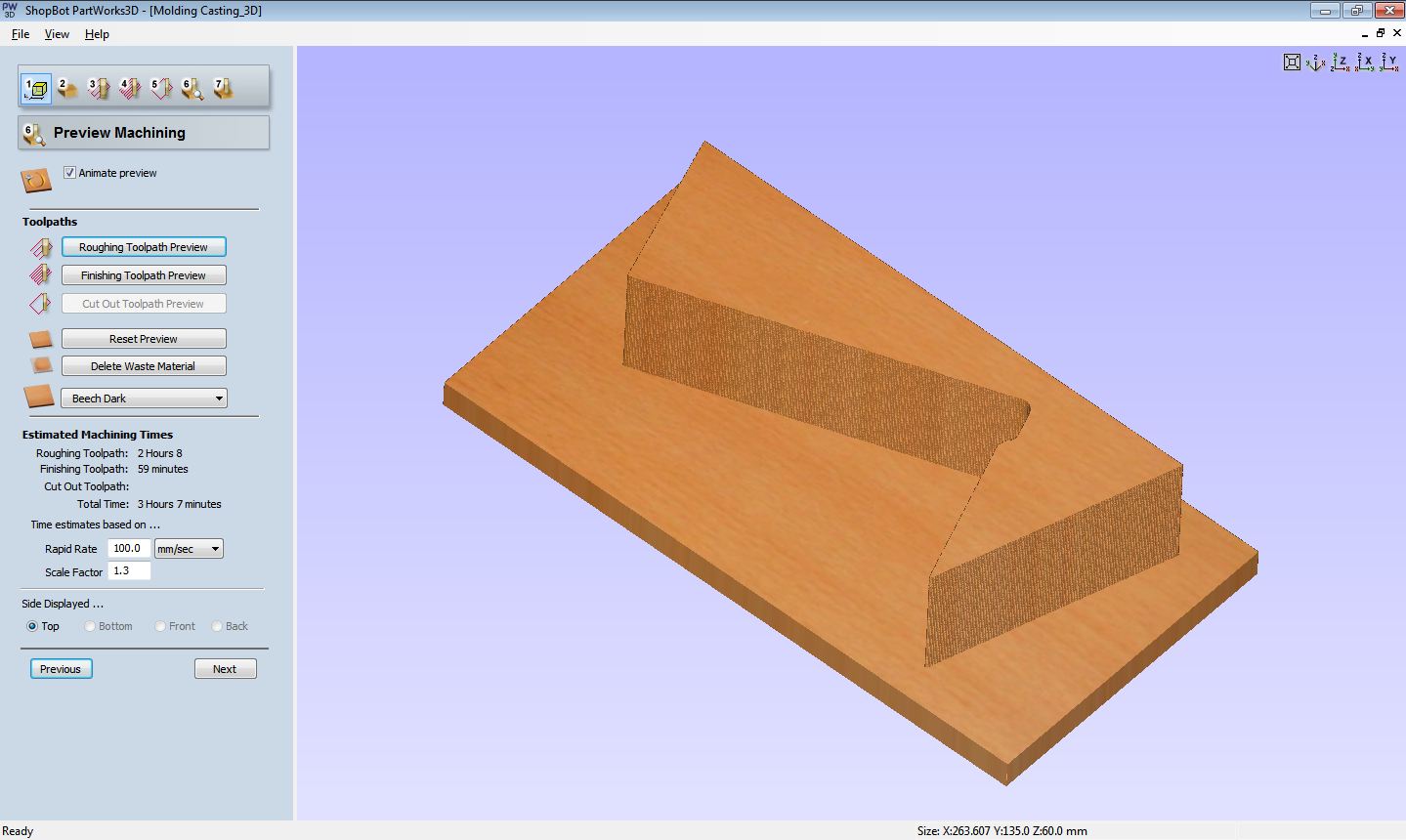
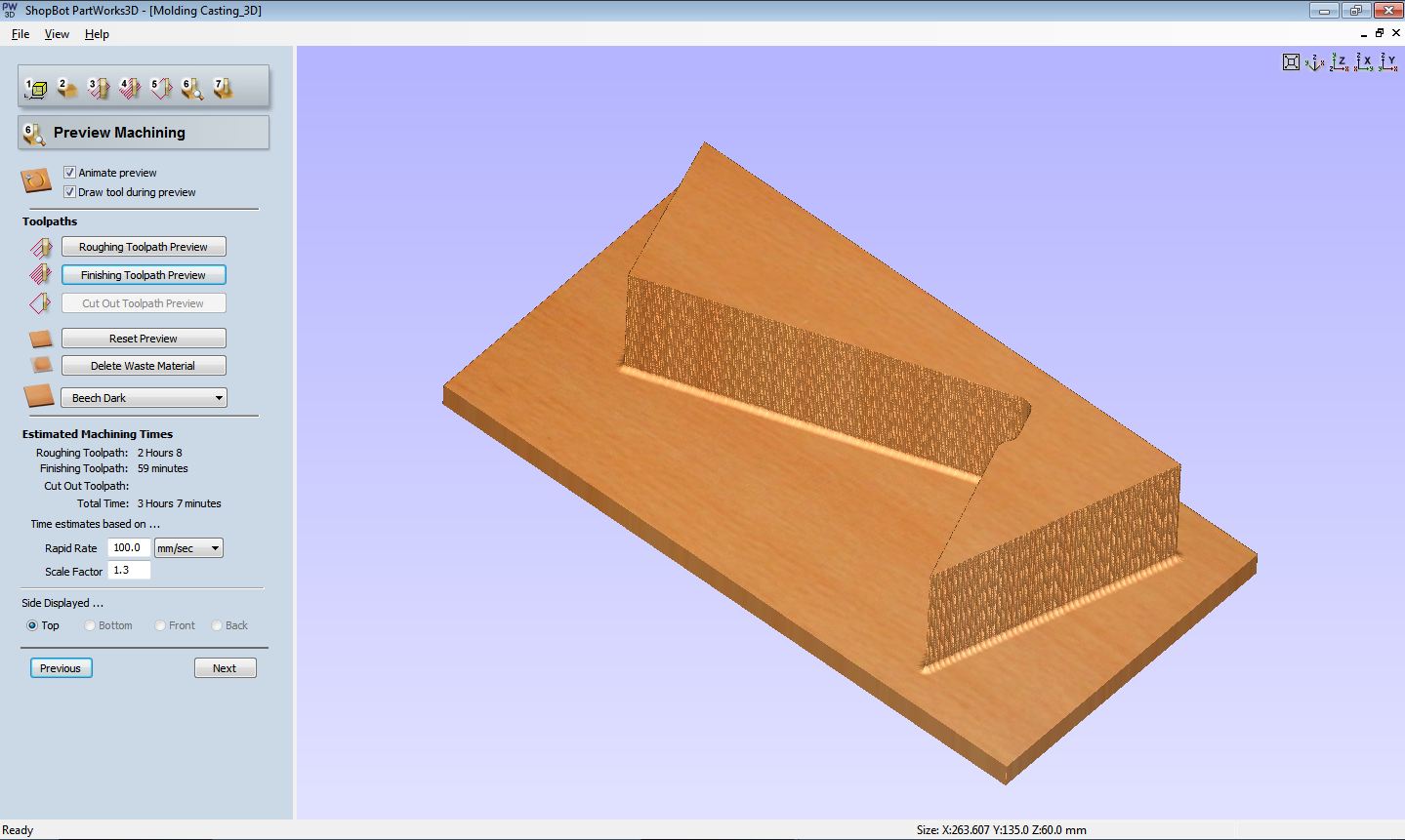
Preview Machining: Here I did the simulation of roughing and finishing toolpath to ensure everything is in place.
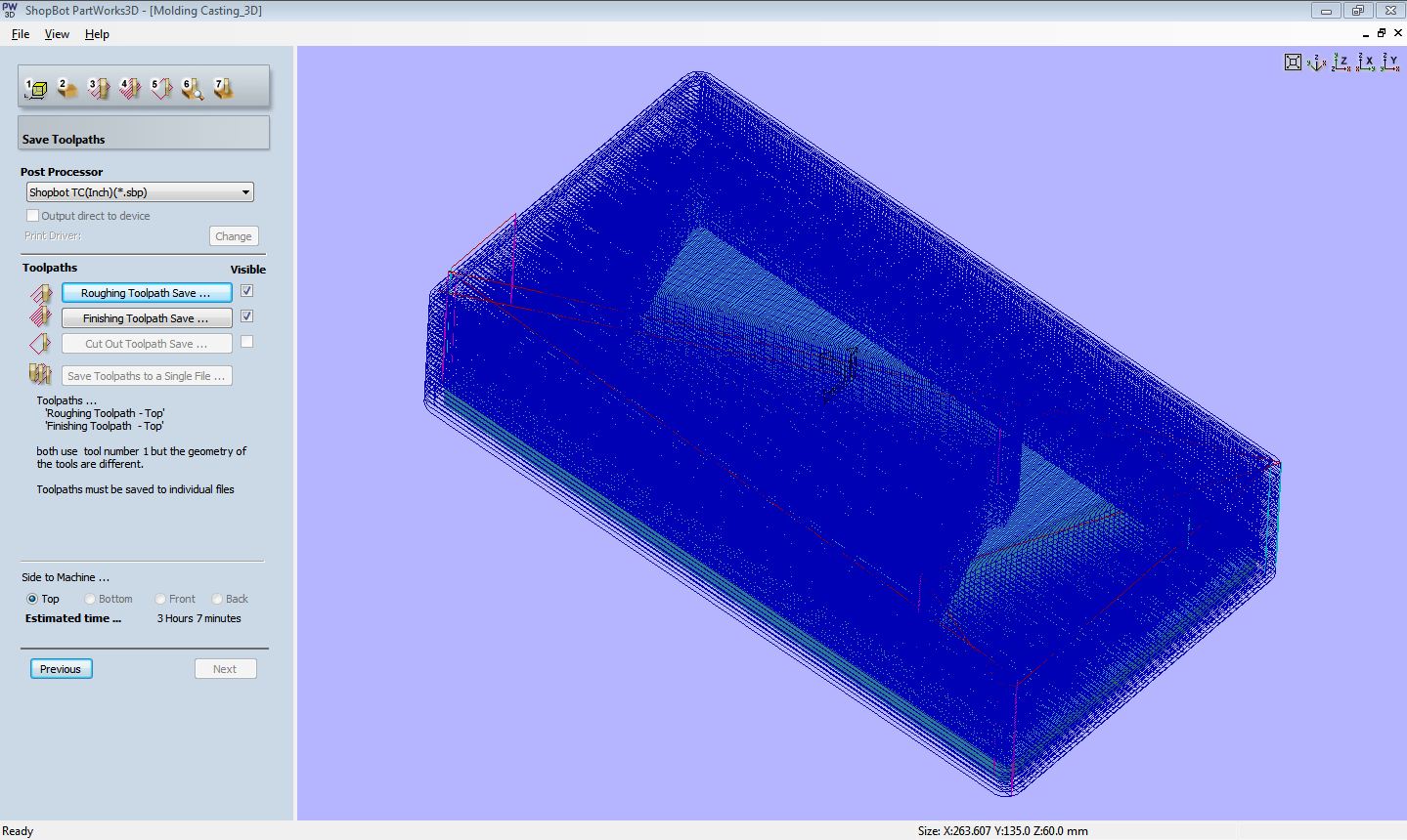
Save Toolpaths: Here I saved the toolpaths in .sbp format which is good for milling. The estimated projected time it showed was 3hrs 7mins.
Milling
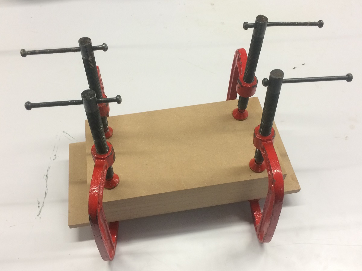
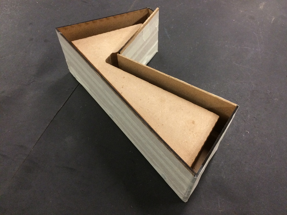
For the purpose of 3D milling, I decided to create my own material for milling such a deep (in z-axis) object. As getting a solid piece of wood would be very expensive, I settled for some scrape MDF we have in our lab. I used it to create the milling material. Then I mounted it on the sacrifice board and hit the start button for milling to happen. But, in just one go, I realised that the milling has some issues as there were horizontal mill grooves that started to form. I immediately pressed stopped button. Later I realised that the orientation of the material was wrong. Since, its a cuboid and not a cube I should have ensured that the material is mounted in the right orientation. I corrected it and started the milling again. This time it came out exatly what I wanted. The slit could be seen in the video below on the top surface.
Process 2-Molding
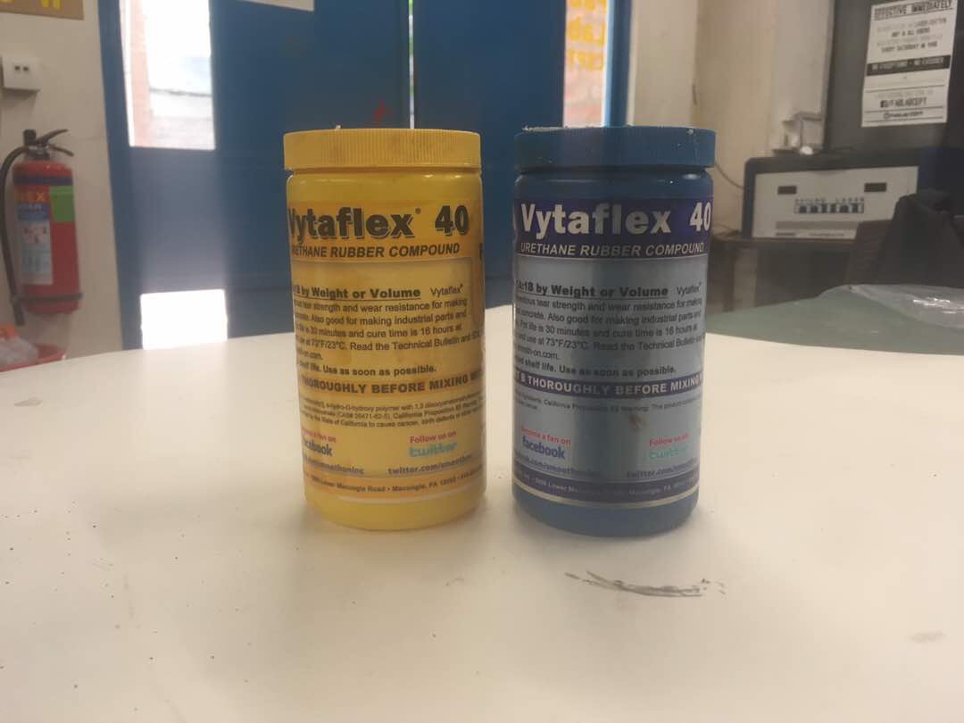
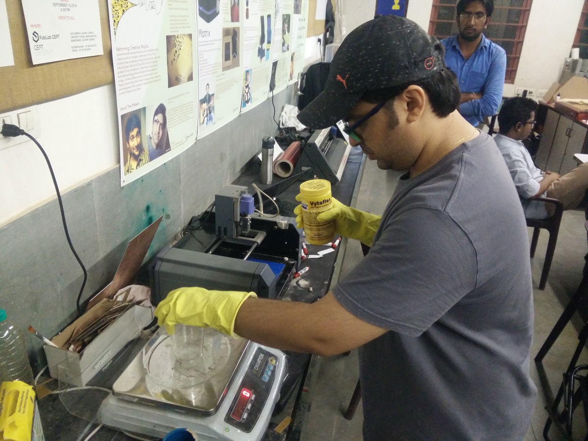
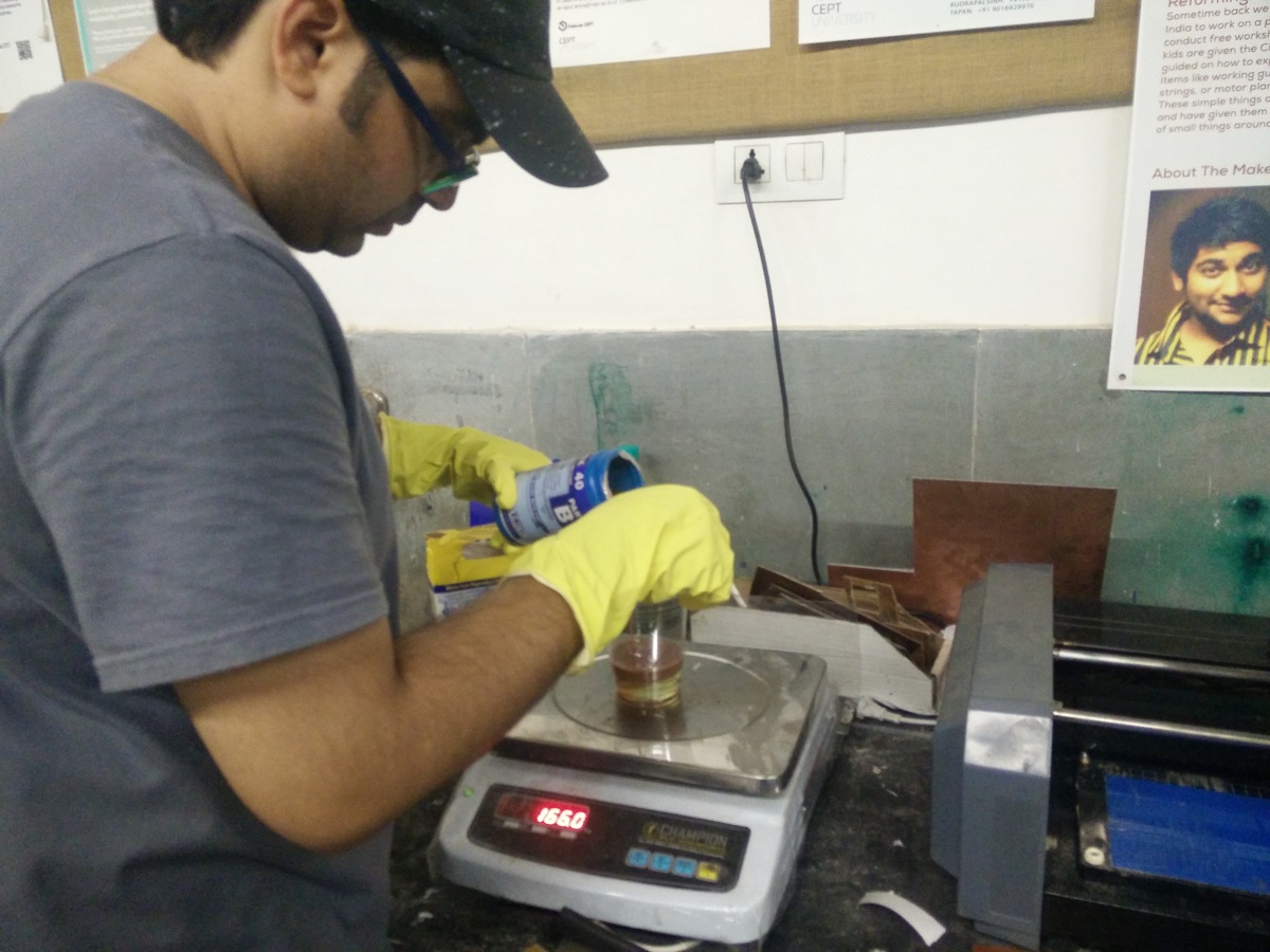
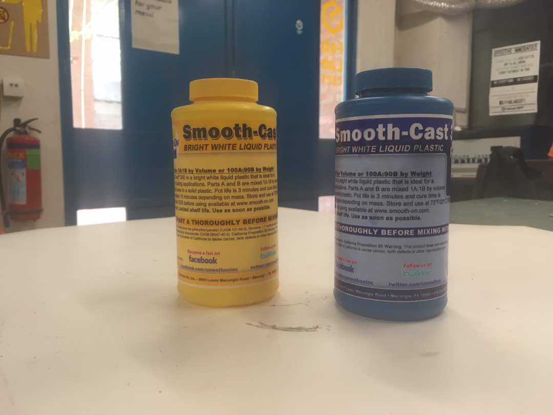
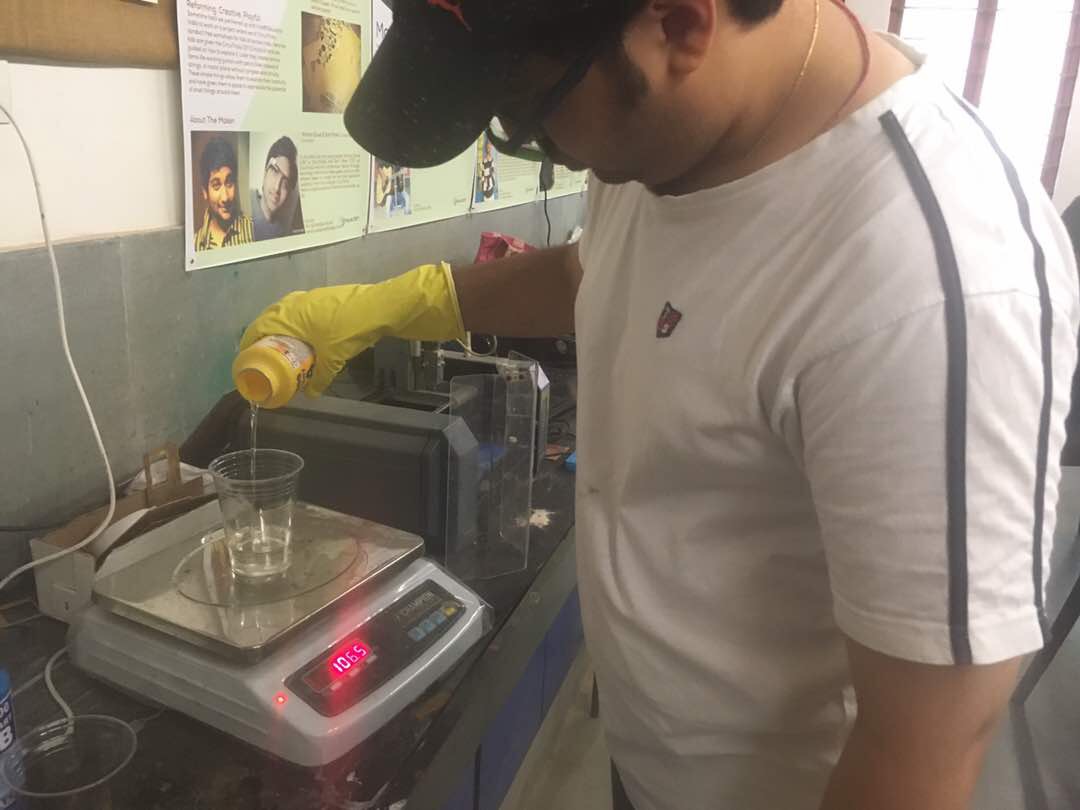
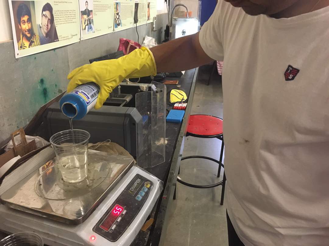
To make the rubber mold, the first step is to zero the scale after putting the glass I will be using for the mixture. I am using Vytaflex 40 Urethane Rubber compound to make rubber mold, which actully is a negative mold.
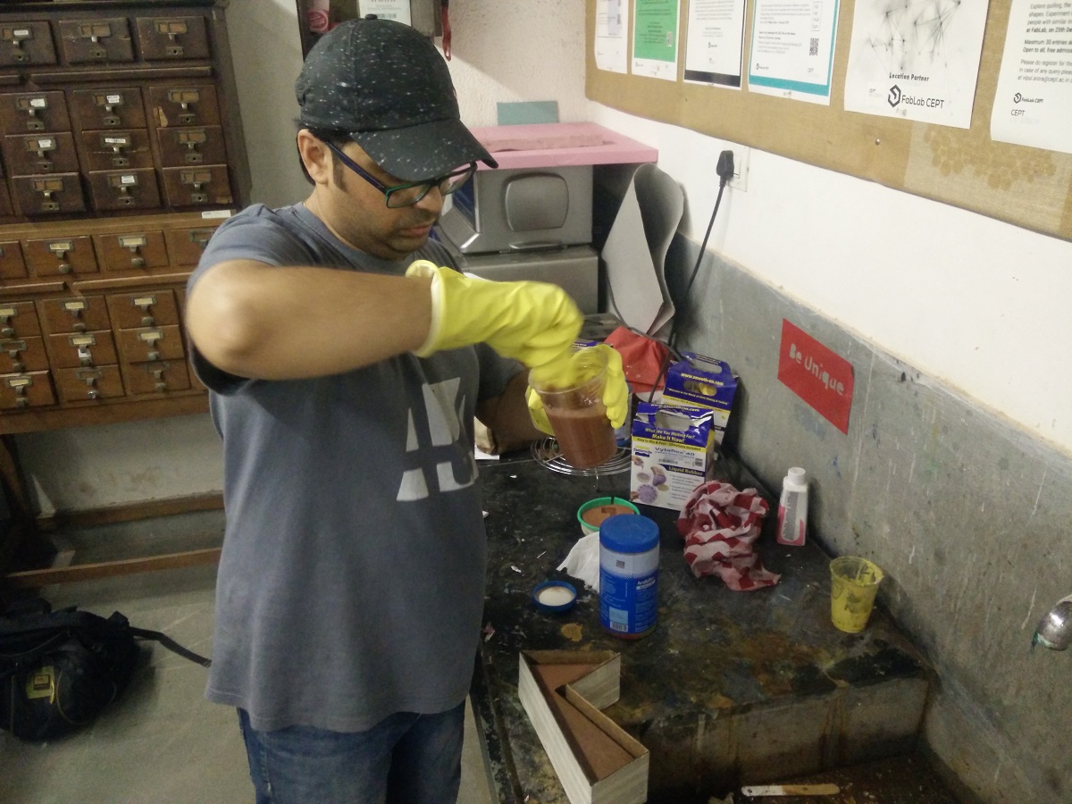
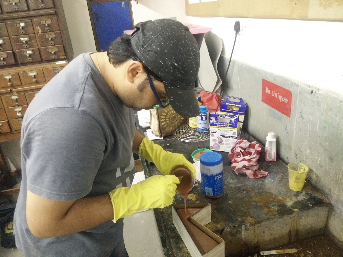
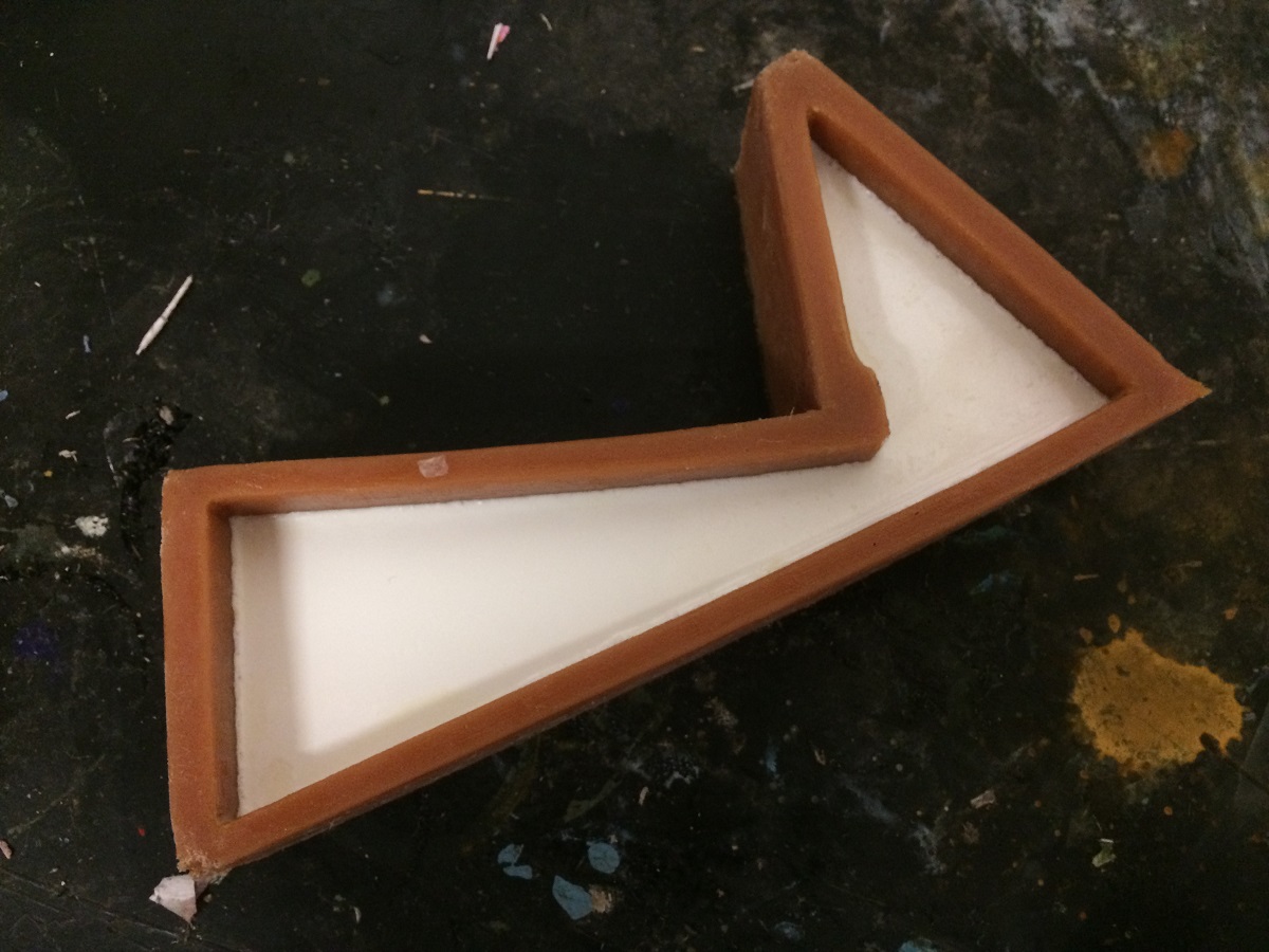
Process 3-Casting
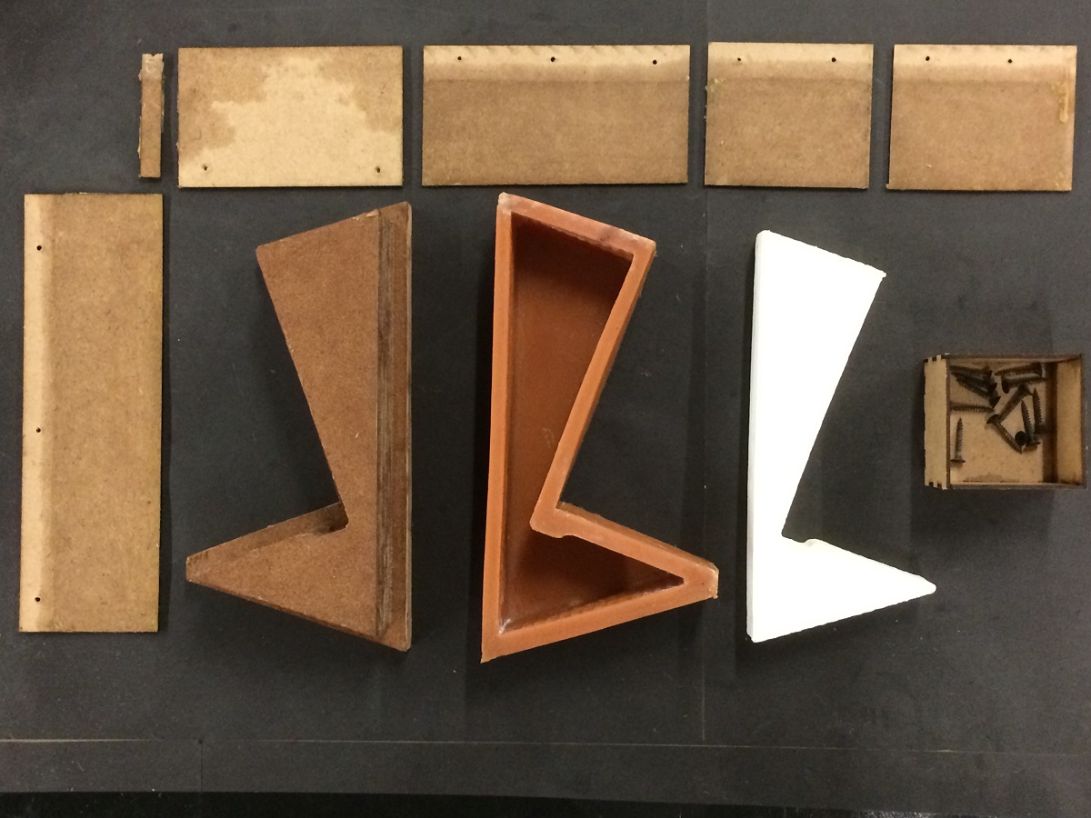
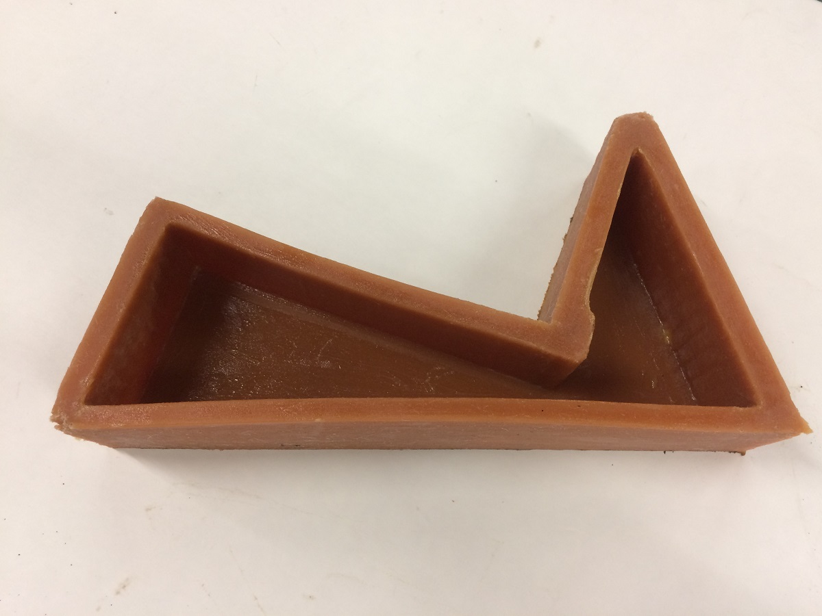
Final Object
Links
Week 12 FilesSketchfab
PartWorks
Shopbot Tutorial