- Week 11 +
mechanical design and machine design
Tasks
Make a machine, including the end effector, build the passive parts and operate it manually
Automate your machine. Document the group project and your individual contribution
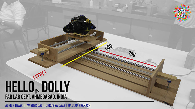
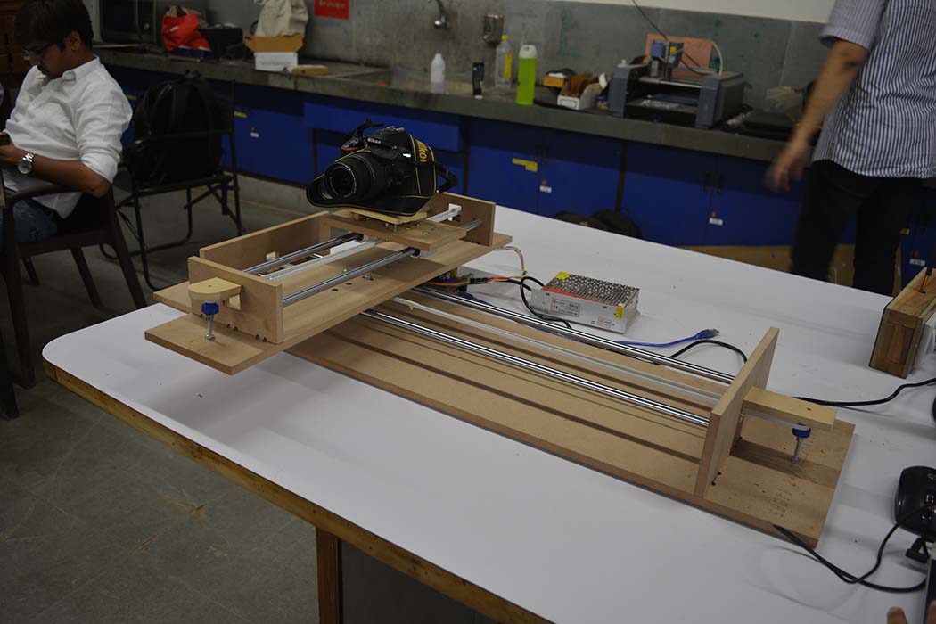
Idea
We wanted to improve our documentation and make taking photographs easy and automatic. Hence, after a lot of brainstorming, we came up with this design for a camera dolly.
Team
Avishek | Gautam | Dhruv | Me
Work distribution
We divided ourselves into pairs of two. I and Avishek were handling design, detailing and production. I specifically took care of entire production of the camera dolly. For the first week we made mechanical parts largely using laser cutting machine. And assembled all the components for seeing its working. Dhruv and Gautam handled electonics and programming.
My thoughts and contributions
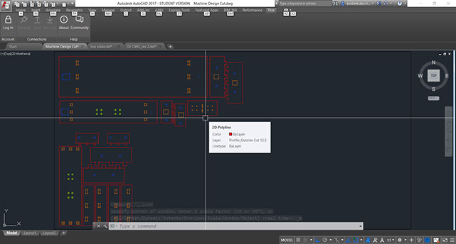
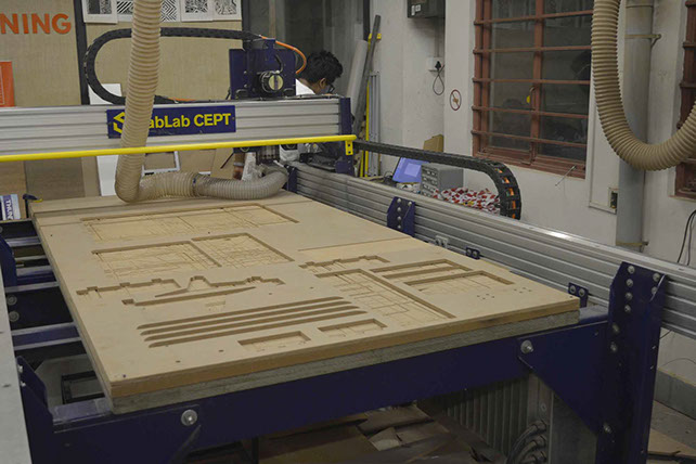
- My contributions were mainly in design overview and validation and managing the design workflow. I also produced drawings for milling on the ShopBot and prepared toolpaths for the same and milled the frame/base.
- I also did the assembly of the mechanical design.
- In terms of learnings, we realized that system integration (bringing together different systems to compile the machine) requires a lot of forethought.
- Taking this further, we must improve the camera mounting adapter design, replace the current belt with rubber GT2 timing belt
- But my most important contribution was the fact that I made the demo video look good by being a good static model :D
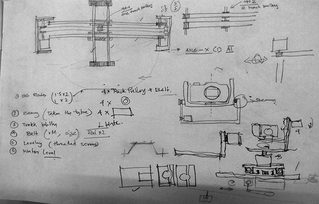
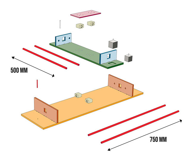
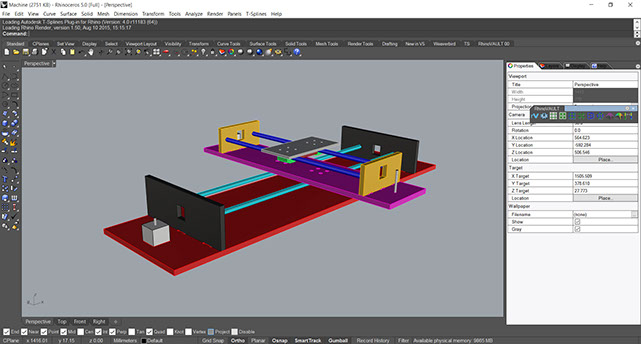
Design
Fabrication and Assembly
Final Object
Process
My understanding of the software workflow

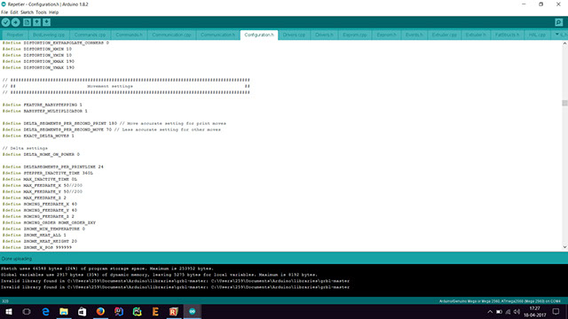
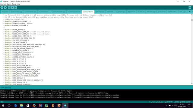
- The marlin firmware resides in the Arduino-mega
- The RAMPS shield allows connections to upto 4 stepper motors, as it has 4 stepper drivers with heat sinks
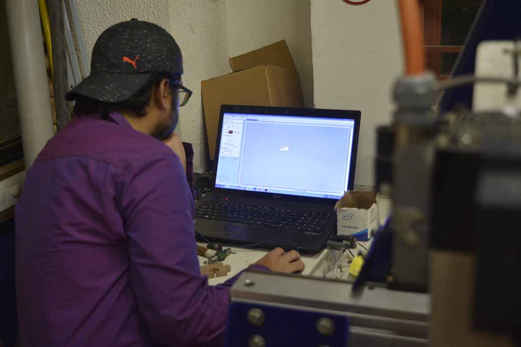
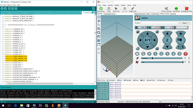
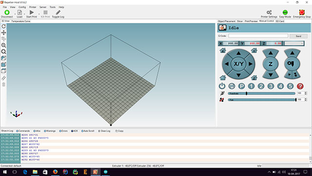
- The Repetier host provides the UI from a host computer
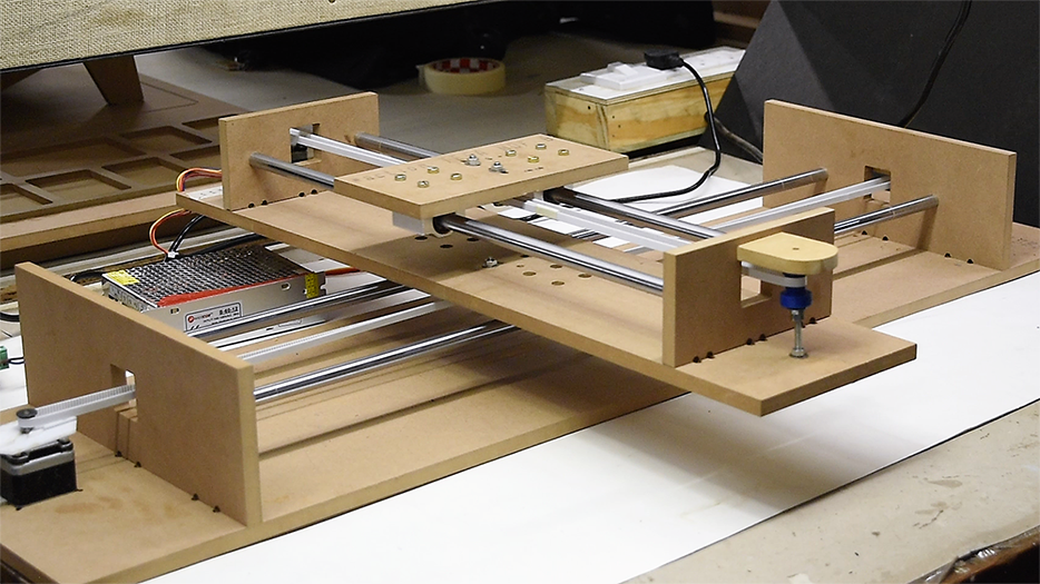
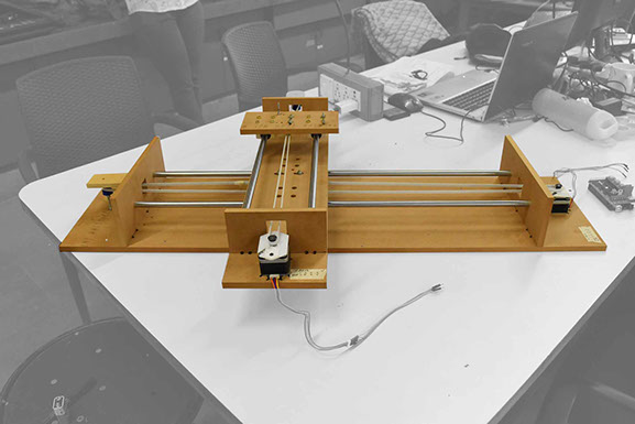
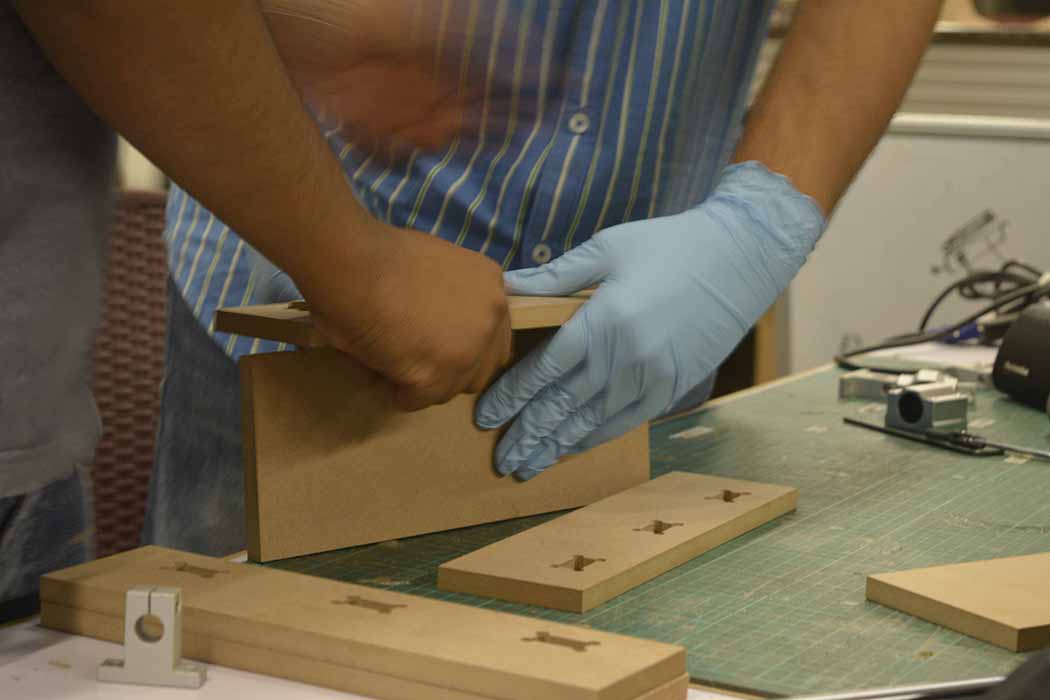
Initial prototype of mechanism
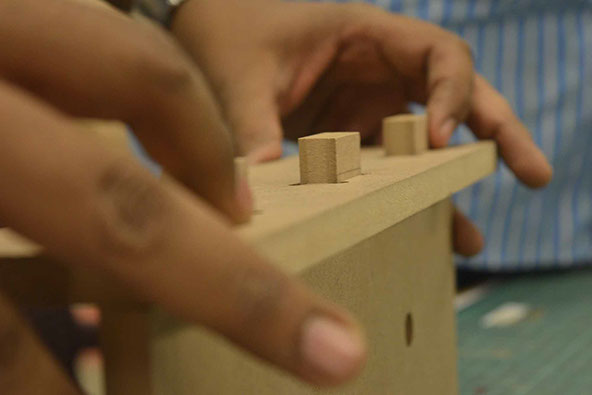
We fabricated a basic version of the mechanism to test the hardware's tolerances and gives., it helped us foresee problems we might face in the final CNCed version
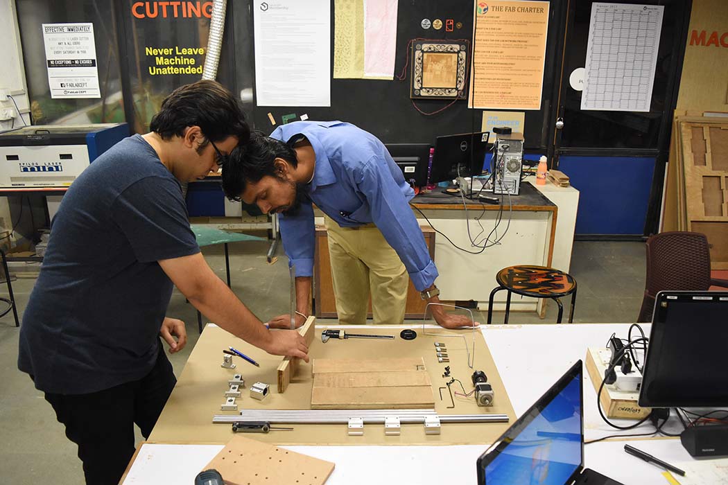
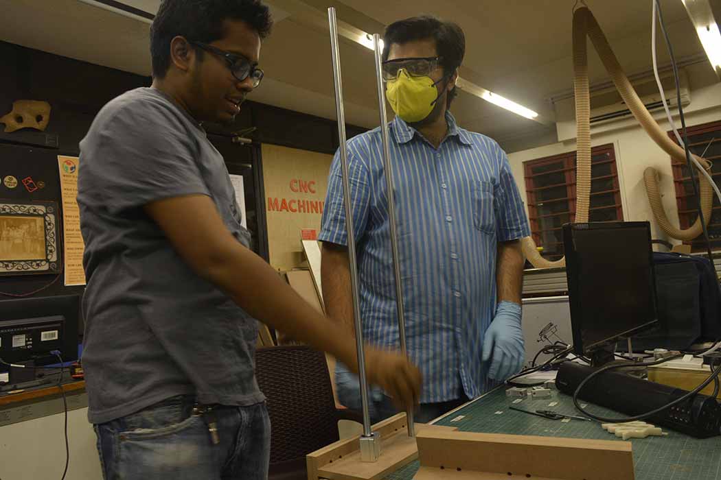
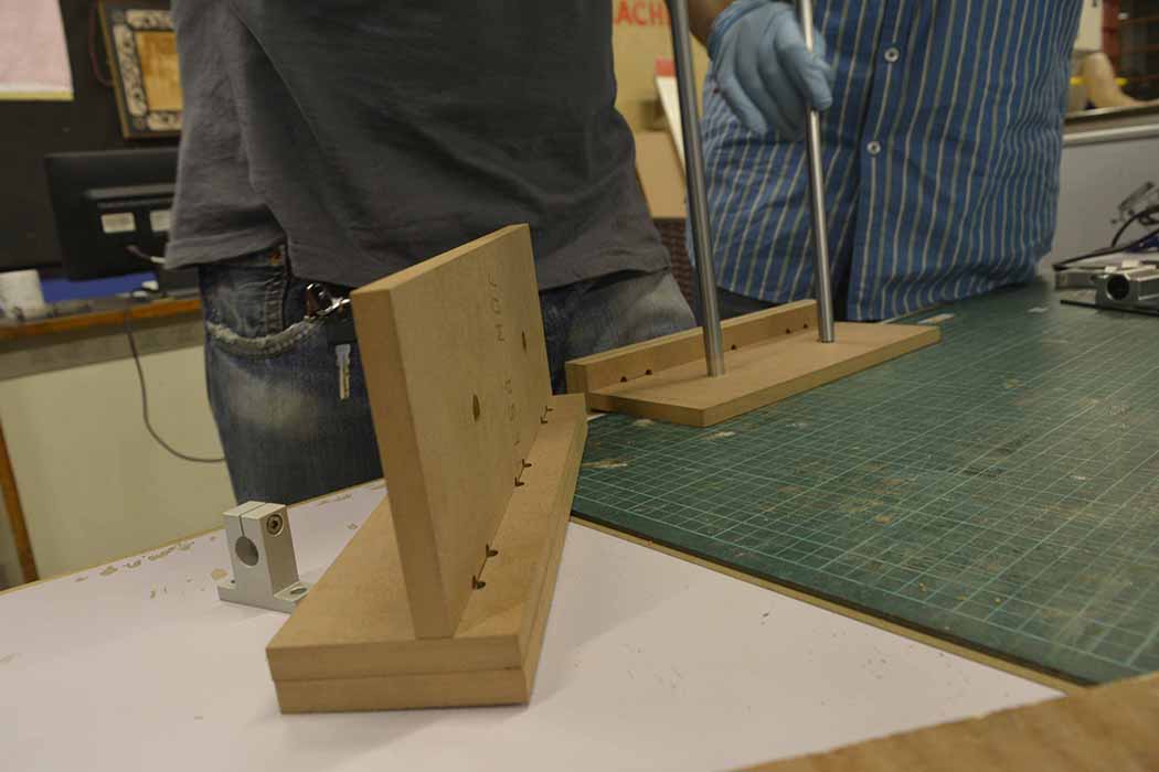
Us - trying to test the strength of the joint
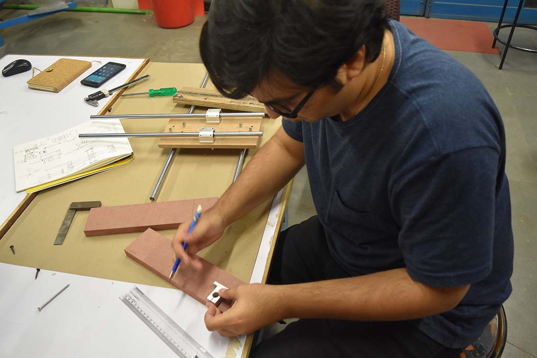
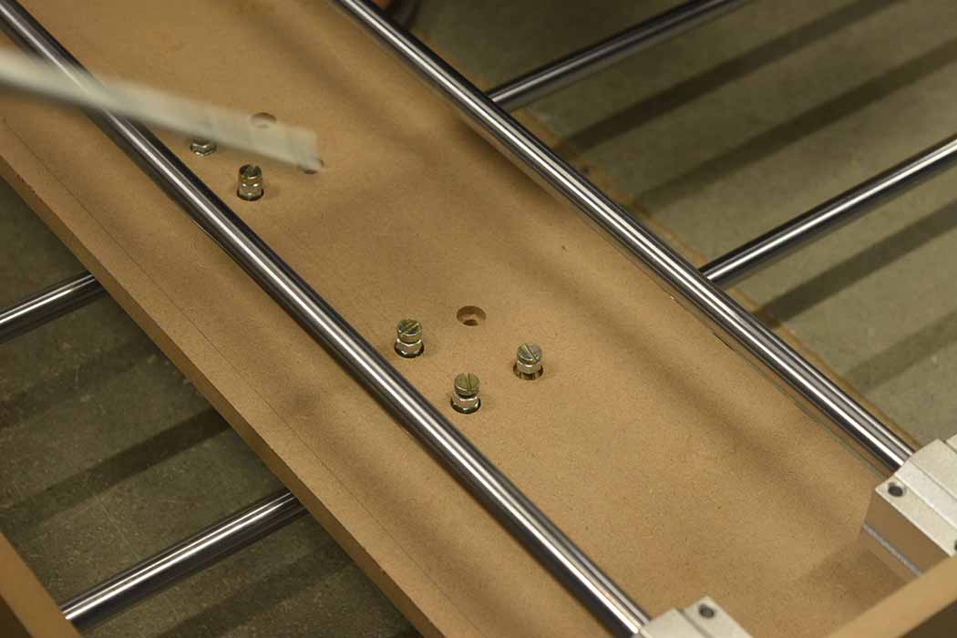
It also helped us in finalising proportions and key dimensions of the 2 axes.
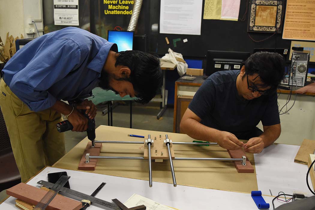
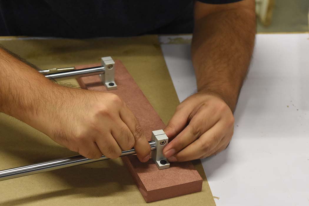
It was essential that these parts were as orthogonal as possible for smooth movement
Components
| Component | Origins |
|---|---|
| CNC frame | Digitally fabricated |
| Hardware - Bearings / Smooth rods | Local vendor, but accommodated in our digital designs :/ |
| Pulley | Digitally fabricated (3D print) |
| Timing belt | local vendor |
Video
Detailed documentation on Group page
Links / Downloads / Code
Week 9 and week 11 DocumentationMachine-week.zip
The above zip file contains the following-
- DXF files for CNC machined frame
- STL Belt holder to be 3D printed
- STL Belt holder version 2
- .GCODE for the same
- .3DM files are Rhino designs
Repetier Host