Embedded Programming programming the Atmel micro controller
This week it it is all about learning to write code for the microcontroller board we designed two weeks ago. Because of the board limitations with one led and one button I later switched to a ATmeta328 board to use its hardware UART for testing the serial communication. But lets start with the hello board I designed and check if it works as it should.

This is the second revision of the board I created in week 6 in the fabacademy. If you are interested visit the link below to see how I created it.
Setup the toolchain install the necessary software
Software I used my toolkit
Atmel Studio
Atmel Studio is from the microchip manufactor Atmel itself. It is an all in one IDE for working with Atmel microcontroller. It has the whole library of the Atmel products installed and delivers all the information about the microcontroller like data-sheets.
AVR Dude
AVR Dude is a command line tool for all operating systems so manipulate the flash memory of the Atmel microcontroller. AVR Dude it can be used to flash microcontroller on the command line of my mac.
hterm
hterm is a serial communication frontend that is able to visualize the serial data that can be receive with a TTL cable. It can be installed on Windows and Linux.
Using AVR Dude working on my mac.
To start with something I was familiar from the board designing week I come back to visit AVR Dude to update my demo program from the last time. First I updated my code. to tell the software that I want to use my external crystal that runs on 16MHz. I not set the fuses on the chip yet but that will be the next step.
After that I define three macros that help me later in the code. With the macros defined the code is better readable and I don't have to deal with the bit shifting all the time. So I write a macro that check for the PA3 pin and read the value from it. The next two lines are shortcuts for turning the LED on pin PA0 on and off.
Then I write a small function that let the LED link every second. Thats because I want to check with my clock if the LED is blinking every second. So I can check if the clock of my microcontroller is working right.
Then I setup my port register to configure the input and output pin for my button and LED. I also setup the internal pullup resistor that was not necessary because I also used a external one.
Last I updated the loop and check every time if the button is pressed. If so, the LED will brink in its predefined pattern.
/*blink.c
 * AtTiny84 Blink
 * Created: 21.03.2017 14:42:02
 * Author : Florian
 */

#include <avr/io.h>
#include <util/delay.h>

#define F_CPU 16000000
#define BUTTON_PRESSED  !(PINA & (1<<PA3))      // check for button press
#define LED_ON  PORTA |= (1 << PA0)         // turn LED on code
#define LED_OFF PORTA &= ~(1<< PA0)         // turn LED off code

typedef unsigned char  BYTE;
typedef unsigned short WORD;

void signal(){
    LED_ON;
    _delay_ms(500);
    LED_OFF;
    _delay_ms(500);
    LED_ON;
    _delay_ms(500);
    LED_OFF;
    _delay_ms(500);
    LED_ON;
    _delay_ms(500);
    LED_OFF;
    _delay_ms(500);
}

int main (void) {
    // declare PA0 as output pin. This is where the motor and LED is connected
    DDRA = (1 << PA0);
    DDRA |= (0 << DDA3);    // using A3 as button input
    PORTA |= (0 << PA3);    // pull-up resistor


    // main loop
    while (1) {

        if (!BUTTON_PRESSED){
           signal();
        }

    }
    return 1;
}
After flashing the code with my makefile to the chip with make flash the board do what It should. But the LED was blinking very slow as expected because the chip still runs on its internal clock and on top the divide by 8 fuse is set that it is resulting in a 1MHz clock instead of 16MHz.
Because AVR Dude read the current fuse settings for me when flashing. I was able to study the fuses that where set as standard. I changed the high low and extended register to their use an external crystal from 8-x MHz and also delete the divide by 8 bit.
# Makefile
#
# Straight forward makefile to flash the ATtiny84 and its fuses
# with AVR Dude that blinks an LED.

DEVICE      = attiny84
CLOCK      = 16000000
PROGRAMMER = avrisp2
OBJECTS    = main.o

# FUSES configuration
FUSES       = -U lfuse:w:0xff:m -U hfuse:w:0xdf:m -U efuse:w:0xff:m

# Tune the lines below only if you know what you are doing:
AVRDUDE = avrdude -c $(PROGRAMMER) -p $(DEVICE)
COMPILE = avr-gcc -Wall -Os -DF_CPU=$(CLOCK) -mmcu=$(DEVICE)

# symbolic targets:
all:  main.hex

.c.o:
    $(COMPILE) -c $< -o $@

.S.o:
    $(COMPILE) -x assembler-with-cpp -c $< -o $@
# "-x assembler-with-cpp" should not be necessary since this is the default
# file type for the .S (with capital S) extension. However, upper case
# characters are not always preserved on Windows. To ensure WinAVR
# compatibility define the file type manually.

.c.s:
    $(COMPILE) -S $< -o $@

flash:  all
    $(AVRDUDE) -U flash:w:main.hex:i

fuse:
    $(AVRDUDE) $(FUSES)

# Xcode uses the Makefile targets "", "clean" and "install"
install: flash fuse

# if you use a bootloader, change the command below appropriately:
load: all
    bootloadHID main.hex

clean:
    rm -f main.hex main.elf $(OBJECTS)

# file targets:
main.elf: $(OBJECTS)
    $(COMPILE) -o main.elf $(OBJECTS)

main.hex: main.elf
    rm -f main.hex
    avr-objcopy -j .text -j .data -O ihex main.elf main.hex
    avr-size --format=avr --mcu=$(DEVICE) main.elf
# If you have an EEPROM section, you must also create a hex file for the
# EEPROM and add it to the "flash" target.

# Targets for code debugging and analysis:
disasm: main.elf
    avr-objdump -d main.elf

cpp:
    $(COMPILE) -E main.c
Reading the datasheet explains how to calculate the fuses. In the makefile there is a line where the fuses can be set in hex code FUSES = -U lfuse:w:0xff:m -U hfuse:w:0xdf:m -U efuse:w:0xff:m . To flash the fuses I enter make fuse on the command prompt. It answers and told me that the fuses was set successfully. After hitting the button on the hello board again the LED blinked as I should ever second. This indicates that the chip is now using the external crystal that I placed on my board.
Installation and setup of Atmel Studio before we can go on...
Because I used AVR Dude two weeks ago to test my board I want to use the Atmel IDE Atmel Studio to play around with the things I learned from the datasheet about my ATtiny84.
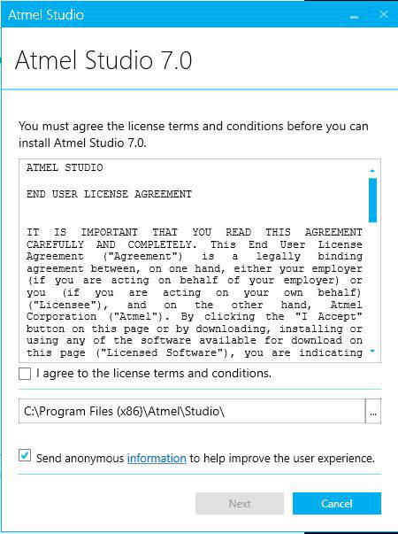
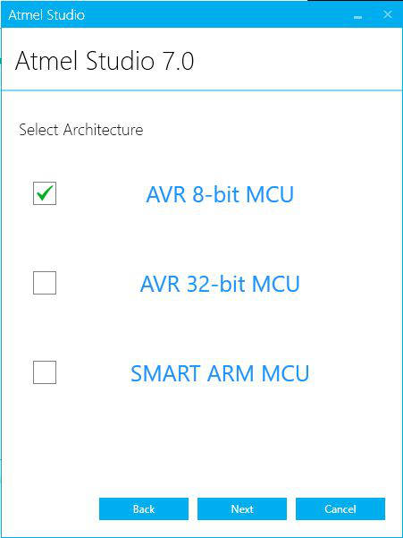
After downloading Atmel Studio install the Software. First you have to accept the license agreement. Next step is the choice of the hardware we want to develop for. I choose 8-Bit that handles all of the ATMEL microcontroller I will programming for.
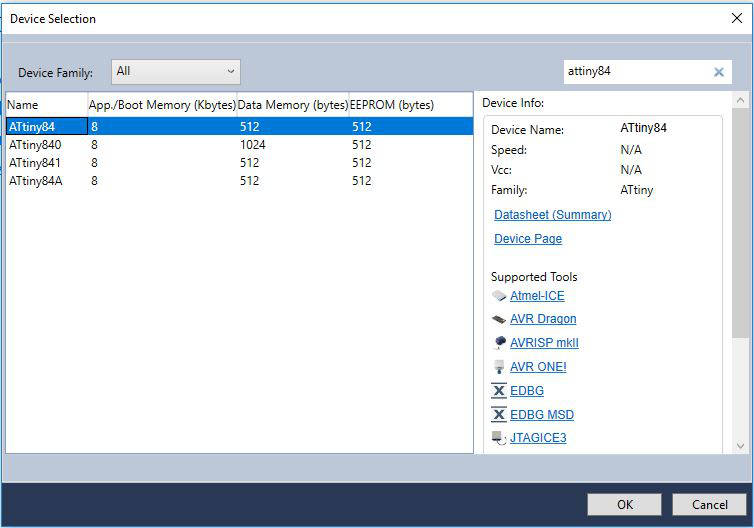
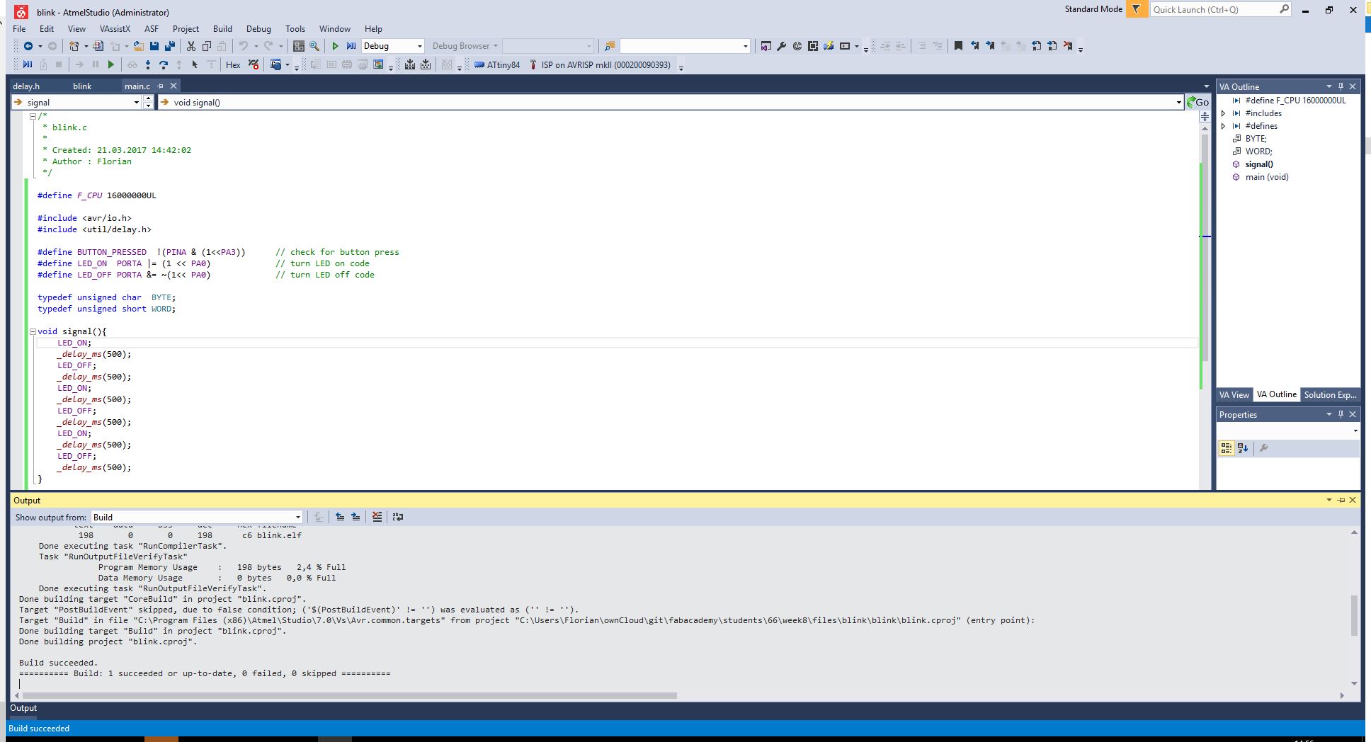
After the installation is complete I create a new project. Now I have to choose for wich microcontroller we will programming for. In this case it is the ATtiny84. When selecting the microcontroller you are also able to see the datasheet for that. When this is setup we have our IDE up and running. Now it's time to write some code. When a state is accomplished wen can select "Build Project". This is where the whole project is tried to compile. When there are any errors they are mentioned in the bottom debugging window. After fixing them we get the message that the project was compiled.
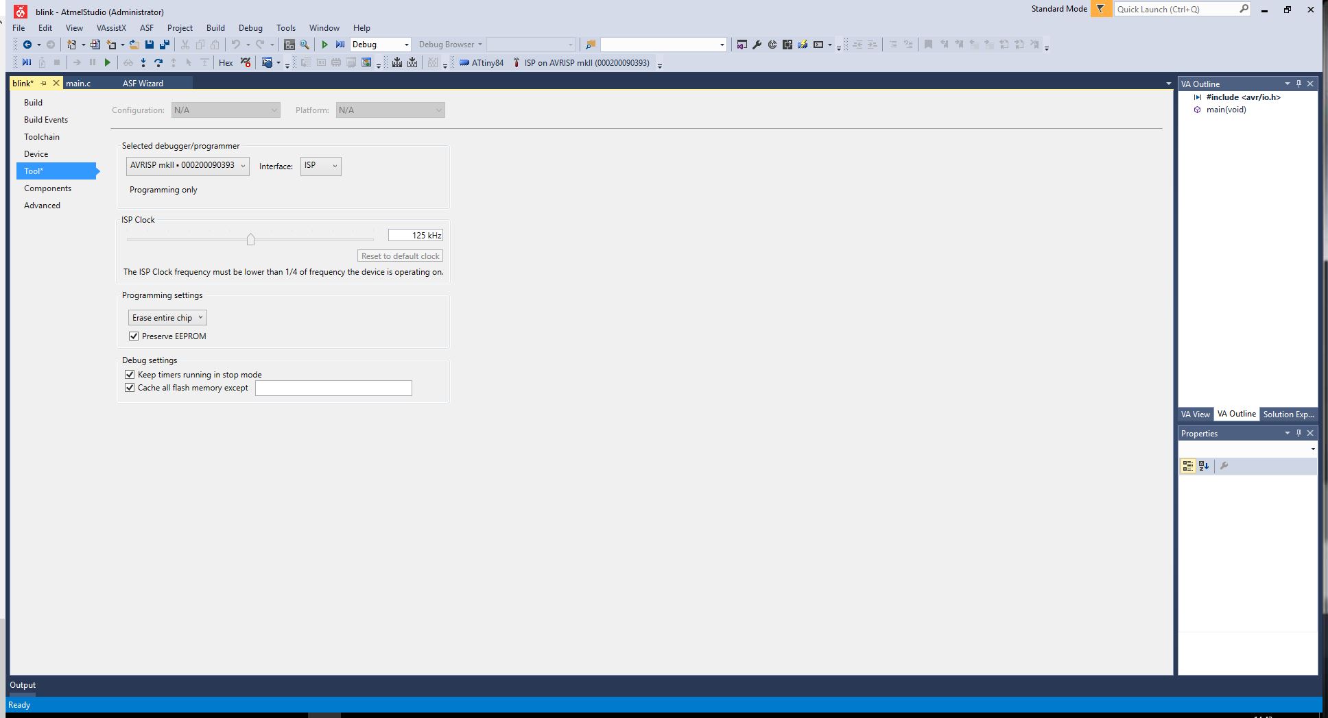
With the compiled project its time to flash the generated .hex file to the microcontroller. To do this you select the flash symbol on the upper toolbar. This opens a dialog that is managing the communication with the microcontroller. Here I select the programmer I used to communicate with the microcontroller.
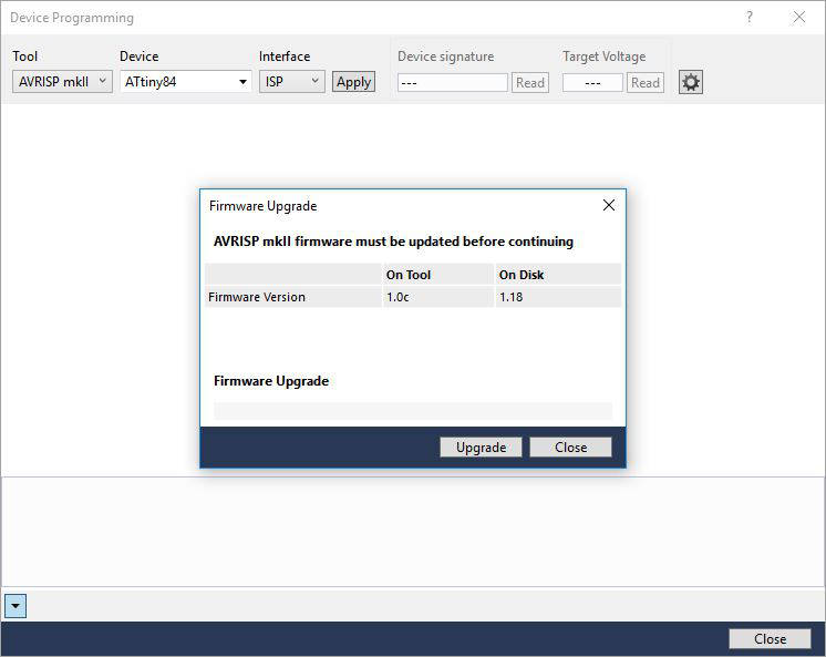
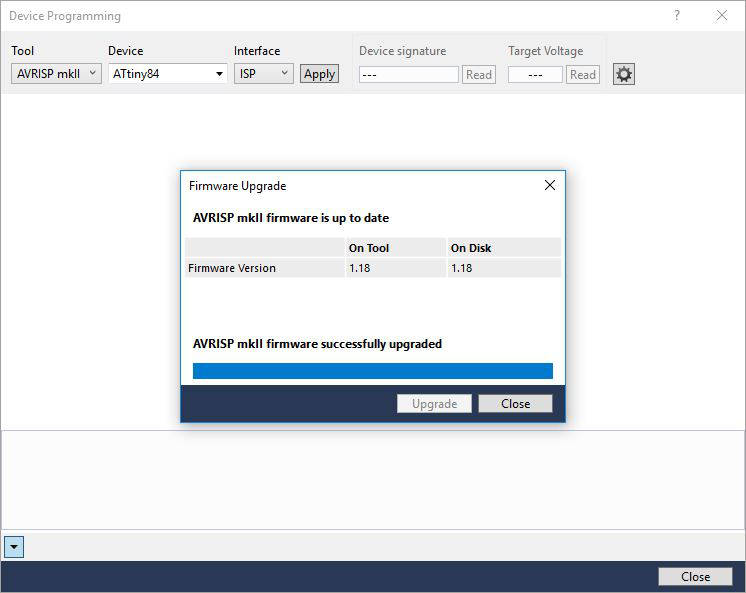
After selecting my connected ISP programmer the ATMEL mk2 ISP programmer the software detected that the firmware on the programmer was out of date. So it helped me to update the firmware on the programmer.
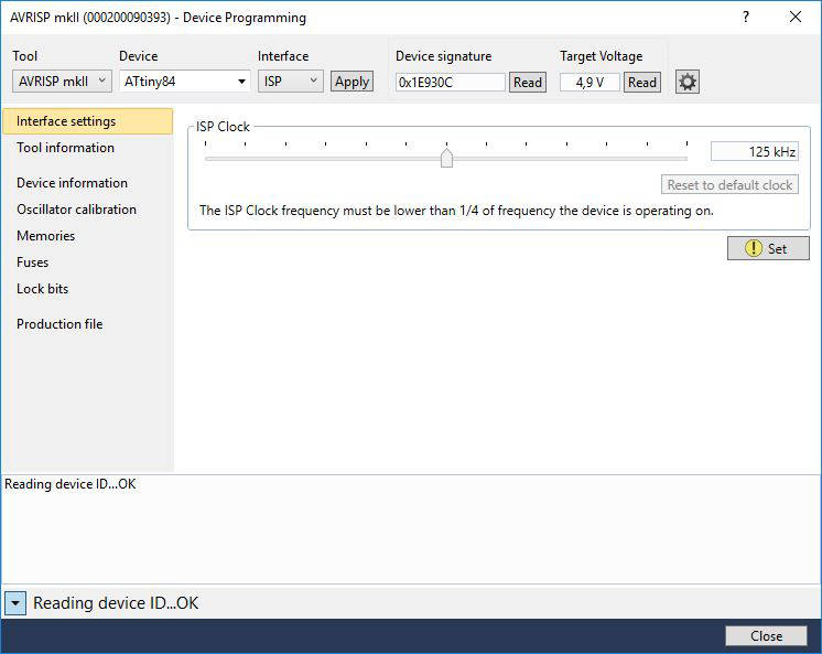
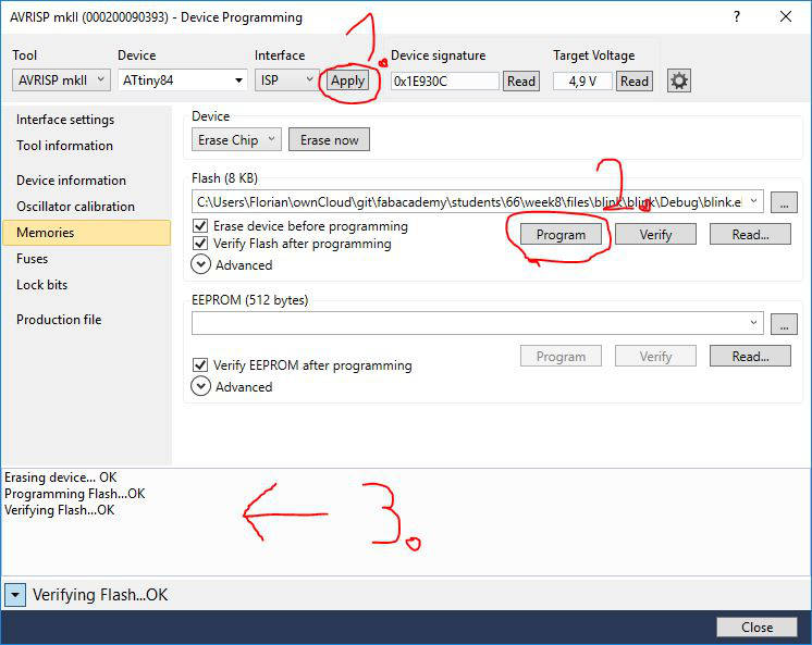
Now its with the updated programmer we can select apply at the top of the dialog. Atmel Studio will start testing the communication the the microcontoller. If this is successful the current voltage and device signature are read from the microcontroller and are given in the form fields.
Under the menu point fuses we can set the fuses as expected. When connecting a new chip we should configure the fuses on it. Here we can set options for the clock we are using and clock divider. Different microcontroller have different options here so consider your datasheet to setup the chip correctly and for your needs.
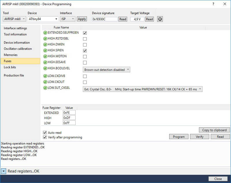
Whats left to do is to flash the compiled program to chip. This can be done under the menu point 'memories'. Here you can easily read and write the memory of the ATtiny84 and flash the program onto it.
Reading in the datasheet the know
The main and most difficult part this week was to study all the datasheet from the several chips I used and will be using. Browsing the internet and especially the Atmel homepage it where the datasheets can be found. Every bigger web shop that deals with the chips link to the Atmel site and their document base.
Important thing I learned here is that there are always the typed of datasheets. On the shop sites they link most of the time to the summary. The summary of a datasheet gives an overview about the specifications about the chip but when it comes to program them it is most likely that you will use the complete datasheet that is 5 times longer than the summary. Only on the complete datasheet you can find all the necessary information about the several register you will need to configure the chip and take advantage of its functionality.
During the week I studied several datasheets to see what I want to use in the next assignments. Because I was not happy with the ATtiny and the missing UART connection I looked also in the specs of the ATmega328.
UART communication talk with the microcontroller
Calculate the baud rate do the math
Next I want to take a look how to communicate with the microcontroller. Because I don't want to deal with software implementations of UART I had to change the microcontroller I use for this task. The ATtiny84 don't has an hardware implementation of UART. To prevent trouble with software libraries I never tested before I want to use a microcontroller that has a UART implementation in hardware. Because I will create a board the next weeks that has a bigger ATmega controller, I don't create another board design now.
I used another board of mine with a ATmega328 microcontroller that has a UART port in hardware. I used C in Atmel Studio to program the chip.
For UART communication I had to tell the microcontroller how fast it should communicate. This is a decision from speed to quality of the signal.

/*
* uart.c
* UART communication test ATmega2560
* Created: 21.03.2017 14:42:02
* Author : Florian
*/
#define F_CPU 16000000UL
#include <avr/io.h>
#include <util/delay.h>
#include <avr/interrupt.h>
#define BAUD 9600UL
#define UBRR0_Value ((F_CPU/(16*BAUD))-1)
#define LED_ON PORTB |= (1 << PB7) // turn LED on code
#define LED_OFF PORTB &= ~(1<< PB7) // turn LED off code
typedef unsigned char BYTE;
typedef unsigned short WORD;
int main (void) {
// Setting the Baudrate for transmission
UBRR0H = (UBRR0_Value >> 8);
UBRR0L = UBRR0_Value;
// Enable UART0 on the board pin 0->RX and 1->TX
UCSR0B = (1 << TXEN0) | (1 << RXEN0);
UCSR0C = (1 << UCSZ00) | (1 << UCSZ01);
// declare PA0 as output pin. This is where the motor and LED is connected
DDRB = (1 << PB7);
char sendChar = 'A';
// main loop
while (1) {
// TX
//UDR0 = sendChar;
//_delay_ms(1000);
sendChar += 1;
// RX
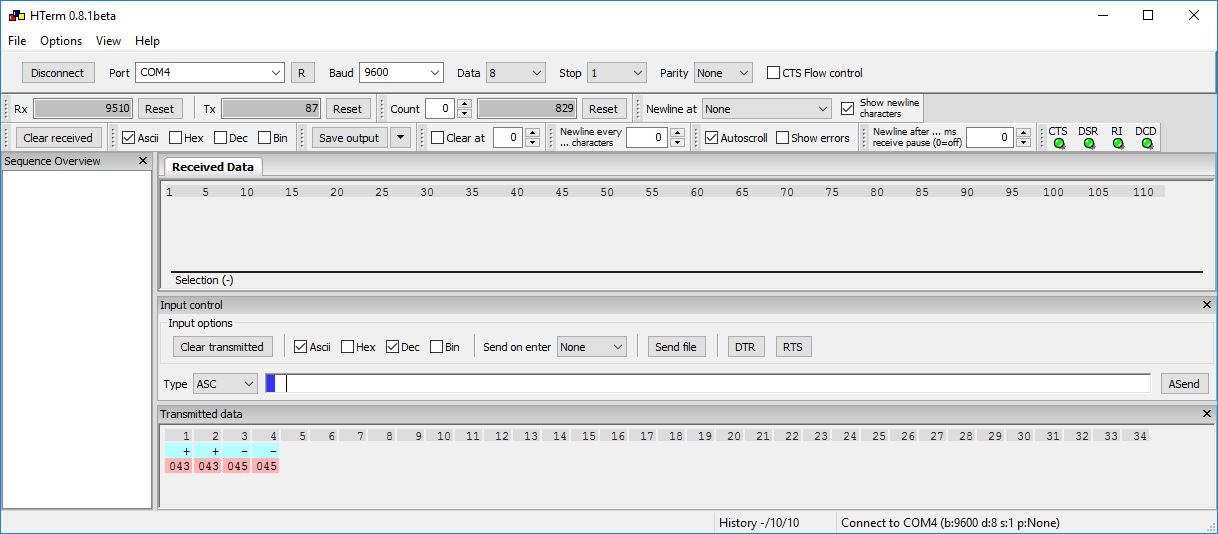
if (UDR0 == '+'){
LED_ON;
}else if(UDR0 == '-'){
LED_OFF;
}
}
return 1;
}
I ordered a cable on amazon to read the serial signal USB zu TTL cable.
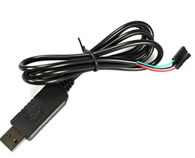
This cable uses the PL2303HX chip to convert from USB to TTL. Because this cable is only a cheap copy of a better one it was hard to find a driver for my windows 10 system.
The images below shows how I hooked up an ATMega board with my ISP programmer and my TTL cable. The pin header of the Mega made it easy to connect my TTL cable and test my C code for running a UART connection.
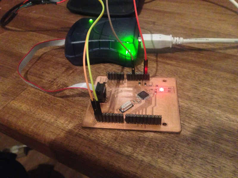

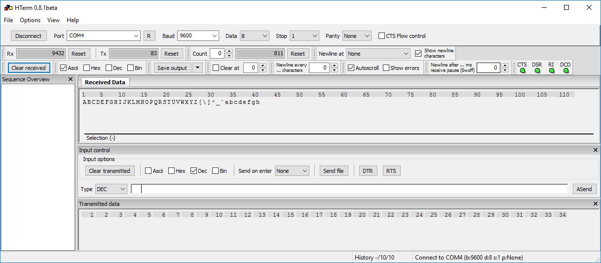
With this setup I was ready to test the serial communication. I searched for a gui to test the serial communication and come over the software hterm. It is an easy to unterstand straight forward way to connect to a UART connection. Starting the program and tell the software on which port the TTL cable is connected. Also set the baud rate
Download section the code I produced
| Simple led blink on button press with makefile for ATtiny84 | download |
| UART demo ATmega328 | download |