Electronics Design build an own circuit
I want to add multiple buttons for my circuit. To save some I/O pins on my ATtiny I used a simple R–2R resistor ladder network to connect all the buttons to one analog input.
Working with EAGLE design tool of my choice
I will continue using Eagle for my further projects. I like the UI of Eagle and when I search the internet and see hints on pages like Arduino, where you can download the Eagle schematics for each board, it seems to me that it is a well supported tool for hobbyists and semi professionals.
Also I like the fact that Eagle now comes from Autocad and this is the company my favorite CAD software comes from. I like that it is the same company and they already announced that in the future the tools will more integrate into each other. Also this is the software my mentor Tobias is using when I see him working with electronics thats why it feels like the right choice for my work in the FabAcademy.
Preparations and research dig into circuit
In research for this week it comes to my mind that the ATtiny84 I plan to use has a very limited amount of I/O. I try to find a way to maximize the amount of input devices and especially a way to connect more buttons. I learned the principal of a resistor network and connect them to an analog input pin of the controller. This way it is possible to connect several buttons to only one analog pin with an digital to analog (DAC) circuit.

For the design of the board I used the datasheet of my micro controller ATtiny84. You can find the datasheet in the atmel website ATtiny 24/44/84.

Because my instructor told me to use an easier design for this week I drop the idea of the resistor network for the multiple buttons and leave this idea for later. I also removed four of the motor connections and test it with one motor instead. After checking the schematics I also saw a mistake in this part of the schematic to I later had to update the motor control anyway.
Update design develop rev.2
After my first research and development of the first design I was requested to change this design and make it a little bit simpler for a first run. So I removed three of the four buttons and
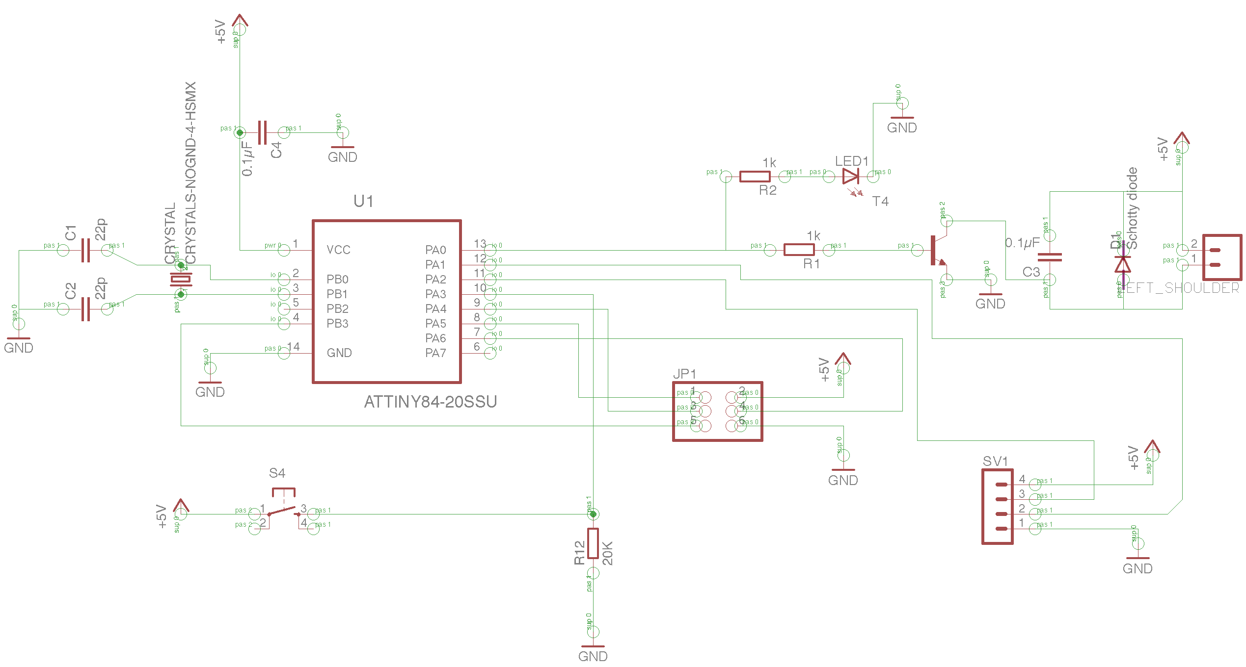
This was my updated design. I removed the button /resistor network and limit the board to only one button. I also removes three of the four transistor circuits to save parts and to test the mechanism.
Redesign part footprint update EAGLE library
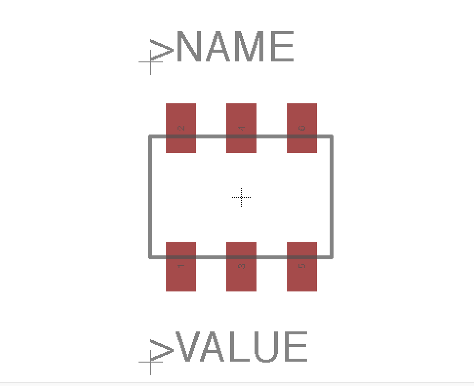
I get into trouble with the smd pinheader I ordered because the footprint is not matching the part because it was so big. Because I had a lot of these components I want to update my library so that future boards can benefit from the updated library.
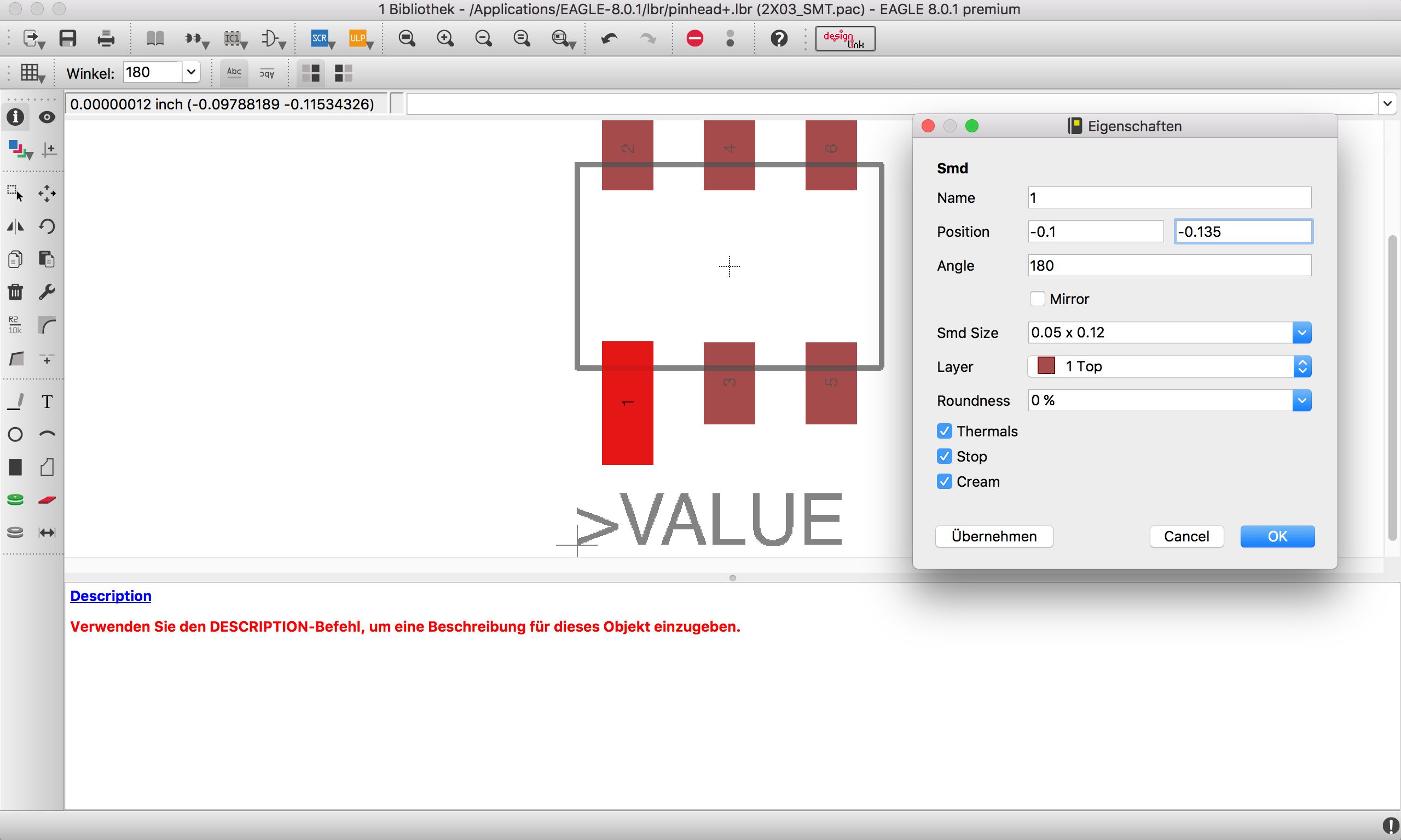
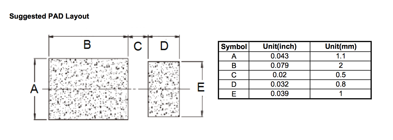
The schottky diode for example had an too big footprint. I had so shrink the pads to fit my ordered diodes. To find the matching size I read the datasheet of the diode from the vendor Diode datasheet.

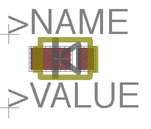
After editing the part in Eagle I saved the changes. To use the updated board design part of the part with the larger connectors I hat to update the libraries in my project so it updated the part in the project as well.
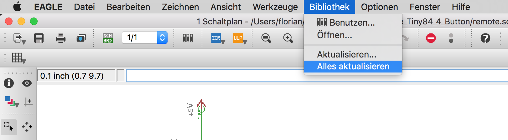

After the manipulation the footprint of the part I saved my changes. Because I used this part in my schematic, after opening my schematic of the board and updated my library with the top menu, EAGLE recognized that a part has changed and prompted me that my board layout has changed. I revisited my board layout and after milling another board the part now fits better and I will reuse the updated part in future projects.

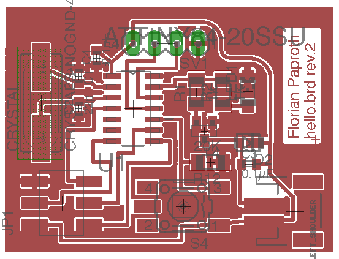
Next I rerouted the board to make it a little bit more space effective and that the board take benefit of the new part footprint.
Eagle DRCDesign Rule Check
Eagle has a nice tool to help you fix problems in your design before you send it the the mill and see after wasting material that you had design problems that the mill was not able to handle.
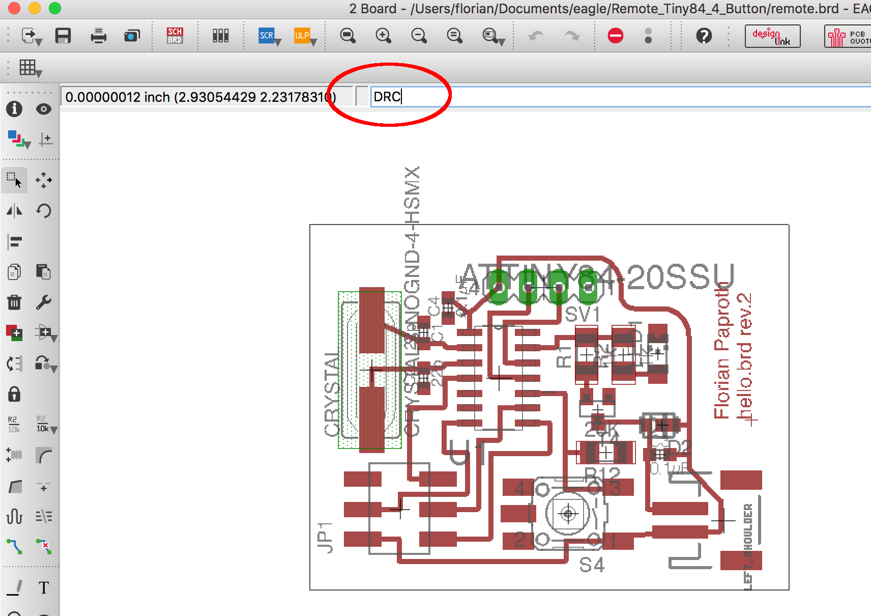
In eagle when you are in the board view you can type DRC into your command line and press enter. The result is that the DRC open window shows up.

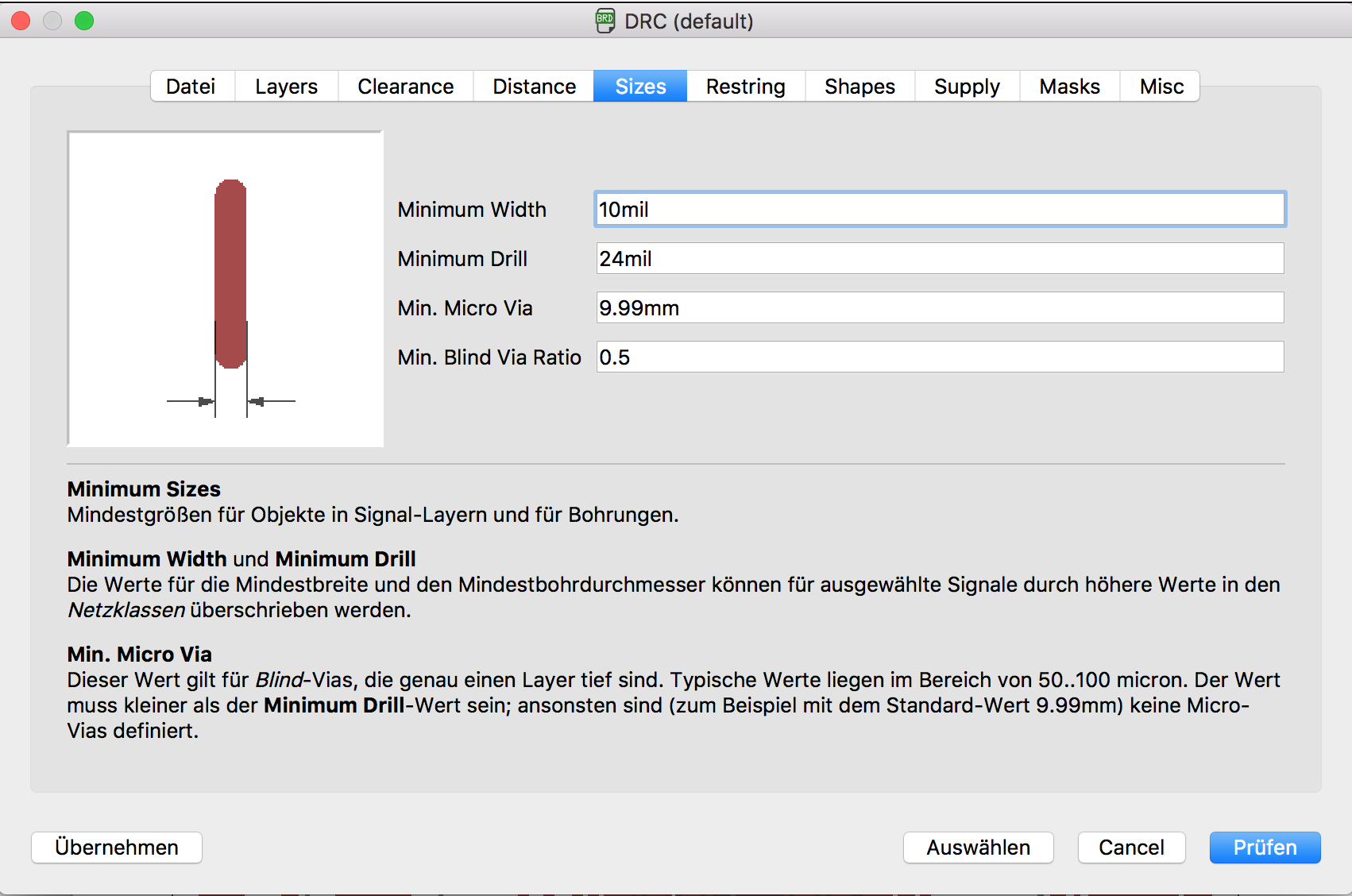
In the dialog you are able to import the design rules that maybe comes with your CNC machine. When it don't comes with one or you have made customizations you can set all the test parameter into the tabs in this dialog.
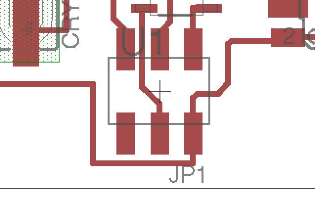
With our parameters set I hit enter and immediately see whats wrong with my design.
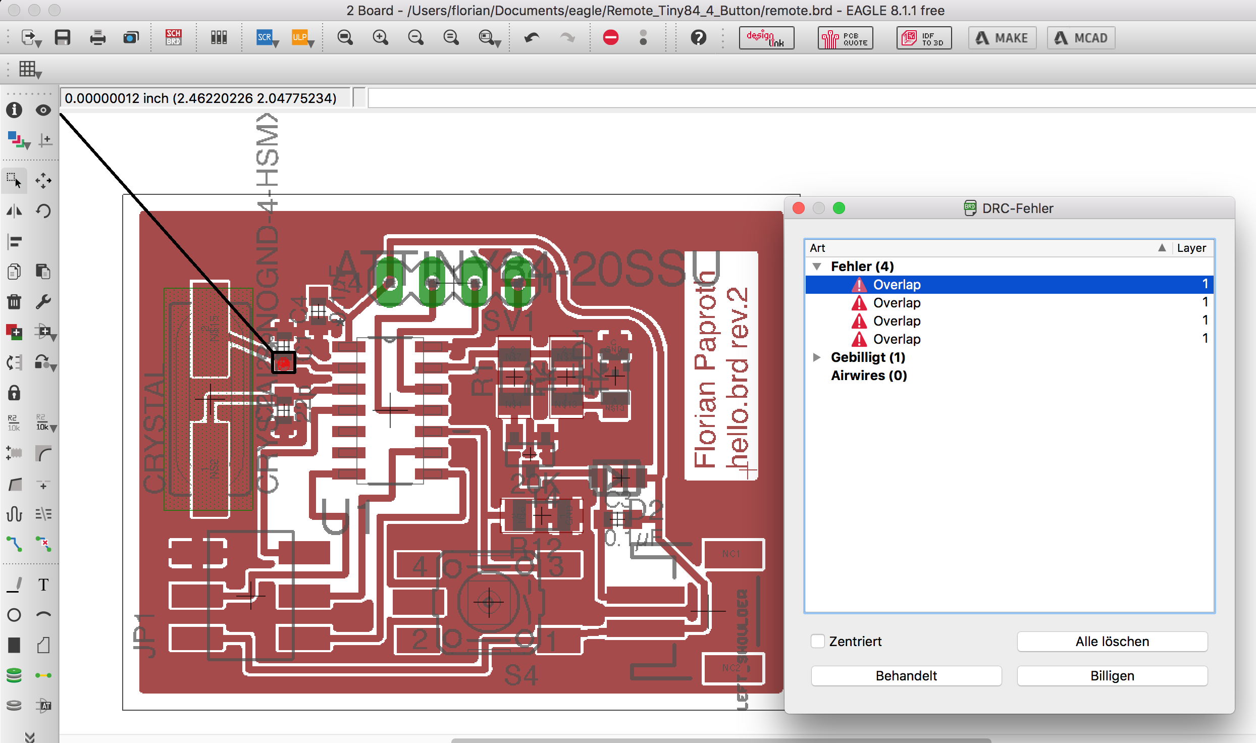
Here the design rules has detected that a pad of one of my parts is too close to a cut that the mill is eventually not able to handle. So I fixed the problem and check again.
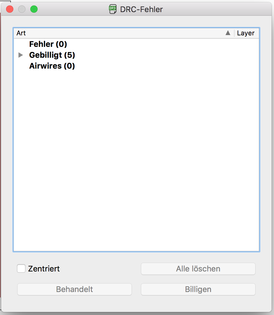
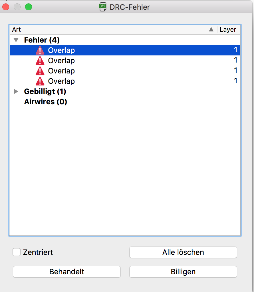
When all problems are solved or marked that you think they will not cause problems because you know something the DRC doesn't the list of problems become empty and you are ready to mill your PCB.
It's time to export the files from EAGLE to get the design into the Mill software.
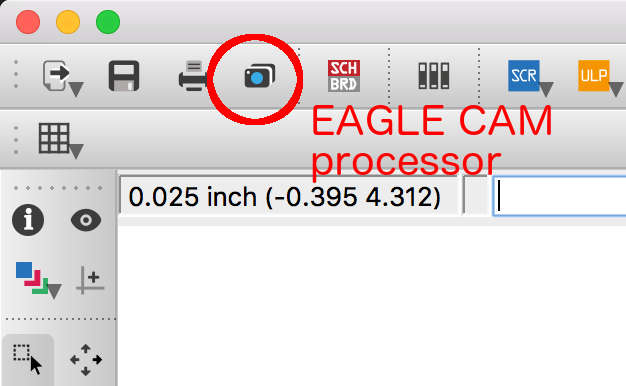
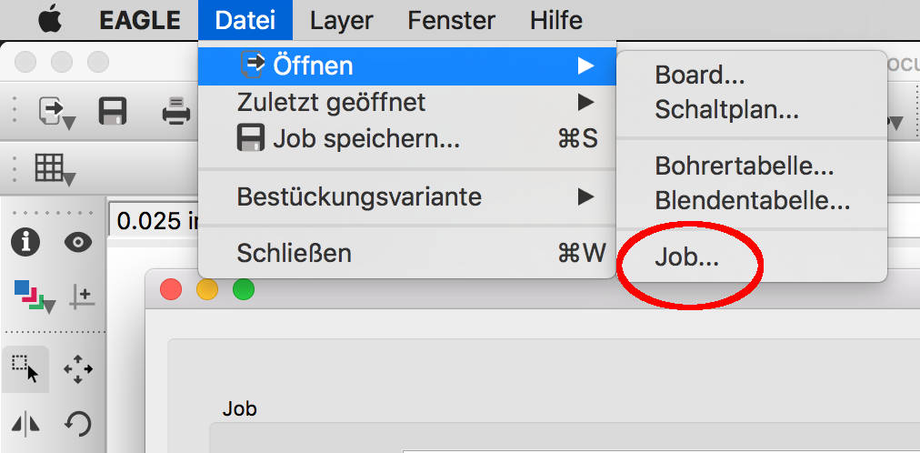
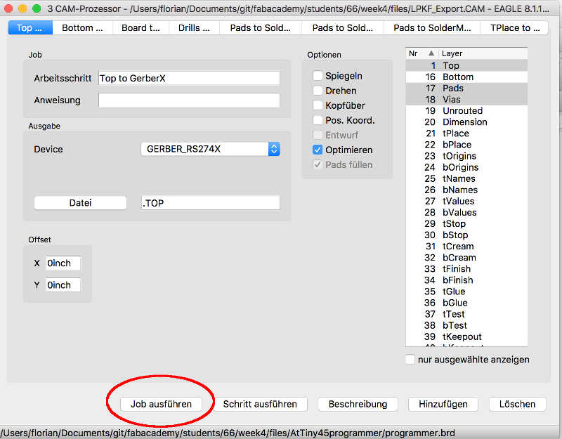
Here you can download the LPKF cam configuration also the ready to import files for the LPKF software. To do so you click in EAGLE in the CAM processor image in the top toolbar. The images above show the steps to take to export machine files from EAGLE. You have to load a Job. This is some kind of confusing but this means in general to load a configuration how to export files. In a .cam file are all the configurations what is the electronic mill capable off. You can get the .cam file for our LPKF machine in the download section below.
Download section
| LPKF cam export job for EAGLE export | download |
| ready to mill files (zip) | download |
Test the board is everything working
To test the board I created I flashed a small sample program to the chip because I want to check if it is working theoretically and for testing the soldering job. For this purpose I want to switch the state of the PA0 pin where the motor connector and the status LED is connected.
//main.c ATtiny84 Blink example

#include <avr/io.h>
#include <util/delay.h>

#define F_CPU 16000000

int main (void) {
  // declare PA0 as output pin. This is where the motor and LED is connected
  DDRA = (1 << PA0);

  // main loop
  while (1) {

    // set PA0 high
    PORTA = (1 << PA0);

    _delay_ms(100);

    // set PA0 low
    PORTA &= ~(1 << PA0);

    _delay_ms(600);
  }

  return 1;
}
After editing the makefile to fit it for my ATtiny84 and update the settings of the fuses I flashed the program onto the chip with the command make flash on the command line. Because I had everything set up on my Mac in the previous assignment like the arvdude the process was very straight forward.
When I saw the LED was blinking as expected I also updated the fuses on the chip to use the external crystal I used in my design. This was done by make fuse.
Feel free to use my design for your own project.
Download section rebuild the board
| EAGLE project archive with schematics and board design | download |
| Test code and makefile | download |
Bill of materials parts to rebuild the board by yourself
| Qty | Value | Device | Package | Parts | Description | |
| 1 | -NPN-SOT23-EBC | SOT23-EBC | T4 | NPN Transistror | ||
| 1 | CONN_02-JST-2MM-SMT | JST-2-SMD | LEFT_SHOULDER | Multi connection point. Often used as Generic Header-pin footprint for 0.1 inch spaced/style header connections | ||
| 1 | DIODE-DO214AC | DO214AC | D2 | DIODE | ||
| 1 | LEDCHIPLED_1206 | CHIPLED_1206 | LED1 | LED | ||
| 1 | LSG | SCHURTER_LSG | S4 | |||
| 1 | MA04-1 | MA04-1 | SV1 | PIN HEADER | ||
| 1 | PINHD-2X3SMT | 2X03_SMT | JP1 | PIN HEADER | ||
| 2 | 0.1µF | C-EUC0603K | C0603K | C3, C4 | CAPACITOR, European symbol | |
| 2 | 1k | R-EU_R1206 | R1206 | R1, R2 | RESISTOR, European symbol | |
| 1 | 20K | R-EU_R1206 | R1206 | R12 | RESISTOR, European symbol | |
| 2 | 22p | C-EUC0603K | C0603K | C1, C2 | CAPACITOR, European symbol | |
| 1 | ATTINY84-20SSU | ATTINY84-20SSU | SOIC127P600X175-14N | U1 | 8-bit Microcontroller with Bytes In-System Programmable Flash | |
| 1 | CRYSTALS-NOGND-4-HSMX | CRYSTALS-NOGND-4-HSMX | HC49-4-HSMX | CRYSTAL | CRYSTALS CAN NOT GROUNDED |