3D Scanning and Printing additive production
Discover our 3D printer what it can do and what not
Teamwork discover together
This task was a teamwork exercise so we created a documentation site together to describe the abilities of our 3D printer. Please follow the link below to see the group assignment and come back afterwards, if you want to.
Design and 3D print an object that could not be made subtractively more than CNC can do
Build the 3D model start from scratch
Outline what to do ok, 2D first to build better 3D
Starting into week 3 assignment I had to find an idea for my week project. I have to build something, that cannot be build with a subtracting method. So I thought that it would be an good idea to build something that consist of several parts that cannot be separated. The parts should only be put together during the build process. A bearing should do this job but not a normal bearing where the the balls are held together with a cage. I decide to create it with rolls that are running in a rim. Because it will be no planetary gear and the rolls are able to move freely inside the rim they had to be more rolls so that they cannot pushed aside to remove the inner ring.
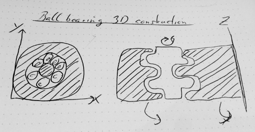
The drawing clarified how I want to build the bearing. At this point I can already see some issues in this design. I think when I realize the model as sketched before the problem will be that the rolls will roll in opposite directions at there border but it will fulfill the task of this week. So I decside to realize the concept as it is and test later how good the bearing will work.
Software I used my toolkit
Fusion 360
Fusion 360 is from Autodesk. It's similar with Inventor but it's cloud based. The best advantage that it has in comparison with Inventor is, that it can be installed on my Mac. So I can use it at my Windows workstation at home and on the go on my Macbook.
Cura
This is a slicer software from the makers of the Ultimaker 3D printer. Cura is also capable to work with other 3D printers.
Start CAD computer-aided-design
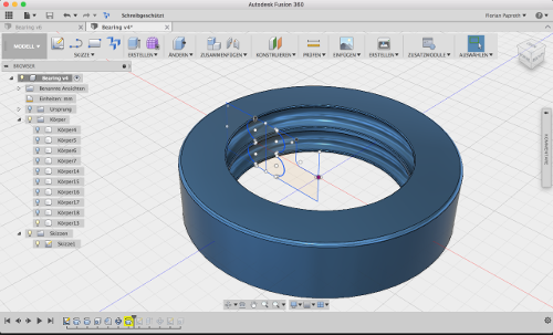
When starting the 3D model I had to think about how I will build it. I thought it is the easiest way to draw a profile of the bearing and extrude it later. This would be better as if I would extrude a circle first and have to subtract all the material beside the rolls.
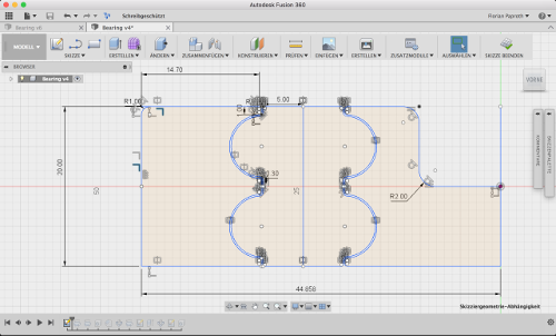
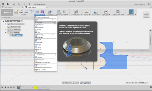
With the profile of the bearing I am able to extrude the 3 parts that the bearing consist of. As you can see in the image above a tool exist in Fusion that enable you to extrude shapes around a center axis. I can continue with the three shapes and extrude them. The outer and inner element will be extruded around the center axis and all the 360 degree. So I create the frame for the rolls. The roll itself is extrude around its own center axis so it will build the roll.

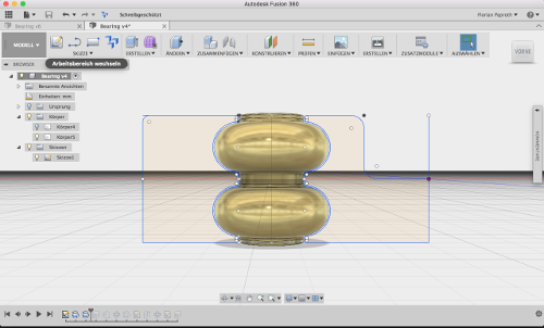
Every extrusion create a new body element. With the single roll I created I am able to clone it around the inner ring to have enough rolls to lock them inside the rim.
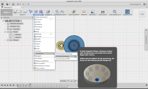

To multiply the roll I choose the polar arrangement tool. With the tool I select the item to clone. In my case I select the roll I created. The roll should be clones seven times and I selected the center axis of the model so the roll will be cloned on the path between the two rings I created before.
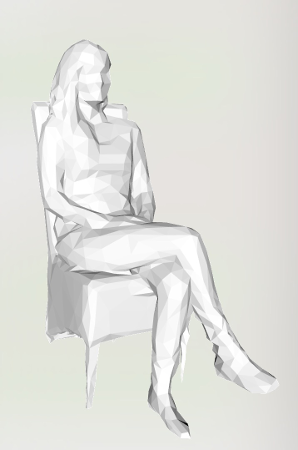
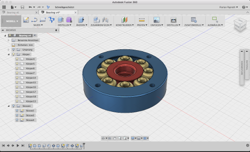
Finally render the finished model to have a sample image for showing the model on thingiverse or in this documentation.
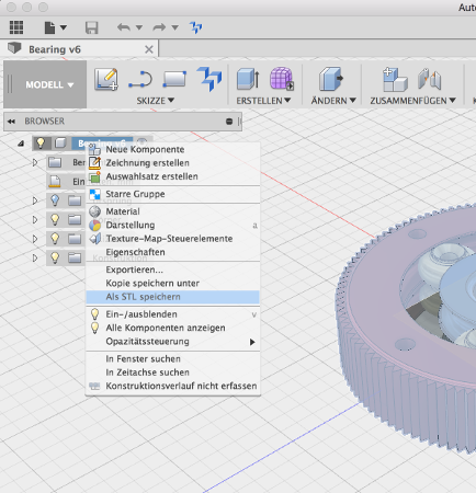
To work with the model in a slicer software like Curayou have to export it into a format that can be handled by the slicer. In this case I export the model as STL file.
Printing and go for a test-drive
Slicing cut model into layer
With the 3D model exported as an STL file, I was able to import it into Cura. In the configuration I let everything as suggested. I only switched to the low quality configuration. With this configuration selected the software calculated the estimated print time to about 4:30 so I will be able to see the result the same day. I only activate a brim so that the rolls don't come off the print platform during the print.

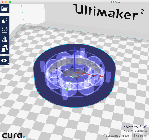
| Layer high | Infill | shell thickness | upper/bottom thickness | rim | cooling |
|---|---|---|---|---|---|
| 0.15mm | 10% | 1mm | 0.8mm | none | yes |
Cura generate the nessesary gcode for the 3D printer. I save the gcode file to a SD-card that I insert into our 3D printer. After that I started the print.
Production haha, its' alive
This is the model during the print process. Everything worked as expected.
I also uploaded a video of the bearing to show it under rotation speed.
Download section bearing yourself
| Bearing in Fusion 360 format | download |
| Bearing in step format | download |
| I also publish my design on thingiverse for everyone who want to print a bearing for himself. | link |
Scanned an object what the old Kinect sensor is capable of
In this part I wanted to figure out a cheap way for 3D scanning. In our FabLab we are normally using the iSense from iSense. The iSense is an iPad add-on that you can put on top of an iPad mini and using an iOS app to scan structures. The benefit is that it is easy to handle. The downside is that it cost round about 300€ at the moment and that it is limited by the graphic power and memory of the iPad. This result in a limit of scannable faces.
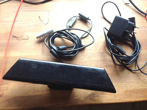
Thats why I want to go a different way and visit a local game-stop store that deals with used video game items. I had luck and was able to pick up an old xBox Kinect 360 sensor plus the needed adapters for connecting it to a PC or Mac for only 25€.

On Mac there are no additional driver needed to run the Kinect. For my windows 10 workstation I initially had to install Kinect for Windows SDK 1.8. It is necessary so install the version 1.8 of the SDK. There is also a newer Version available but this don't work with the first version the the Kinect sensor.


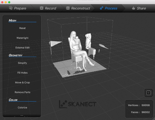
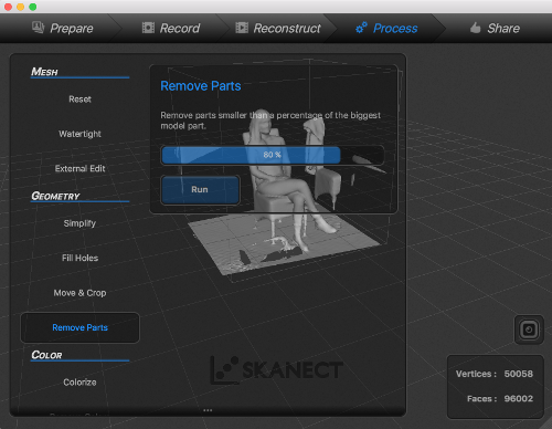
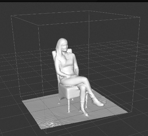
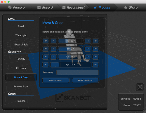

ToDo Document scanning process.