13. Input Devices
Assignments
- Measure something: add a sensor to a microcontroller board that you have designed and read it
Designing schematic & board layout
In this module, I decided to interface Ulatrasonic receiver and transmitter with the microcontroller as I am going to use the same sensor for my
final project. Whenever the transmitter will be pointed towards the receiver, the receiver will generate analog signal. This receiver is connected as input device to my microcontroller board.
Microcontroller will detect output signal generated my receiver and accordingly drive the motors.
I decided to use "40KHZ Ultrasonic Transducer Sensors".

Designing schematic & board for transmitter
For the transmitter (emitter), all we need is an oscillator set for a 35-45KHz frequency. There are many ways to achieve this - by using 555 timer or microcntroller PWM or dicrete components such as Transistors.
I decided to keep it simple and hence used transistors.
Here is the schematic for the ultrasonic transmitter.
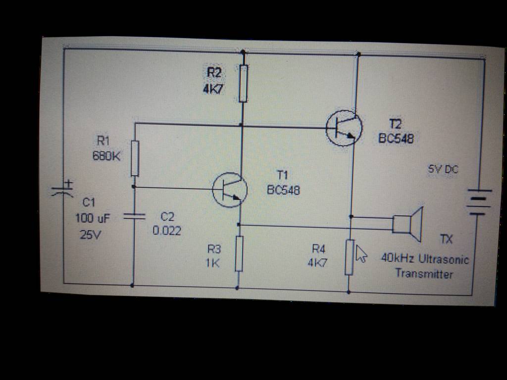
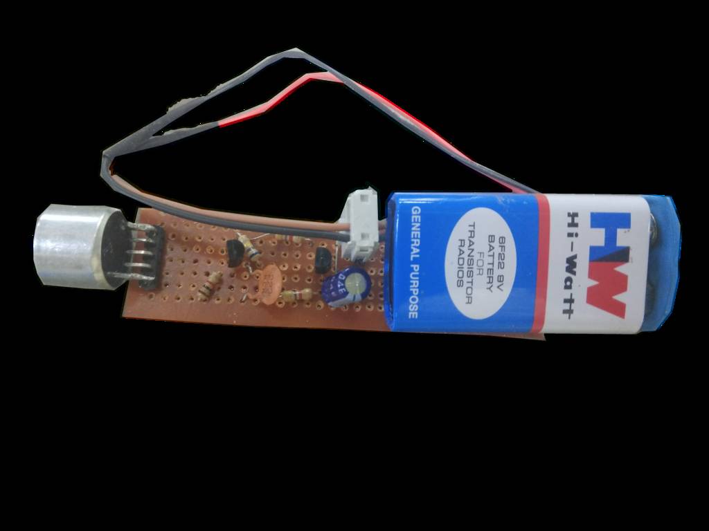
Also, this time I decided to try different method to make my transmitter and receiver circuits. I used general purpose PCB to make trasmitter circuit & I soldered the components and preprared the tracks by hand. Below is shown the transmitter PCB with 9V battery.
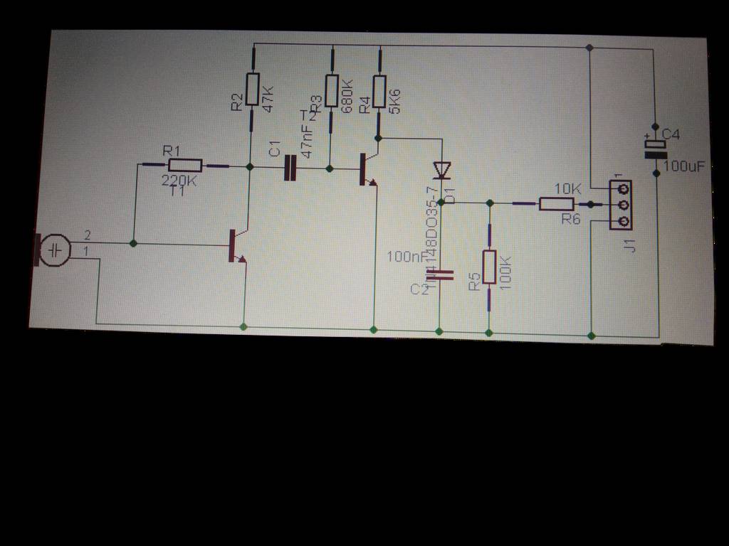
Designing schematic & board for receiver
The receiver is two amplifying transistors and a detector diode.
Here is the schematic for the ultrasonic transmitter.
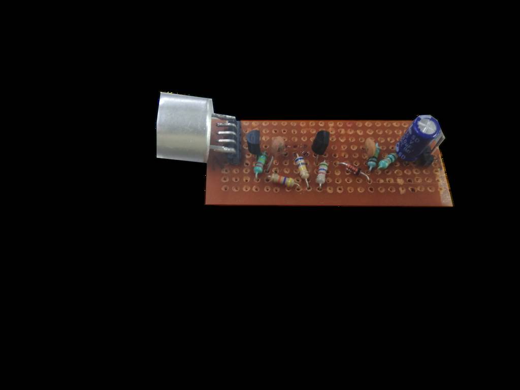
For receiver also, I used general purpose PCB to make the circuit & I soldered the components and preprared the tracks by hand. Below is shown the receiver PCB.
Testing the transmitter and receiver boards
Then I tested the two boards. Below is the video for the same. Whenever transmitter is pointed towards the receiver, we get max output (4V) at the receiver and as transmitter goes far from the receiver, the output voltage goes on decreasing.
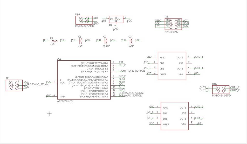
Designing schematic & board for main control board
I used attiny 44. I used two A4953 motor drivers for driving two geared dc motors. I connected output of ultrasonic receiver to ADC input of attiny 44.
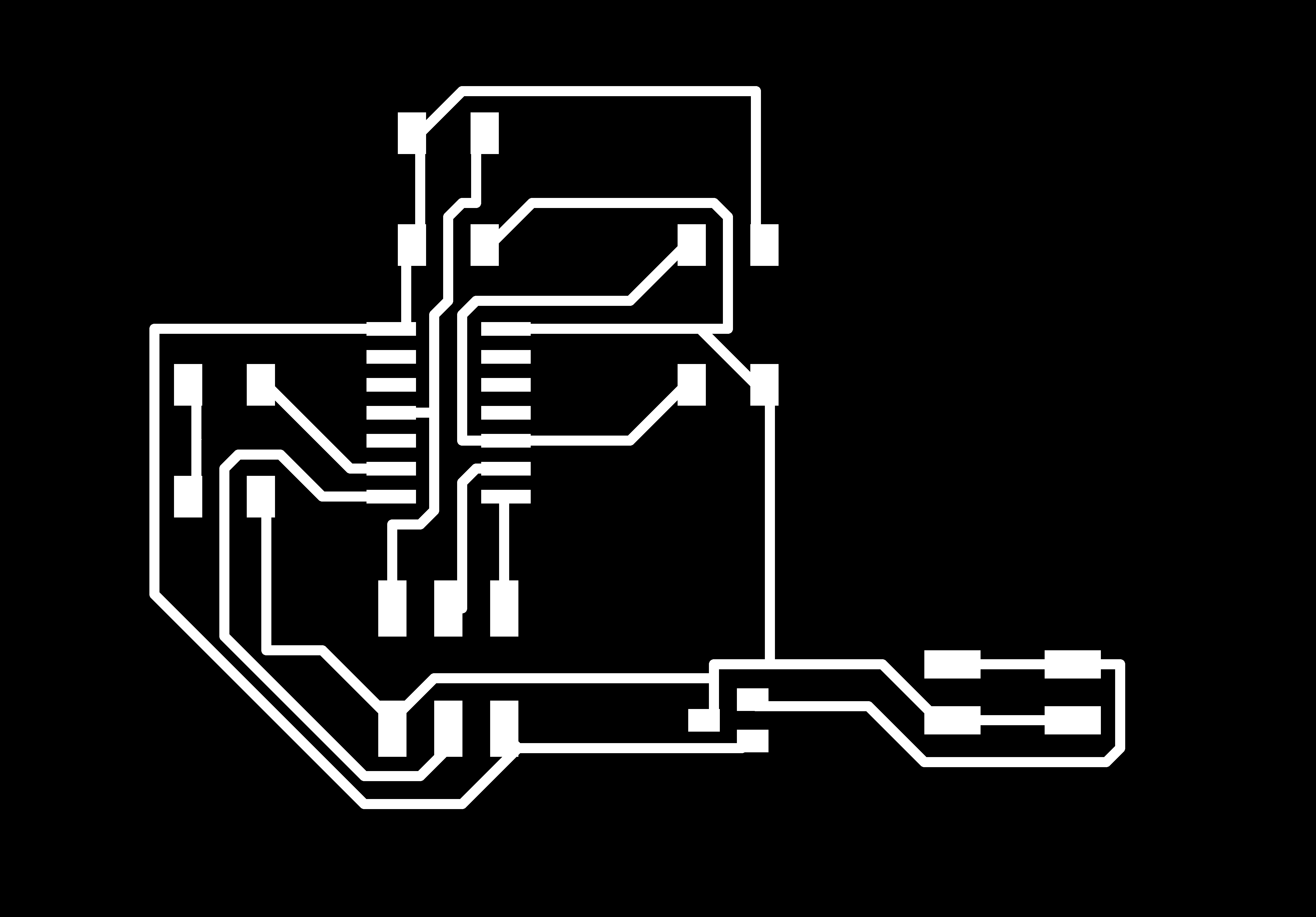
Below is shown the schematic & board layout of the same designed in eagle.

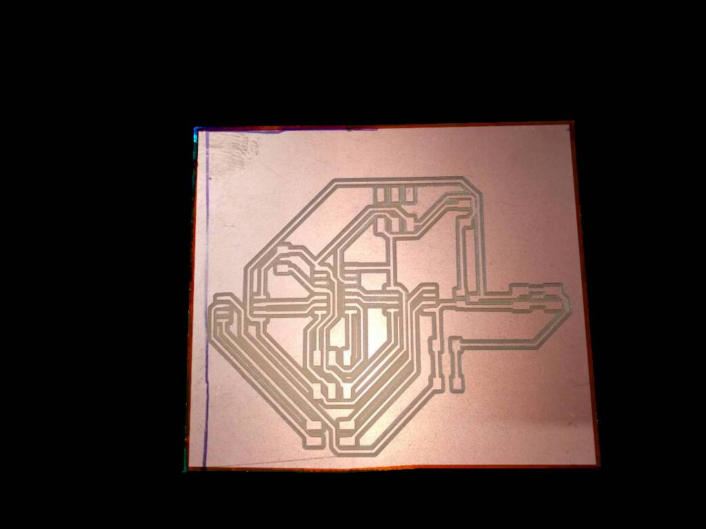
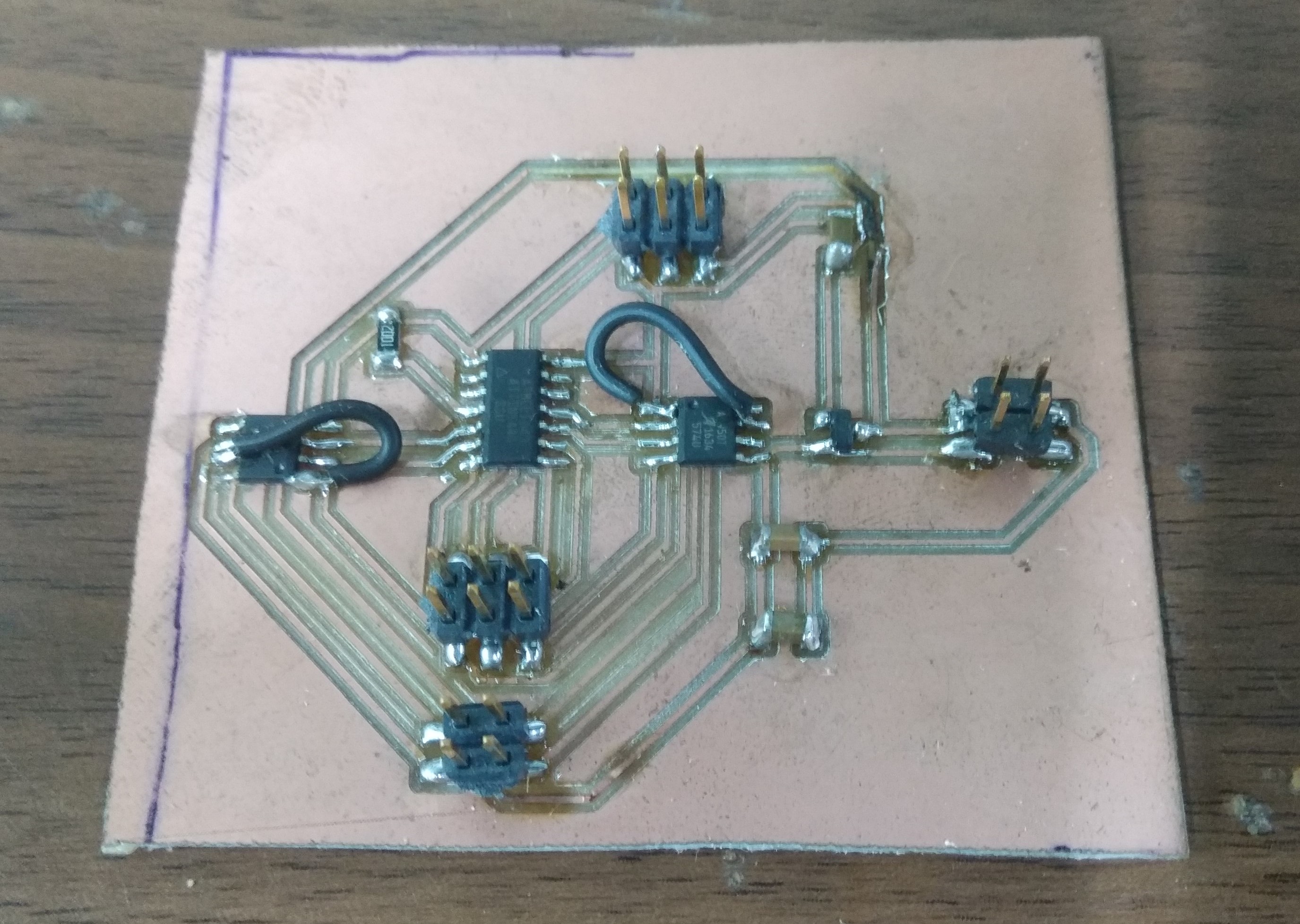
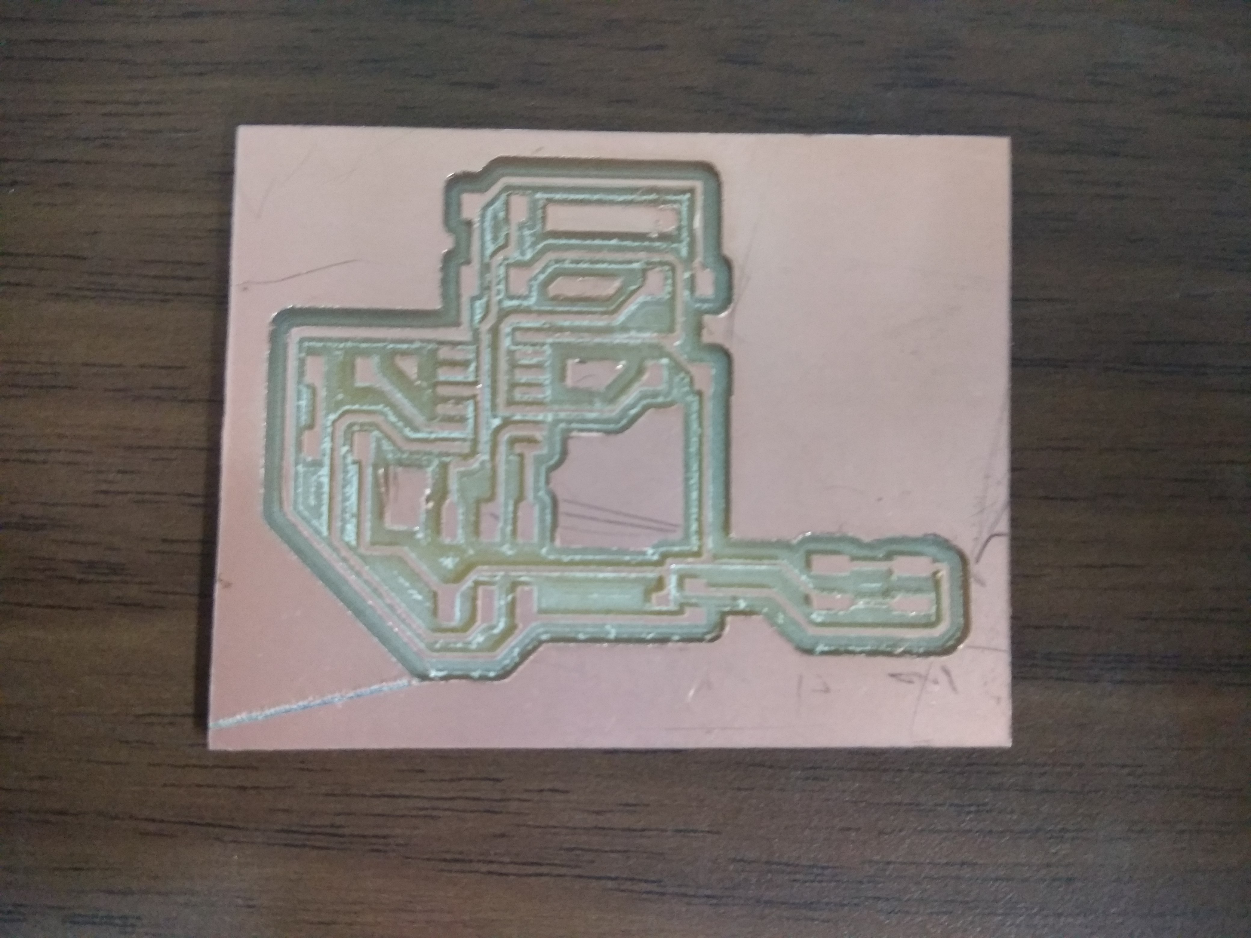
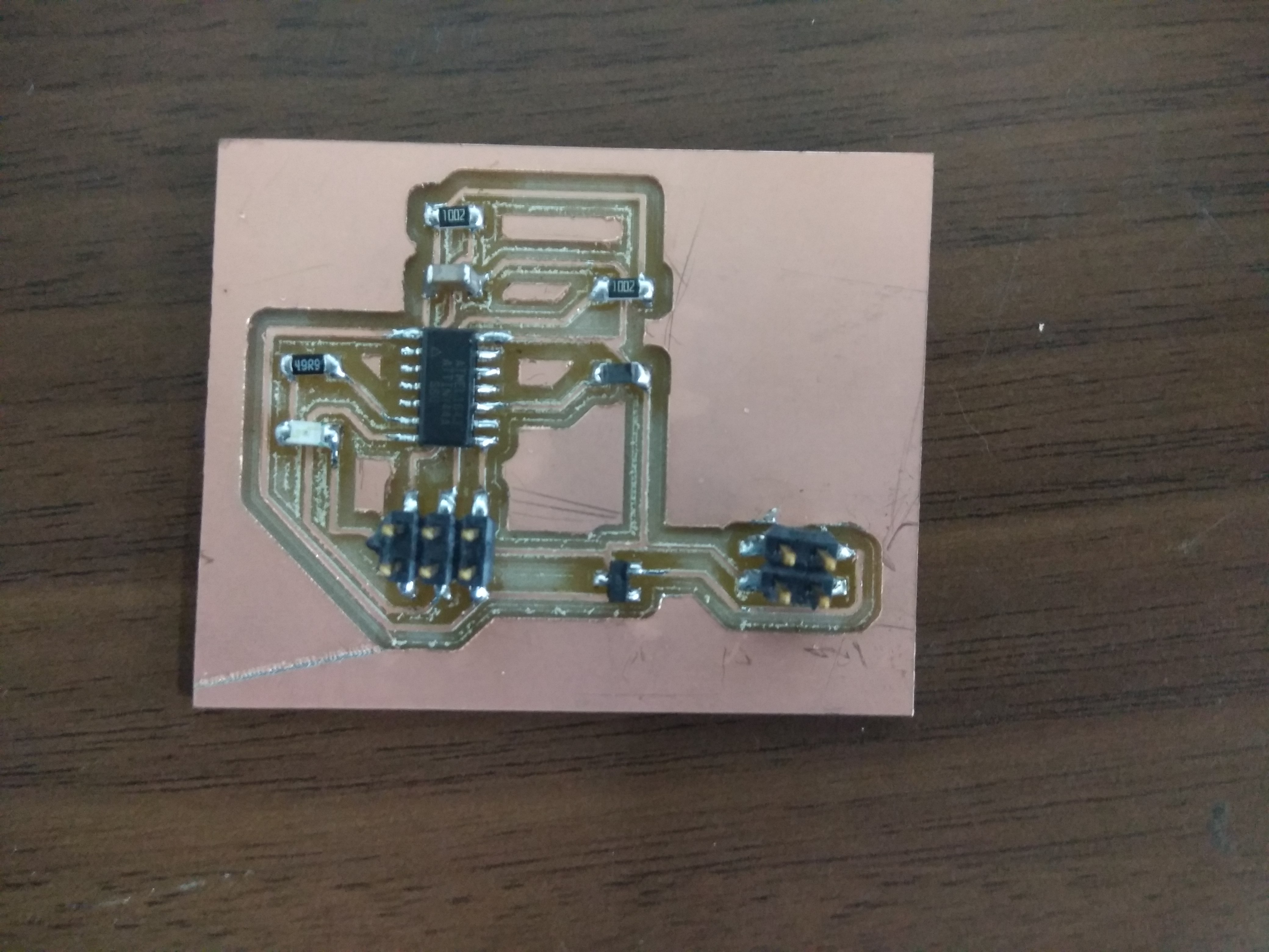
Here is the milled board & soldered board.
Embedded Programming
Here is the code.
/* * GccApplication3.c * * Created: 26-05-2017 21:06:13 * Author : cchaital */ #include# define F_CPU 1000000UL #include #include uint8_t ADCLow; // ADCL variable uint16_t ADCFull; // ADCL + ADCH variable #define set(port,pin) (port |= pin) // set port pin #define clear(port,pin) (port &= (~pin)) // clear port pin #define IN1_1 (1 << PA3) // IN1_1 #define IN2_1 (1 << PA2) // IN2_1 #define IN1_2 (1 << PB2) // IN1_2 #define IN2_2 (1 << PA7) // IN2_2 void motor_forward(); void motor_backward(); void motor_stop(); void motor_left_turn(); void motor_right_turn(); int main(void) { int i=0; ADMUX |= (0 << REFS0); // set the voltage reference ADMUX |= (0 << REFS1); // ADMUX |= (0 << ADLAR); // left adjust the result ADMUX |= (0 << MUX3) | (0 << MUX2) | (0 << MUX1) | (1 << MUX0); // select the ADC pin ADC1 PB2 ADCSRA |= (1 << ADEN); // Enable ADC ADCSRA |= (1 << ADPS2) | (1 << ADPS1) | (1 << ADPS0); // prescaler to 128 while (1) { ADCSRA |= (1 << ADSC); // Start the conversion while (ADCSRA & (1 << ADSC)); // Wait till the conversion is done ADCLow = ADCL; // get the ADCL 8 bits ADCFull = (ADCH<<8 | ADCLow); if((ADCFull>=300) && (ADCFull<=800)) { motor_forward(); i=0; } else if(ADCFull>=800) { motor_stop(); i=0; } else if(i<6) { motor_right_turn(); _delay_ms(100); motor_stop(); i++; } else { motor_left_turn(); _delay_ms(100); motor_stop(); } _delay_ms(1000); /*while(1) { motor_left_turn(); }*/ } } void motor_backward() { set(PORTA,IN1_1); set(PORTA,IN2_2); clear(PORTA,IN2_1); clear(PORTB,IN1_2); } void motor_forward() { clear(PORTA,IN1_1); clear(PORTA,IN2_2); set(PORTA,IN2_1); set(PORTB,IN1_2); } void motor_stop() { clear(PORTA,IN1_1); clear(PORTB,IN1_2); clear(PORTA,IN2_1); clear(PORTA,IN2_2); } void motor_left_turn() { set(PORTA,IN2_1); set(PORTA,IN2_2); clear(PORTA,IN1_1); clear(PORTB,IN1_2); } void motor_right_turn() { clear(PORTA,IN2_1); clear(PORTA,IN2_2); set(PORTA,IN1_1); set(PORTB,IN1_2); }
Output Video
Here are the output videos with different codes (delay between two ADC measurements was varied) ...
You can download files here...
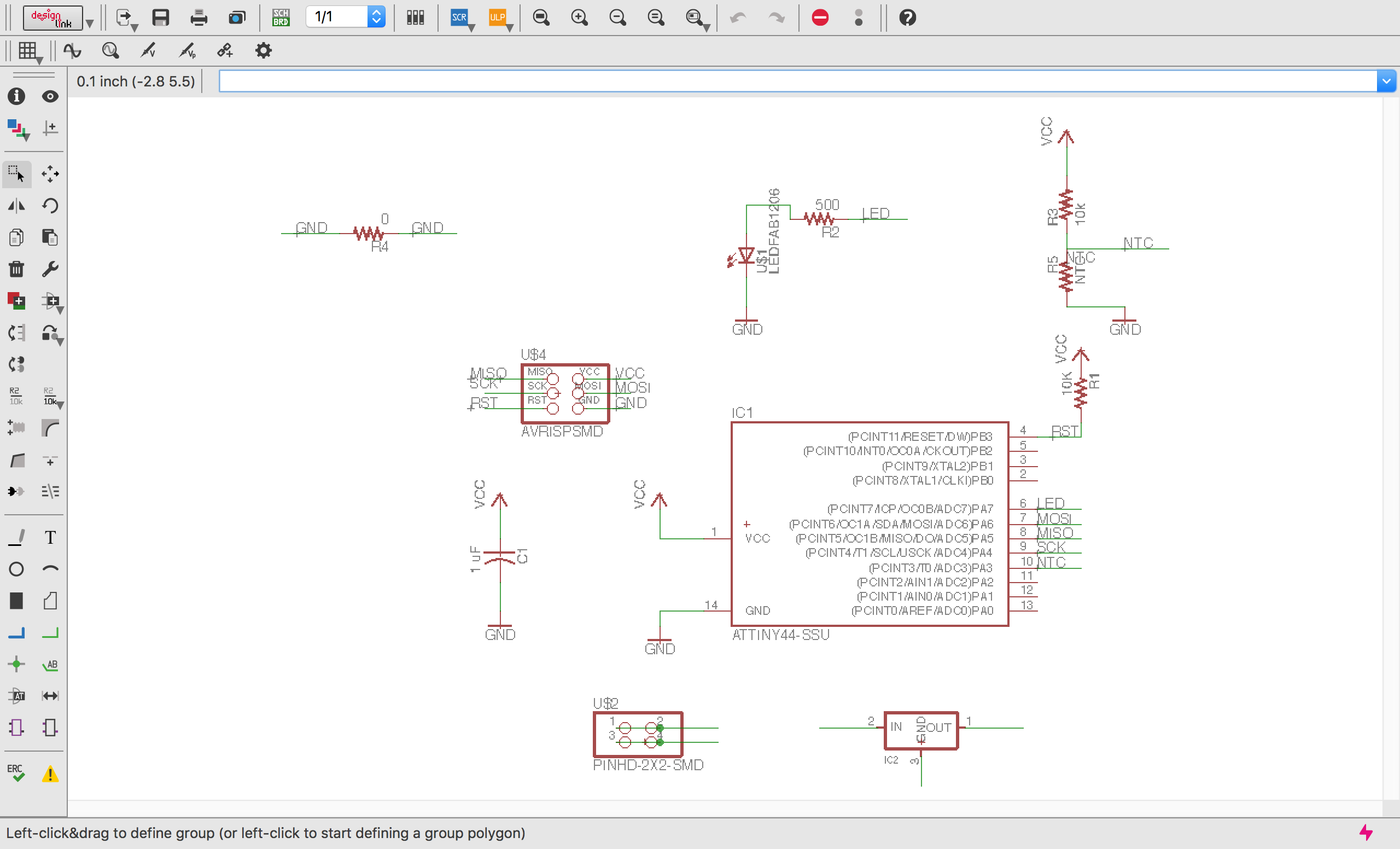
As per the comments from my global evaluator, it is necessary to make separate board for INPUT devices Week. So, I decided to make a board having NTC thermistor as input. When thermistor senses temp above 50degree, LED will glow otherwise LED will be off.
Designing schematic & board layout
First, I prepared schematic in eagle. (I used Attiny44.)
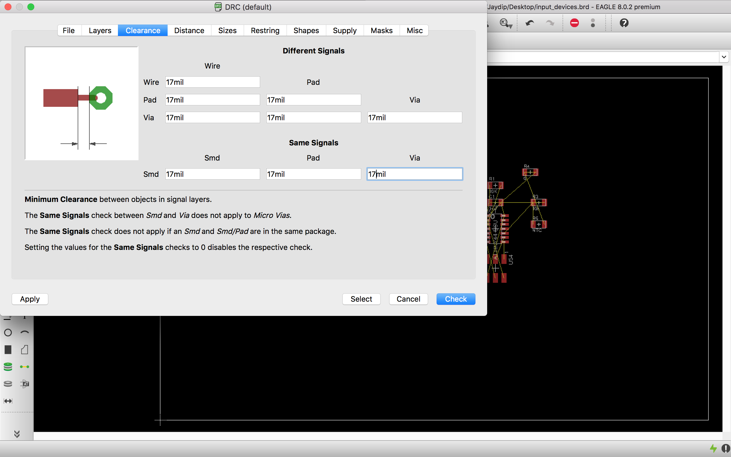
Next,I set track width & clearance under DRC rules.
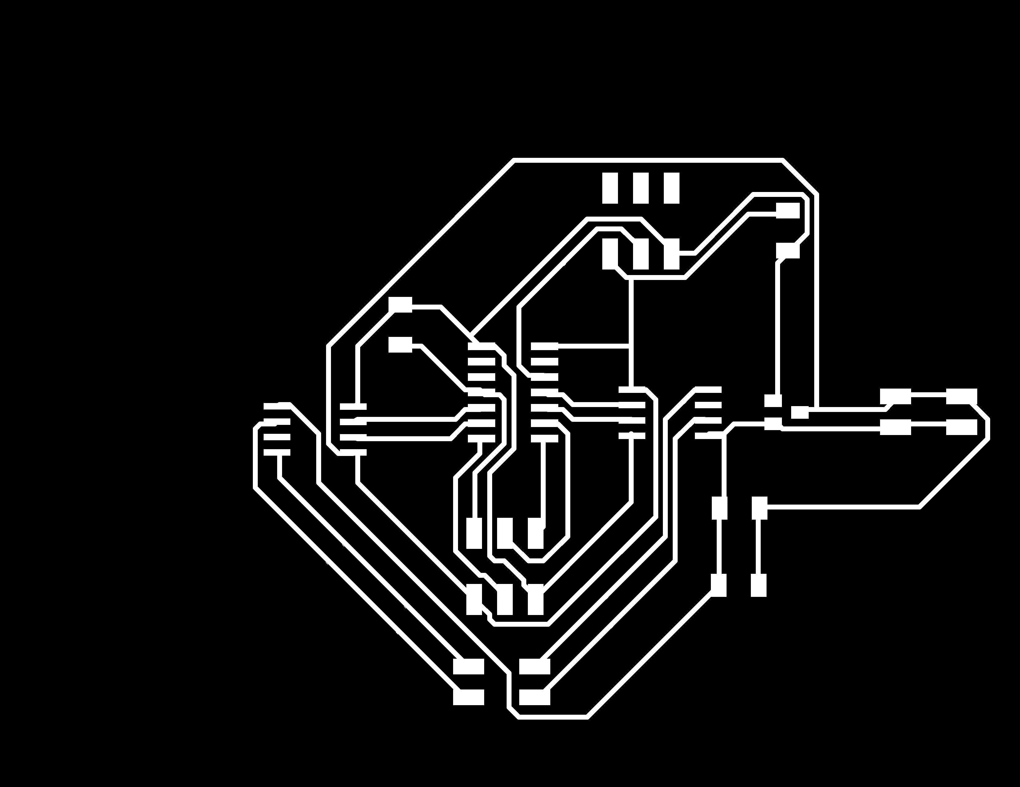
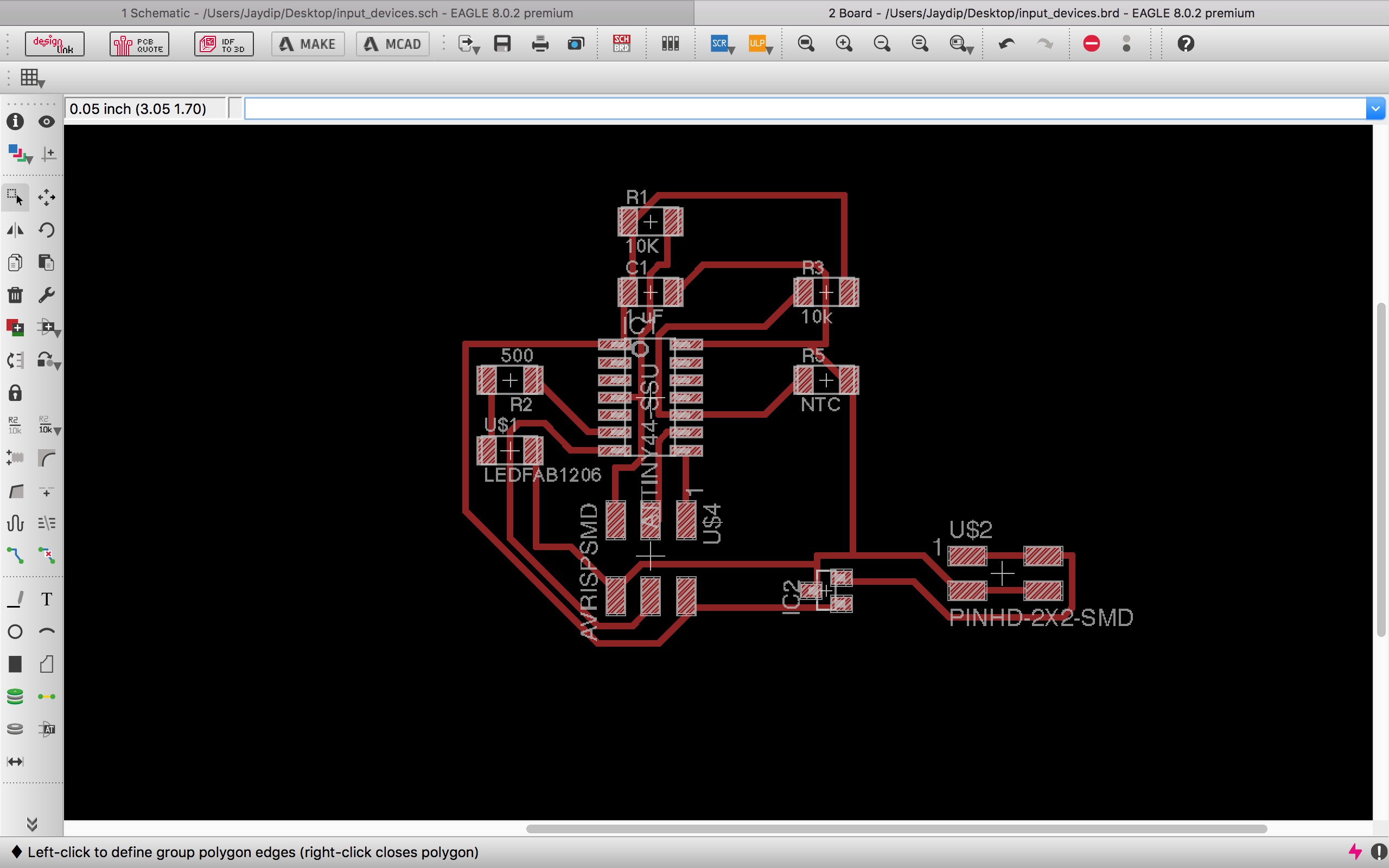
Then I prepared the PCB layout
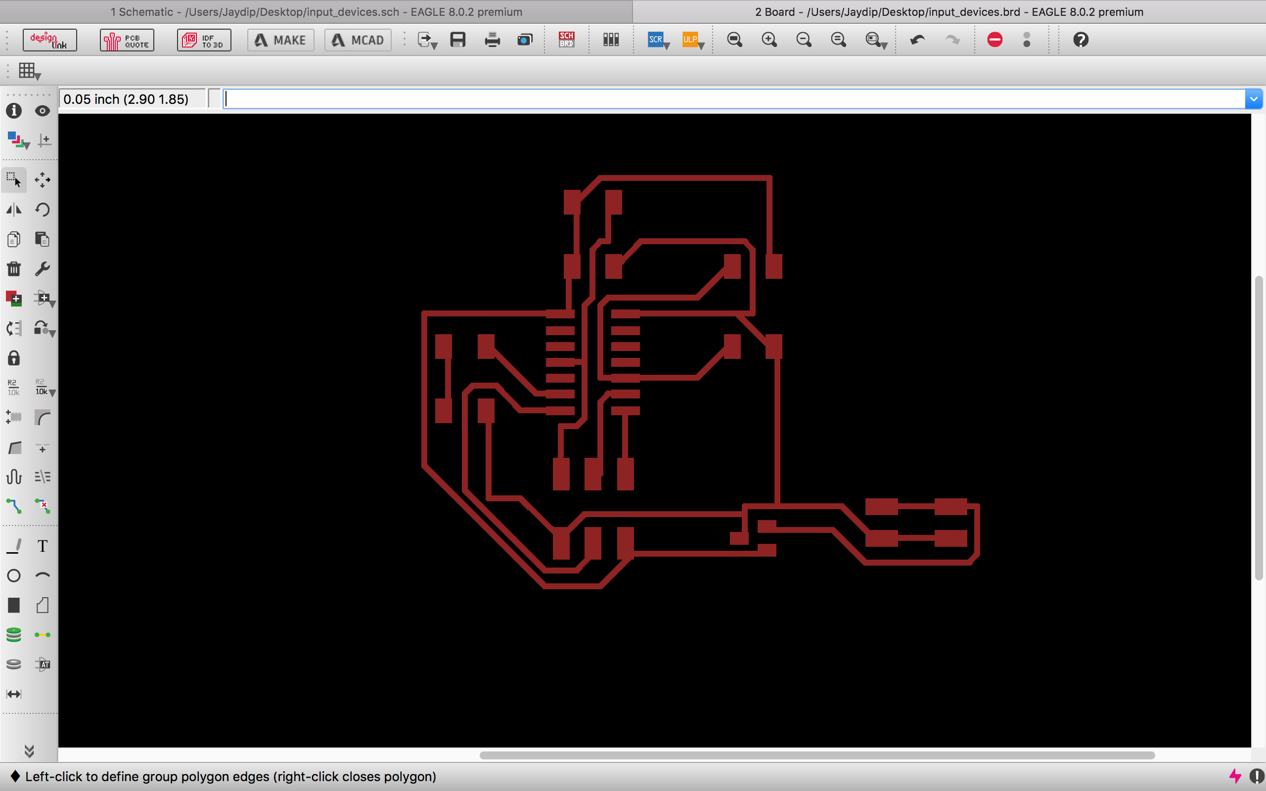
Then, I exported its monochrome png image.
Milling the PCB & soldering the components on the board
Next, I milled the PCB on Modella MDX-40.
Then,I soldered the components on PCB.
Embedded Programming
Here is the code.
/* * input_devices_ntc.c * * Created: 11-11-2017 16:46:30 * Author : cchaital */ #include# define F_CPU 1000000UL #include #include #include uint8_t ADCLow; // ADCL variable uint16_t ADCFull; // ADCL + ADCH variable int main(void) { DDRA =0b10000000; ADMUX |= (0 << REFS0); // set the voltage reference ADMUX |= (0 << REFS1); // ADMUX |= (0 << ADLAR); // left adjust the result ADMUX |= (0 << MUX3) | (0 << MUX2) | (1 << MUX1) | (1 << MUX0); // select the ADC pin ADC3 ADCSRA |= (1 << ADEN); // Enable ADC ADCSRA |= (1 << ADPS2) | (1 << ADPS1) | (1 << ADPS0); // prescaler to 128 while(1) { ADCSRA |= (1 << ADSC); // Start the conversion while (ADCSRA & (1 << ADSC)); // Wait till the conversion is done ADCLow = ADCL; // get the ADCL 8 bits ADCFull = (ADCH<<8 | ADCLow); if(ADCFull>450) { PORTA &= ~(1<<7);// Set PA7 low (Make LED OFF) } else { PORTA |= (1<<7);// Set PA7 high (Make LED ON) } } }
Output Video
Here are the output video... (I used blower to increase the temp of NTC above 50degree)