_Week13_INPUT DEVICES
_Introduction
On this week, like the weeks before working with electronics, We went through the same process of fabricate a board but this time adding a sensor (new for us) to a microcontroller for reading information about things in the environment (light, sound, movement, etc) and can give us measurements on this (or these).This time the heavy work will be the programming (maybe using another programming language than Arduino) and establish the correct communication between the programming, the microcontroller and the sensor to take the correct measurements.
_Background
With the easy logic to receive and send information, the input devices work directly related to the output devices so that they perform some specific function by digitizing the information obtained from environmental stimuli, providing data and control signals to an information processing system such As a computer or information appliance. The varied use nowdays of the sensors for the obtaining of big data of environment and of the cities and their inhabitants is a very important subject that is being approached by different companies to create strategies of products, sales and the way in which this one is provided this information.
Useful links:
_Week Assignments
_Workflow /Step by Step
_Choose a sensor.
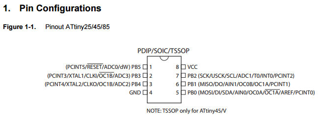
For this assignment I chose the phototransistor sensor working this time with the ATtiny 45 microcontroller (that is from the same configuration of the ATTiny 85 just having less memory), then firstly I saw the technical aspects of the phototransistor we have in the fablab to understand its operation and to see what communication with the microcontroller would be like.
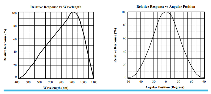
In short, this little guy can read a lighting spectrum inside the human vision and beyond like infrared light measured in Newton meter (nm) that is the unit for counting the wavelenght of the light. 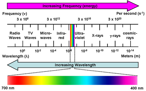
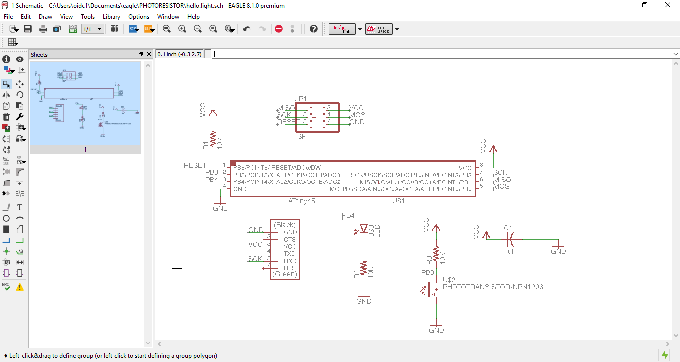
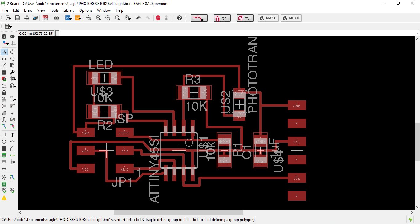
_Design board.
Next step designing the board in Eagle, once understood the pin out and how to connect every component and adding an LED that visually displays the response, this is the list of components:
And here is the pin out of the ATtiny 45 in the board:
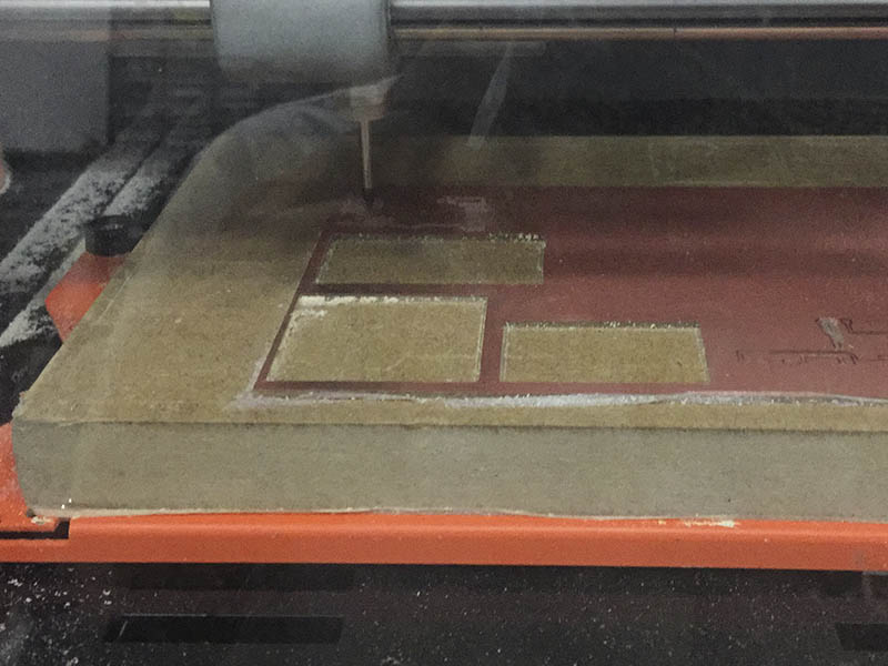
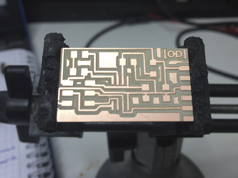
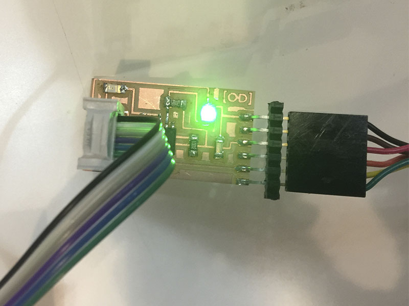
_Milling and soldering.
Following the same process for milling in the Monofab for having ready the board for soldering.
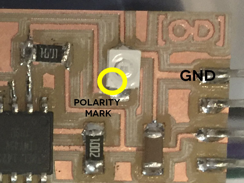
Afterwards, I solder all the components but looking in the datasheet of the phototransistor it have an special way to solder it as it goes in the picture.
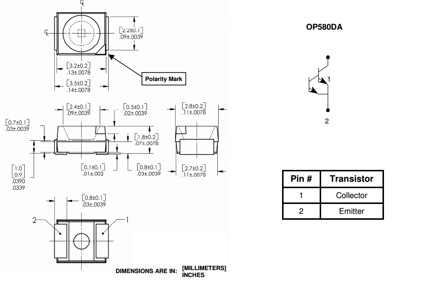 So the emitter have to be soldered to the GND (very carefully) paying attention of the polarity mark in the collector.
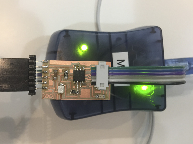
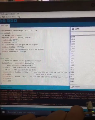
_Programming and measure.
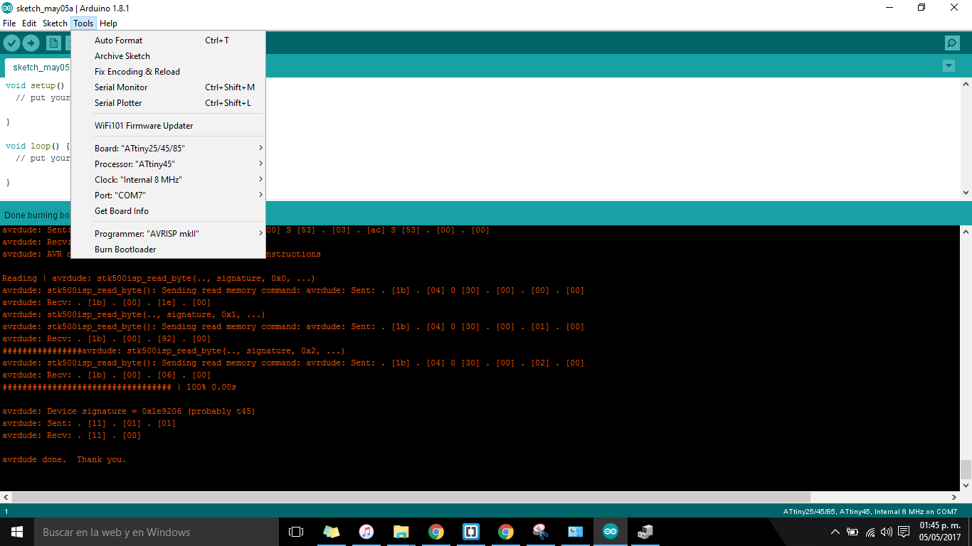
Now that the board its soldered, I program it in the Arduino IDE following the next steps:
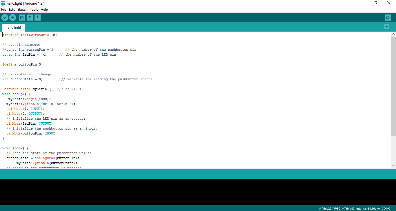
#include "SoftwareSerial.h"

// set pin numbers:
//const int buttonPin = 3;     // the number of the pushbutton pin
const int ledPin =  4;      // the number of the LED pin

#define buttonPin 3

// variables will change:
int buttonState = 0;         // variable for reading the pushbutton status

SoftwareSerial mySerial(1, 2); // RX, TX
void setup() {
   mySerial.begin(4800);
  mySerial.println("Hello, world?");
   pinMode(1, INPUT);
  pinMode(2, OUTPUT);
  // initialize the LED pin as an output:
  pinMode(ledPin, OUTPUT);
  // initialize the pushbutton pin as an input:
  pinMode(buttonPin, INPUT);
}

void loop() {
  // read the state of the pushbutton value:
  buttonState = analogRead(buttonPin);
       mySerial.println(buttonState);
  // check if the pushbutton is pressed.
  // if it is, the buttonState is HIGH:
   digitalWrite(ledPin, HIGH);   // turn the LED on (HIGH is the voltage level)
  delay(100);                       // wait for a second
  digitalWrite(ledPin, LOW);    // turn the LED off by making the voltage LOW
  delay(100);
  delay(200);
}
_FILES
All the files for this assignment are available to download here