Electronics production
Week assignment:
· Make an in-circuit programmer by milling the PCB, then optionally trying other processes.
Electronics is one of the topics in FabAcademy which I know the less, but which I feel more excited about learning. I have used this website quite a lot as it explains basic concepts about electronic which have helped me a lot to understant the funcionality and the main principles of the components to use.
This week we made a FabISP, a programmer for AVR microcontrollers which we will be using in the coming weeks to program other microcontrollers' boards.
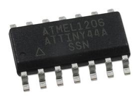
A microcontroller looks basically like this: (this is actually the one we used for our assignment this week)
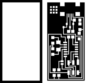
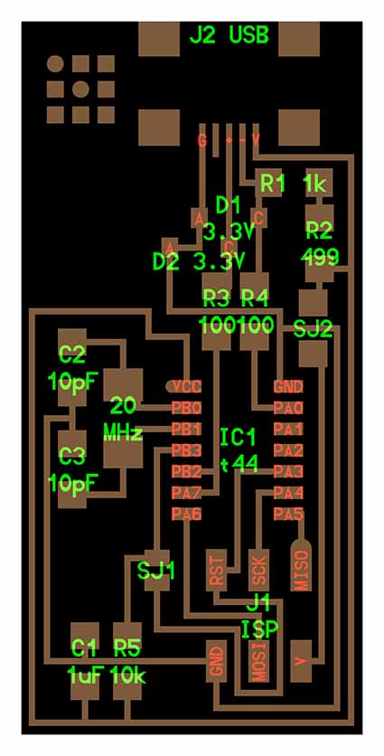
First thing we had to do is to choose the type of FabISP that we wanted to replicate. I chose Neil's one as seemed to me the most robust and tested solution among the others. This is the actual design of the board that we had to cut out to do our PCB (printed circuit board).
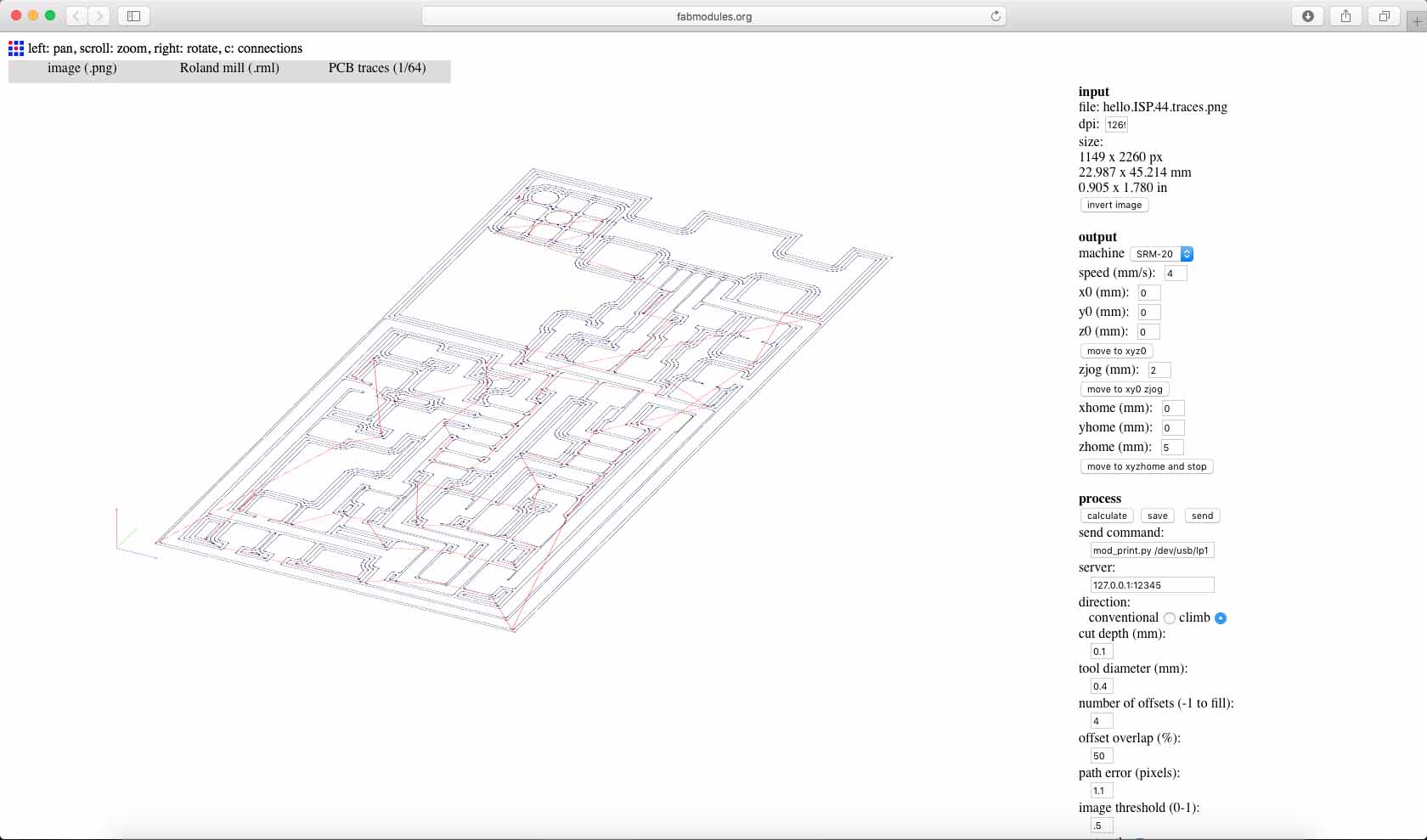
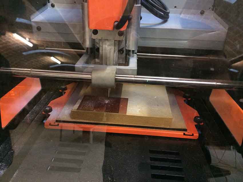
Through Fabmodules a .png file can be converted into a .rml, to mill our board as we want. The machine I have used is a Roland SRM-20. For the interior traces I have used a 1/64 end mill, and for the outline a 1/32. Once we have chosen all these options we can download the file and import it to the machine software.
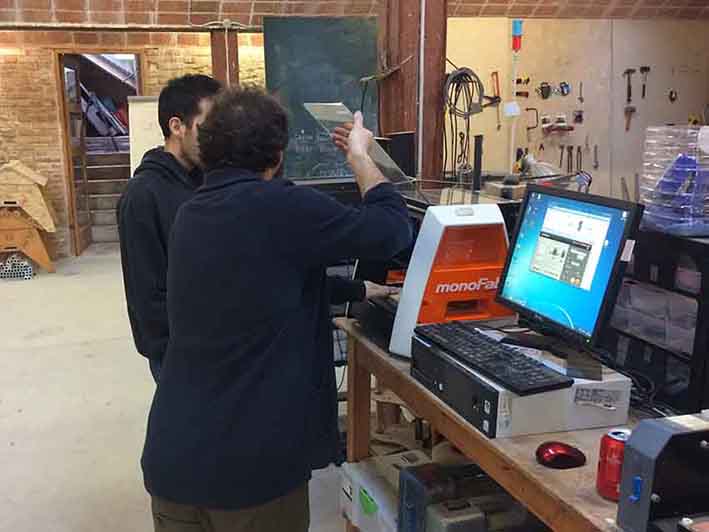
Santi showed us how to use the machine and how to cut the board.
First cleaning the surface of it and then puting double sided tape to make sure it won't move during the milling.
Milling consists basically on remove areas of copper from a PCB to recreate the pads and traces according to digital layout patterns.
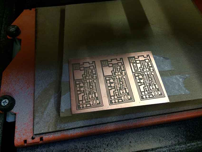
Here you see how we cut three boards at a time, first all the traces and then the exterior so that we just had to change the mill once.
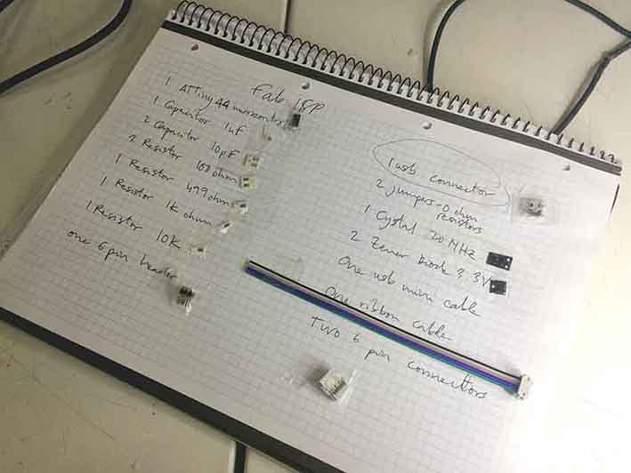
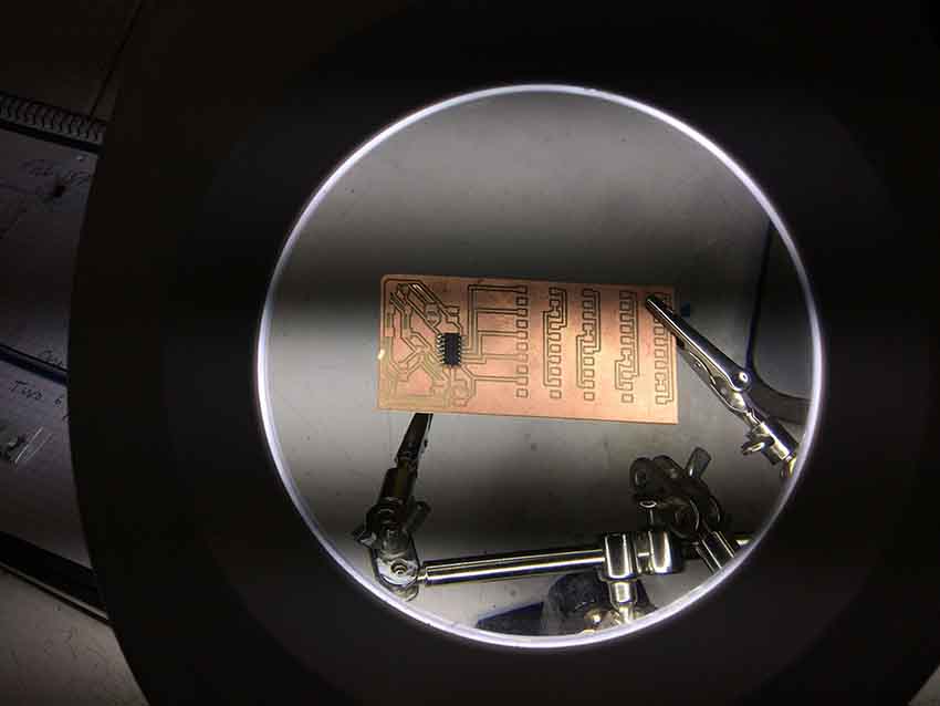
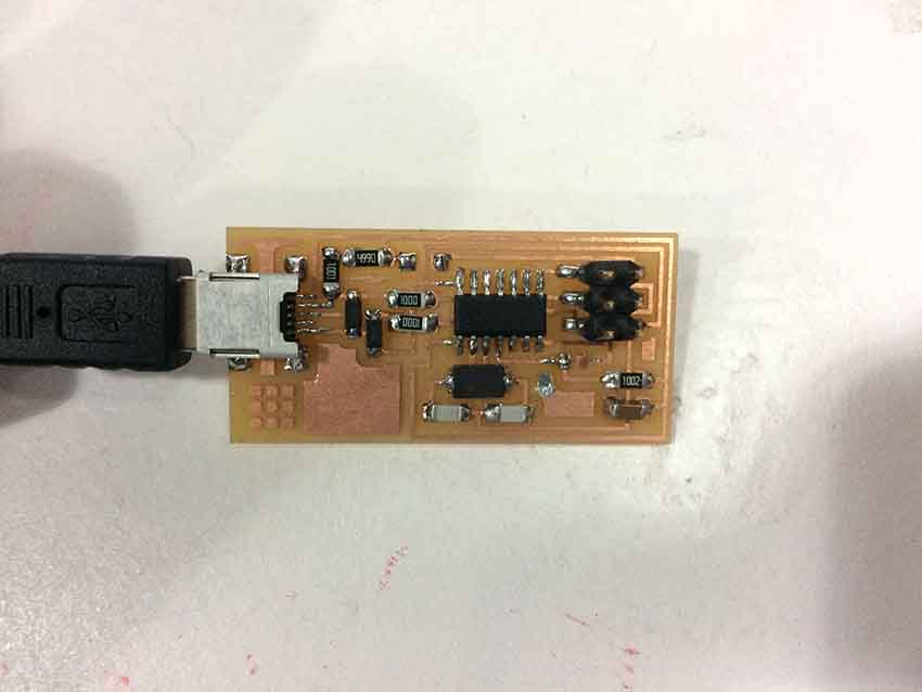
After that we polish our PCB and start looking for the components to integrate and solder on it. I made a list of all of them and stick them next to their name. I found this a very good system to structure and avoid losing any component.
I used Neil's components' diagram as a reference to solder all the components on their right place.
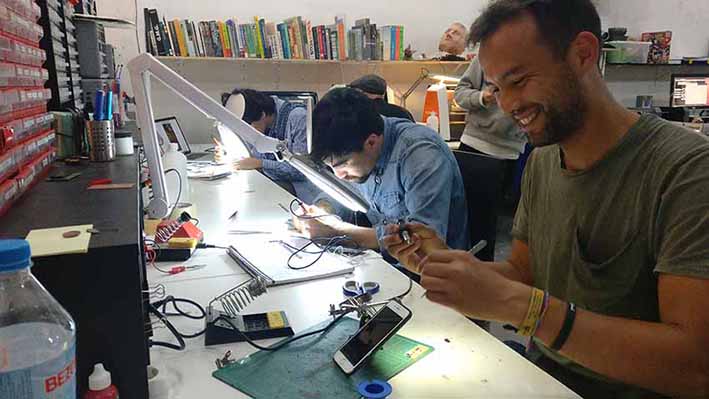
I started trying soldering first on an old PCB I found in the lab, with some microcrontoller which wasn't working either, just to start performing on the soldering process. I have to say I found it quite hard at the beginning, as most of the components where really small.
A picture that captured a moment of total attention while soldering. Seems that Jean Christophe was really enjoying it too! : )
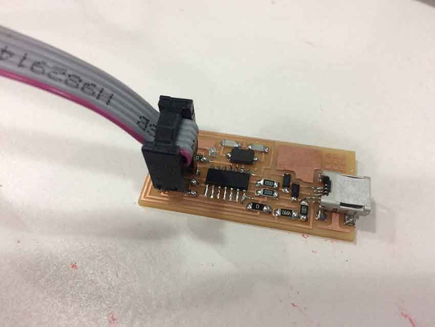
After soldering all the components and make sure connections were well done (I did that with a metrometer) it was ready to program. I plugged it into the computer and to another programmer at the same time. I used the ATAVRISP2 as it has lights that indicate if there's any problem while programming another board. First I checked the connectivity and was working fine.
I download the FabIsp firmware from here and followed the instructions there too. I used the terminal to make sure there was nothing inside my board with make clean command. Then I compiled all the files with make hex
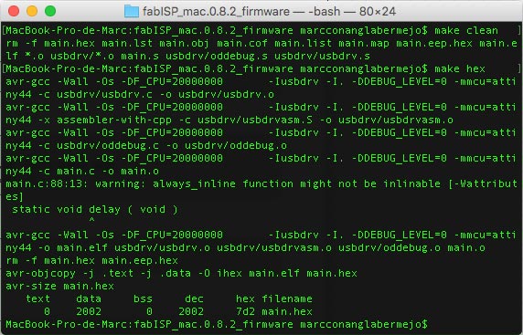
I set the fuses and the way the use the clock and make it work (among other things) with make fuse and then transfer everything to the microcontroller with make program

I took out the jumpers from the board, as they were only necessary for programming the FabIsp. Once done and to use it as a programmer for other boards they should be removed.
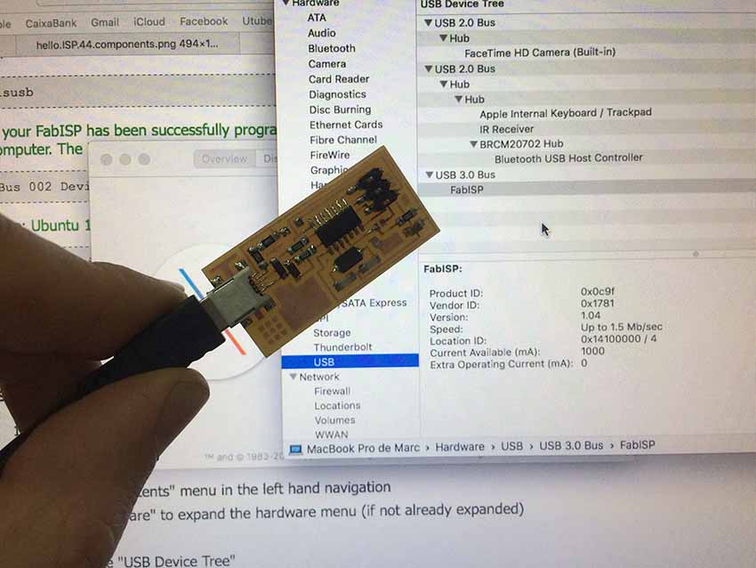
Lastly I checked the computer recognized the FabIsp, once connected to it.
I am very happy to have made my first programmer and I am looking forward to use it for programming some nice things on the coming weeks!
Download all the files here