Applications and implications
Week assignments:
· Propose a final project that integrates the range of units covered, answering:
What will it do? Who's done what beforehand? What materials and components will be required? Where will they come from? How much will it cost? What parts and systems will be made? What processes will be used? What tasks need to be completed? What questions need to be answered? What is the schedule? How will it be evaluated?
· Projects can be separate or joint, but need to show individual mastery of the range of skills covered.
Where possible, you should make rather than buy the parts of your project
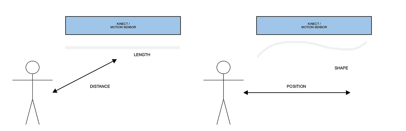
My final project will consist on an interactive kinetic installation, which will change its shape depending on people's around movement.
This a basic schematic about the idea, and how I have imagined inputs & outputs to work on it. Basically distance will determine how the objects move up and down. The further you are the lower the objects will be, so you see them and they catch your attention. As you move along and you change your position, the objects will move themselves accordingly, creating a "wave" that follows your movement.
First thing that comes to our mind when we talk about kinetic (at least for me) is BMW museum, where they explain car's history through an interesting and really well executed installation. See below:
Similar installations have been done, but they are all based in quite the same concept, with more or less amount of movement objects.
None of the above use any input, apart from the programmed movement. Below a cool project which is based on people's position to determine to lenght of some tubes, creating amazing shapes.
As you can imagine all these projects use really high precision engines + rotatory encoders to track the exact position of the motor every time. I was investigating for a while which kind of motors were involved on these kind of installations, and contacted with Beckhoff (engine manufacturarer) to know more about them.
I asked precisely about the AM3121 model, which seems to be running the BMW sculpture. Here you have its datasheet:
I honestly expected them to be expensive but not that much. Every single motor costs around 1000€, but it needs also a encoder + driver wire, which makes it even more expensive (around 1500€ for each module). So the whole installation cost can be roughly calculated by multpliying the number of motors by its cost (thousands of euros).
I find this one of the most challenging parts of the project, being able to do a "fab" version whithout wasting a lot of money, but at the same time doing something which is still precise and beautiful.
At the same time and due to its high cost, there's not too much open information on the net, as most of the projects have been done for commercial purposes.
I started trying some hooby servos and dc motors, but none of them seem to work well as they weren't precise enough. A part from that, there were a lot of limitations such the amount of motors that can be connected at the same time and its reliability with intense use. After more research I found some work from Özgür Atmaca, who more or less intented to do the same I want, and advice me on the type of motors I should be using. Below a video with part of the research he did:
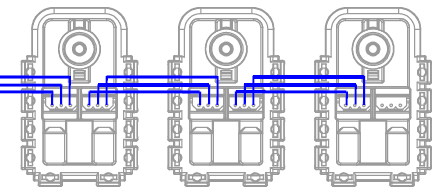
I finally decided to use Dynamixel AX-12A which is a motor mainly used for robotics. Apart from being a very robust engine, its main features are the possibility to send and receive data at the same time, thanks to the internal microcontroller and sensors. Here you have the datasheet
Below a video which show some of its best characteristics, their speed of communication and their accuracy.
Besides this, it works with a daisy chain connection, which makes it very useful and handy.
There are apparently, a lot of boards to control this type of motors. Some of them more complex and some simpler, but more or less they do all the same. These are all the options I have found so far:
CM-530 / ArbotiX-M / USB2Dynamixel / OpenCM9.04-C
I bought OpenCM9.04-C as it was the cheapest one and apparently all the hardware is OpenSource. Here there's more information about the board itself.
I used SMPS2Dynamixel Adapter to power the board from a 12V external power supply and receiving/sending data from the board to the motors.
Besides the hardware controllers there are different software options to program and control the Dynamixel, but OpenCM IDE seems to be the most logical one to use. You can download it here
After some more research I heard about USB2AX which is a small device developed by Xevelabs, to control the Dyamixel AX series. This will be indeed, the board reference for my project as I will do a Fab version of it. USB2AX was designed to be a really small device for robotic projects, so it could be very portable, connected to a small computer and the robot itself. Due to that it uses really tiny components. In my case, space is not a very big issue, so I have decided to change most components for Fab ones, even if they are a bit bigger. I have too, deleted some security components as they were special parts that need to be asked in purpose.
This is the Eagle schematic of the board, which will connect the computer with the first motor of the chain. The motor at the same time will be connected to the power supply board, and the rest of the motors.
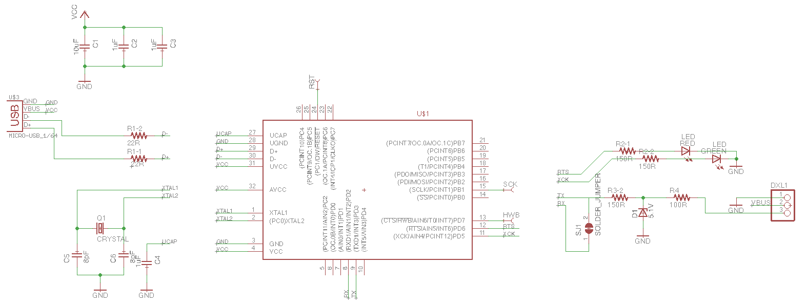
This is the list of components (BOM) needed to build the board:
U1 1 ATMega32u2 MCU / Alternatively ATMega16u2
Q1 1 SMD 16MHz quartz 16MHz CRYSTAL-SMD-3.2×2.5
USB1 1 USB Micro type
DXL1 1 Dynamixel Connector (pin header)
C1 1 USB decoupling capacitor 10µF
C2,C3 2 ATmega decoupling capacitors 1.0µF
C4 1 Capacitor for UCAP 1.0µF
C5,C6 2 Load capacitor for quartz 8pF
R1 2 USB line resistor 22R
R3 2 DATA line protection and current limiting resistor array for LEDs 150R
RPTC1 1 PTC resistor for DATA overvoltage protection 100R
D1 1 Zener diode for DATA overvoltage protection 5.1V SOD-923
LED1 1 Double LED Green/Red
1 Heat-shrink tubing (diam:12,7mm)(length:24mm+/-1mm)(TRANSPARENT)
Besides the board of materials, there are other things necessary to build the prototype:
10 Dynamixel AX-12A motors
1 SMPS2Dynamixel Adapter
1 12V 1A power supply
1 Microsoft Kinect V1
2 OSB boards (1250*2500mm)
10 plastic balls (160gr. each)
And finally a computer will be needed to read and send the data in real-time, connected to the main board.
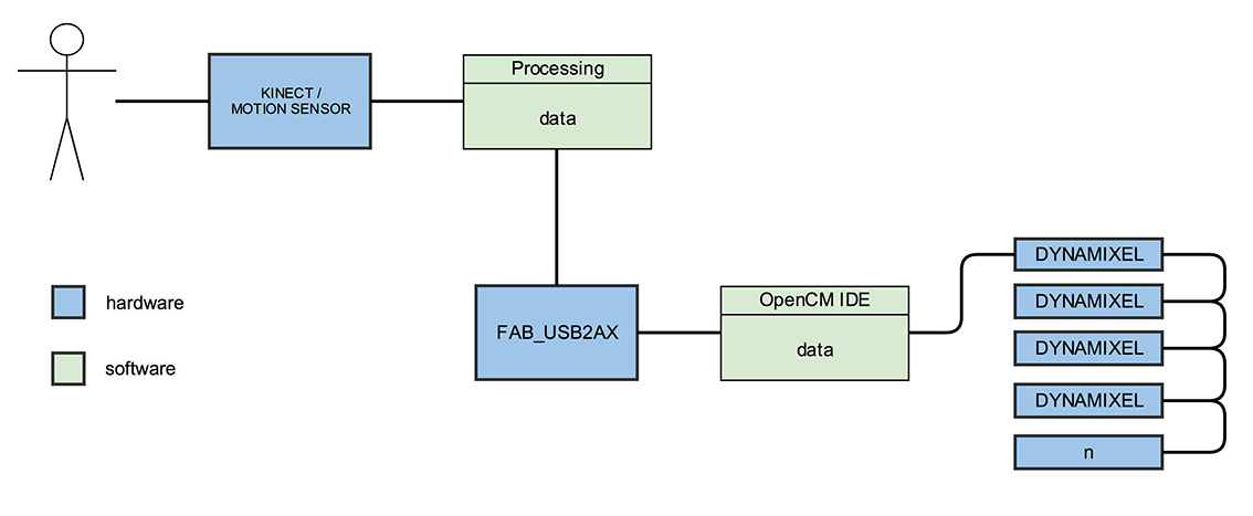
Here's the schematic that shows the general workflow.
I have already done some tests with the AX-12A motor, to try its general behaviour, and to see how heavy the objects can be to moved up and down. In week 8 and in the final project page I have some videos that show some trials in Arduino and OpenCM IDE to code the motors.
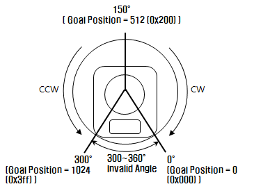
AX-12A has two different modes: continous and rotational. First one seems to be at first sight the best one for the project, but in this mode is impossible to control the motor really detailed. So the idea is to make it work in rotational mode, where it can rotate from 0º to 300º from 0 to 1024.
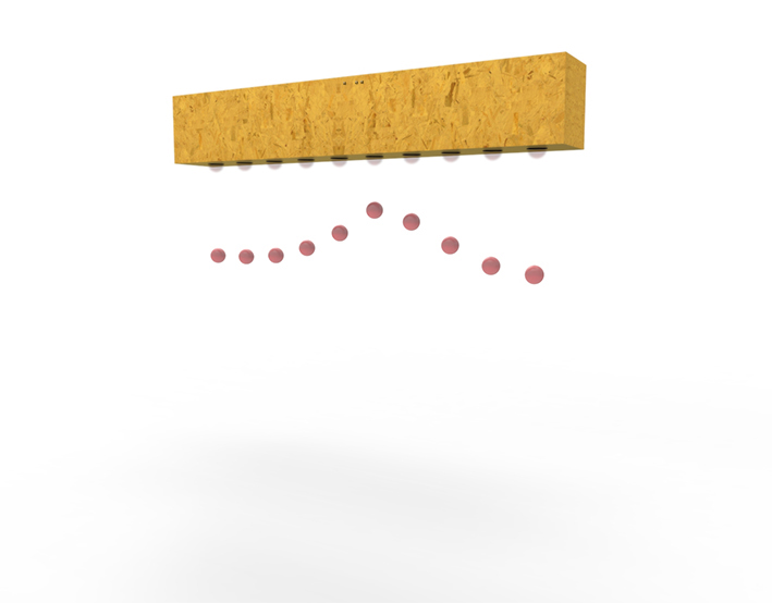
These are some renders that show how it will look, I still have to think how to fix it to the wall or how to make it stand on the floor.
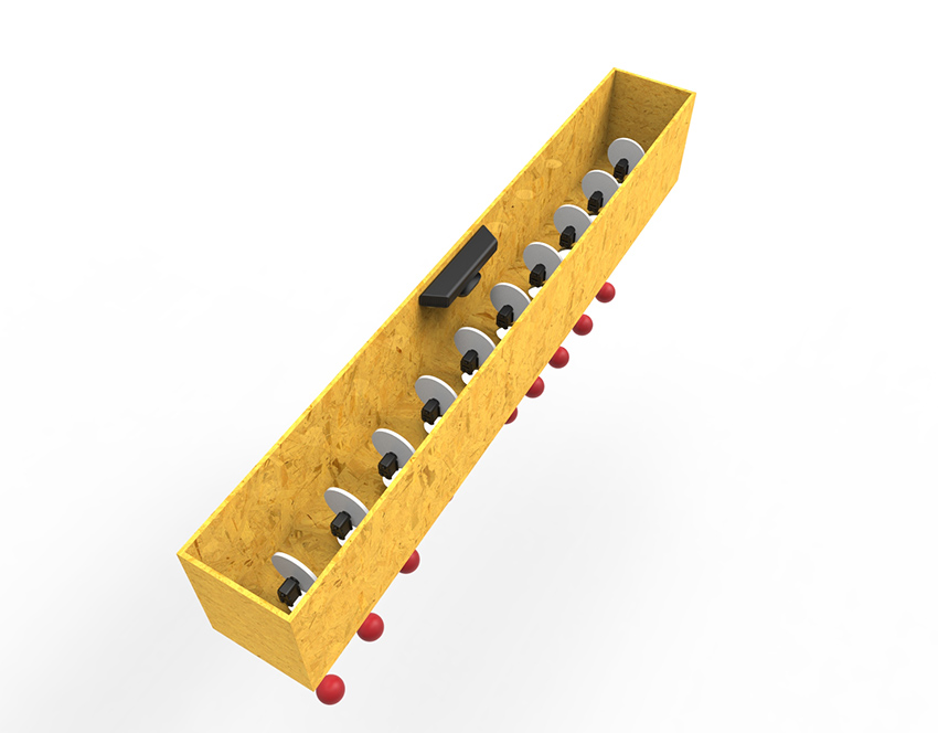
An inside look show all the components that might be included in the prototype, and the way they will be mounted inside the wood structure.
For the scheduling in the weeks to come:
Week 29th of May > Fab-USB2AX design / Wood Structure and first trials, without interaction
Week 5th of June > Programming and interaction
Week 12th of June > Finetuning